ELTEX EXR5C Series User manual

Operating Instructions
Series EXR5C Discharging Bars
for AC Operation
BA-en-2019-2006
F00009y

2BA-en-2019-2006_EXR5C

BA-en-2019-2006_EXR5C 3
List of contents
1 Outline of appliance EXR5C . . . . . . . . . . . . . . . . . . . . . . . . . . . . . 6
2 Safety. . . . . . . . . . . . . . . . . . . . . . . . . . . . . . . . . . . . . . . . . . . . . . . . 7
2.1 Proper use . . . . . . . . . . . . . . . . . . . . . . . . . . . . . . . . . . . . . . . . . . . . 7
2.2 Identification of risks and hazards . . . . . . . . . . . . . . . . . . . . . . . . . . 8
2.3 Work and operational safety. . . . . . . . . . . . . . . . . . . . . . . . . . . . . . . 8
2.4 Contact protection . . . . . . . . . . . . . . . . . . . . . . . . . . . . . . . . . . . . . . 9
2.5 Inspection of the protective resistors - contact protection . . . . . . . . 9
2.6 Technical advance . . . . . . . . . . . . . . . . . . . . . . . . . . . . . . . . . . . . . 10
3 Installation and assembly . . . . . . . . . . . . . . . . . . . . . . . . . . . . . . 11
3.1 Assembling the discharging bar . . . . . . . . . . . . . . . . . . . . . . . . . . . 11
3.2 Length of the high voltage cable. . . . . . . . . . . . . . . . . . . . . . . . . . . 15
3.3 Adjust the angle coupling . . . . . . . . . . . . . . . . . . . . . . . . . . . . . . . . 15
4 Operation. . . . . . . . . . . . . . . . . . . . . . . . . . . . . . . . . . . . . . . . . . . . 16
4.1 Startup . . . . . . . . . . . . . . . . . . . . . . . . . . . . . . . . . . . . . . . . . . . . . . 16
4.2 Function control . . . . . . . . . . . . . . . . . . . . . . . . . . . . . . . . . . . . . . . 16
5 Maintenance . . . . . . . . . . . . . . . . . . . . . . . . . . . . . . . . . . . . . . . . . 17
6 Trouble-shooting . . . . . . . . . . . . . . . . . . . . . . . . . . . . . . . . . . . . . 18
7 Warranty . . . . . . . . . . . . . . . . . . . . . . . . . . . . . . . . . . . . . . . . . . . . 19
8 Technical specifications EXR5C . . . . . . . . . . . . . . . . . . . . . . . . . 20
9 Dimensions . . . . . . . . . . . . . . . . . . . . . . . . . . . . . . . . . . . . . . . . . . 21
10 Spare parts and accessories. . . . . . . . . . . . . . . . . . . . . . . . . . . . 22
Declaration of Conformity . . . . . . . . . . . . . . . . . . . . . . . . . . . . . . . . . . 23

4BA-en-2019-2006_EXR5C
Dear customer
The EXR5C discharging bars are designed for the active discharging of
disruptive static charges which develop in production processes in explo-
sion hazard area.
The discharging bars and the power supply are used mainly in cases
where disruptive static charges on fast-moving material webs impair pro-
duction processes and need to be eliminated. The bars are operated with
an alternating voltage of 5 kV at 50…60 Hz and are approved for use in
explosive atmosphere of the group IIG and IID and comply with the device
category 2 (Category 2 apparatus, zone 1).
The advantages of the EXR5C discharging bar:
• ultimate discharge range and hence enhanced depth effect
• high active discharge power through patented, isolated ground
conductors
• high safety standards through passive discharge power with deacti-
vated power supplies
• safety through function and malfunction monitoring
• continuous assembly slotting guarantees flexible installation
• no health hazards in case of electric shocks when making contact with
individual tips (≤10 tips).
Due to differences in the surface charge profiles on different materials,
charges with both polarities are provided by the discharging bars. The
corona section with its optimized geometrical configuration ensures ulti-
mate discharging efficiency.
The optimum discharge effect is guaranteed in conjunction with the
ES53/G.. resp. ES53/H.. resp. ES53/I.. Eltex high voltage power supplies.
Please read the operating instructions carefully before starting the instru-
ment. This will help you prevent personal injuries and damage to property.
Please give us a call if you have any suggestions, proposals or ideas for
improvements. We greatly appreciate feedback from the users of our
appliances.

BA-en-2019-2006_EXR5C 5
1. Outline of appliance EXR5C
Maximum active length = 5910 mm
Grid width = 15 mm
EL = Installation length
AL = Active length
GL = Total length
The high voltage cable leads out from the bar in either an axial or radial
direction and is firmly encapsulated with the bar. The radial connection
can be rotated by 360° and is locked in the desired position by means of a
lock nut.
Fig. 1:
Overview and
dimensions of the
EXR5C
discharging bar
Z00077y
40
X
16
R60
AL
EL
95 GL
35 35
34
31,5
X
19
Ø17
Ø10
ca. 50
30
0...360°
(max. 1 turn)

6BA-en-2019-2006_EXR5C
2. Safety
The Series EXR5C discharging bars have been designed, built and tested
using state-of-the-art engineering and have left the factory in a technically
and operationally safe condition. If used improperly, the bars may never-
theless be hazardous to personnel and may cause injury or damage.
Read the operating instructions carefully and observe the safety notices.
Always observe the rules and regulations applying in your country with
reference to opening and repairing electrical appliances in explosion
hazard area.
Warning!
Do not touch the emission tips of the discharging bars when the supply
voltage from the power supply is switched on. Always disconnect the sup-
ply voltage to the power supply before carrying out any cleaning or main-
tenance work.
The manufacturers will not assume any liability and warranty if the units
are used improperly or outside the intended purpose.
2.1 Proper use
The Series EXR5C discharging bars must be used only for discharging
static charges from material surfaces. Other uses are not permitted.
The EXR5C discharging bars must be operated only together with the
dedicated ES53/G.. resp. ES53/H.. resp. ES53/I.. Eltex power supplies.
These power supplies guarantee the optimum adaptation to the required
operational data for the different active bar lengths. Safe operation of the
bars is ensured only by using the Eltex power supplies.
Modifications or changes to the discharging bars are not permitted.
Use only original Eltex spare parts and equipment.
2.2 Identification of risks and hazards
Possible risks and hazards resulting from the use of the units are referred
to in these operating instructions with the following symbols:
Warning!
This symbol appearing in the operating instructions refers to operations
which, if carried out improperly, may result in serious personal injury.
Caution!
This symbol appearing in the operating instructions refers to operations
which, if carried out improperly, may result in damage to property.
Ex Warning!
This symbol denotes the special conditions which must be observed when
operating the system in explosion hazard areas as specified in the EX
approvals.
Ex!

BA-en-2019-2006_EXR5C 7
2.3 Work and operational safety
Warning!
Carefully observe the following notes and the complete chapter 2 "Safety”,
page 6!
• Before carrying out repairs, cleaning or maintenance work and before
resetting the unit after malfunctions, switch off the power supply and dis-
connect the supply voltage (see chapter 5 "Maintenance”, page 17,
chapter 6 "Trouble-shooting”, page 18).
• Before carrying out any work involving the units, the machine which has
the units fitted must not be in operation (see chapter 5 "Maintenance”,
page 17, chapter 6 "Trouble-shooting”, page 18).
• Any work involving the units must be carried out by qualified electricians
(see chapter 5 "Maintenance”, page 17, chapter 6 "Trouble-shooting”,
page 18).
• The unit may only be used by qualified personnel trained for explosion
hazard areas.
• The bars passively absorb energy from the moving substrate web. The
high voltage cable must be plugged in or grounded to the power supply.
If the high voltage cable is disconnected, the plug is live (high voltage)
and applies with full power on the plug; this may cause a spark discharge
and may lead to a risk of injury. Disconnected high voltage plugs are not
permitted or have to be grounded (see chapter 5 "Maintenance”,
page 17).
• The bar must be mounted such that mechanical damage to the bar tips is
ruled out (see chapter 3.1 "Assembling the discharging bar”, page 10).
• To attach the bars, use only sliding nuts and bolts made of plastic (see
chapter 3.1 "Assembling the discharging bar”, page 10).
• In explosion dust hazard areas provide that the tips of the bar point either
horizontally or vertically downwards or at any angle between these two
positions and that the flash power of the dust is >0.4 mJ (see chapter 3.1
"Assembling the discharging bar”, page 10, chapter 8 "Technical specifi-
cations EXR5C”, page 20).
• When routing the cable, select the attachment points such that mechani-
cal damage to the cable (e.g. chafing against rotating machine parts) is
ruled out (see chapter 3.1 "Assembling the discharging bar”, page 10).
• In applications involving moving bars (e.g. film draw strips), the high volt-
age cable must be attached such that there is no cable movement near
the connection zone of the power supply unit (see chapter 3.1 "Assem-
bling the discharging bar”, page 10).
• If electrically conductive substrates or substrates coated with conductive
material (e.g. metal foil or metal composites) are used in the printing
process, the discharging and the mains voltage of the generator must be
switched off in these printing units.
Ex!

8BA-en-2019-2006_EXR5C
• In bilateral discharging, the bars must not be mounted in opposition to
each other. The distance between both bars should be greater than
twice the bar distance from the web (see chapter 3.1 "Assembling the
discharging bar”, page 10).
• Both the lengths of the high voltage cable and of the active bars are
limited, observe maximum lengths (see chapter 3.2 "Length of the high
voltage cable”, page 14).
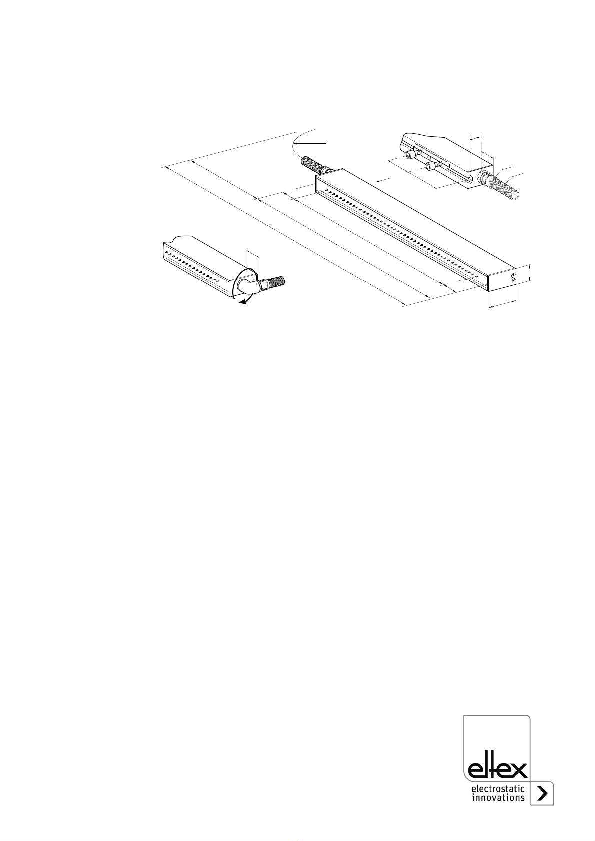
• The maximum permissible angle of turn of the angle coupling is 360°
(see chapter 3.3 "Adjust the angle coupling”, page 14).
• Before connecting the high voltage cables to the power supplies / dis-
tributors, the machine which has the bars fitted must not be in operation
and the supply voltage to the power supply must be disconnected (see
chapter 3.4 "Connecting the high voltage cable to the power supplies
and the distributor boxes”, page 15, chapter 5 "Maintenance”, page 17,
chapter 6 "Trouble-shooting”, page 18).
• Check the discharging bars and the high voltage cables at regular inter-
vals for any damage. Damaged components must be repaired or
replaced before continuing to operate the unit, or the bar or cable must
be disabled.
• The function control of the discharging bars has to be done outside of
the explosion hazard area (see chapter 4.2 "Function control”,
page 16).
• Keep the bars clean at all times.
Dirt results in malfunctions and in premature wear of the units.
• When cleaning the bars do not soak the bars and the high voltage cable
in solvent and do not damage the emission tips; allow the solvent to
evaporate completely before restarting the unit (see chapter 5 "Mainte-
nance”, page 17), chapter 6 "Trouble-shooting”, page 18).
• In explosion hazard areas Group II Gas subdivision B it must be
ensured that the possibility of the discharge pins being effectively con-
nected together, e.g. by dirt or contamination, is avoided.
• Do not touch the emission tips - risk of injury.
If the high voltage supply is connected, reflex responses to electrical
irritation can lead to secondary accidents; the charging bar as such is
safe to touch. If contact is made (≤10 tips), the energy transferred is so
low that there is no risk of injury.
• Potential risk for wearers of cardiac pacemakers:
Moving the chest closer than 3.5 cm to the emission tips of the dis-
charging bars or making surface contact with several emission tips
(touching a single tip is not critical) can result in a temporary switchover
of the cardiac pacemaker into the fault mode. Permanent proximity or
contact can therefore cause severe problems. If it is likely that the chest
of such a person comes closer than 3.5 cm to the emission tips of the
Ex!

BA-en-2019-2006_EXR5C 9
discharging bar, or if several emission tips are touched at the same time,
the appropriate warning notices must be displayed.
• Mechanical or electrical modifications of the discharging bars are not
permitted. Shortening the shielded high voltage cable on the connecting
side of the power supply is permitted. Extending the cable is permitted
only when using the Eltex distributor as well as original high voltage
cables and glands.
• The operation of the bars can generate ozone. The ozone concentration
levels developing near the bars depend on many different factors such
as site of installation, bar current and voltage, air circulation, etc., and
can therefore not be specified in general terms.
If the maximum allowable concentration of ozone must be observed at
the site of installation of the bar, the concentration must be measured on
site.
The AGW value (maximum admissible concentration) serves to assess
the ozone concentration at the workplace. The user must make sure that
the appropriate national AGW value is at no times exceeded, e.g. in
Germany the ozone concentration occurring during the operation of the
system must not exceed the recommended value based on international
limits of 0.06 ml/m³ (0.12 mg/m³).
2.4 Contact protection
As the site of installation and/or use of the units is outside the control of
Eltex, contact protection against inadvertent contact by personnel as spec-
ified by the employers’ liability insurance association have to be provided
(e.g. DGUV V3 in Germany). Contact protection made of conductive mate-
rial must be grounded.
2.5 Inspection of the protective resistors - contact protection
The function and the appearance of the protective resistors must be
inspected at regular intervals. The inspection intervals are specified in the
accident prevention regulations, as amended (e.g. in Germany DGUV V3).
The function of the series resistors must be checked using a suitable
measuring device. The test voltage must be 1,000V. The measured resis-
tance between the high-voltage connection and the individual emission tip
must not fall below 120 MOhm and not exceed 180 MOhm.
2.6 Technical advance
The manufacturer reserves the right to make changes to the technical
specifications without prior notice in order to adapt the units to state-of-the-
art engineering. Eltex will provide the latest information on any changes or
modifications in the operating instructions on request.

10 BA-en-2019-2006_EXR5C
3. Installation and assembly
3.1 Assembling the discharging bar
Attach the Series EXR5C discharging bars to the machine wall, using
flame-retardant GRP assembly material. For easier installation we recom-
mend using the assembly material offered by Eltex. Fig. 2 shows the
installation principle.
The profiled assembly section of the discharging bar is grooved. The slid-
ing nuts pushed into this groove serve as bolt attachments for the GRP
material, allowing the discharging bars to be installed.
Max. bolt depth 6.5 mm
Torque 0.4 Nm
Secure bolts (e.g. Loctite 243)
Caution!
Use only sliding nuts and bolts made of plastic!
below 1 meter total length: 2 per bar
below 2 meters total length: 3 per bar
below 3 meters total length: 4 per bar
below 4 meters total length: 5 per bar
below 5 meters total length: 6 per bar
below 6 meters total length: 7 per bar
An optional alternative is attaching the bars using a round GRP rod. Fig. 4
shows an assembly example. The bar is attached to the GRP rod via plas-
tic holders plugged into the installation groove. Longer bars require an
additional angle bracket bolted to the GRP rod to prevent the bar from
sagging.
Fig. 2:
Assembling the
discharging bar
Z00335y
7
7
15 15 5
40 M5 (3x)
~50 30

BA-en-2019-2006_EXR5C 11
Plastic holder
below 1 meter total length: 3 per bar
below 2 meters total length: 5 per bar
below 3 meters total length: 7 per bar
below 4 meters total length: 9 per bar
below 5 meters total length: 11 per bar
below 6 meters total length: 13 per bar
1bar
2GRProd
3 plastic holder
4 machine wall
5 high voltage cable with flexible tube
Fig. 3:
Assembly example
EXR5C with GRP
rod and steel
brackets for
attachment to the
machine wall
Z00121y
2
1
4
5
Fig. 4:
Assembly example
EXR5C with GRP
rod
Z00334y
4
3
2
1
3
5
>200

12 BA-en-2019-2006_EXR5C
Warning !
For safety in operation, please note the following:
• The bar must be mounted such that mechanical damage to the bar tips
is ruled out.
• To attach the bars, use only sliding nuts and bolts made of plastic.
• In explosion dust hazard areas provide that the tips of the bar point
either horizontally or vertically downwards or at any angle between
these two positions and that the flash power of the dust is >0.4 mJ.
• When routing the cable, select the attachment points such that
mechanical damage to the cable (e.g. chafing against rotating machine
parts) is ruled out.
• In applications involving moving bars (e.g. film draw strips), the high
voltage cable must be attached such that there is no cable movement
near the connection zone of the power supply unit.
• Switch off the bar when working with metal film or metal composites!
Ex!

BA-en-2019-2006_EXR5C 13
Locating the discharging bar
The best possible discharge results are achieved if the bar is located in
areas with minimum web capacities. In practical terms this means placing
the bar with maximum distances from the machine environment, i.e. no
installation of the discharging bar at idler rollers.
A rough guideline:
A space with the radius R of the bar distance from the web ought to be
kept free of any conductive material (Fig. 5). The distance of the emission
points to the conductive, earthed printing press area should be greater
than to the substrate to be discharged.
Depending on application, the distance between discharging bar and sub-
strate ought to be 30...100 mm.
In bilateral discharging, the bars must not be mounted in opposition to
each other. The distance between both bars should be greater than twice
the bar distance from the web.
Fig. 5:
Zone free of con-
ductive material
with the dimen-
sions R
Z00076y
R
>2R
R
R

14 BA-en-2019-2006_EXR5C
3.2 Length of the high voltage cable
Both the lengths of the high voltage cable and the active bars are limited.
The shielded high voltage cables cause a capacitive load on the trans-
former inside the power supply. The maximum loading capacity is a result
of the function of the total active bar length and the total length of all high
voltage cables. Fig. 6 demonstrates this principle for the supplies ES53.
Example: The maximum permissible total cable length with a 3 meter
active bar length is 32 meters.
Connecting the ES53/G.. resp. ES53/H.. resp. ES53/I.. power supply see
Operating Instructions of the power supply.
3.3 Adjust the angle coupling
If the bar has a angle coupling, then it is aligned towards the tips during ex
factory delivery.
To turn the angle connection, proceed as follows:
• loosen the lock nut
• align the angle coupling in its desired position
• re-tighten the lock nut
The maximum permissible angle of turn of the angle coupling is 360°.
Fig. 6:
Loading capacity
of the power
supplies ES53 as
factor of bar length
and length of high
voltage cable
Z00041e
Σlengths of h.v. cable [m]
Σlengths of active bars [m]
15
10
5
10 20 30 40 50
permissible
range
Fig. 7:
Angle coupling
1 lock nut
2 angle coupling
Z00065y
1
2
0...360°
(max. 1 turn)

BA-en-2019-2006_EXR5C 15
3.4 Connecting the high voltage cable to the power supplies and
the distributor boxes
The connection of the high voltage cable of the discharging bars to the
power supplies is described in the operating instructions of the respective
power supplies.
Warning!
Electric shock hazard!
Work may be carried out only if:
• the supply voltage to the power supply has been disconnected,
• the machine is at standstill because the bars pick up charges
if the substrat web is running.

16 BA-en-2019-2006_EXR5C
4. Operation
The discharging bars must be operated only in connection with the ES53/
G.. resp. ES53/H.. resp. ES53/I.. Eltex power supplies with 5 kV AC output.
These power supplies guarantee the optimum adaptation to the specified
operating conditions and are approved for use in explosive atmosphere.
4.1 Startup
Once all the connections and the installation have been correctly made, the
system is operational and the supply voltage can be switched on at the
power supply.
4.2 Function control
Use the Eltex Volt Stick or a glow-lamp voltage tester to check the proper
function of the emission tips. Quote Article No. 109136 when ordering the
Volt Stick from Eltex.
Ex-Warning!
The function control has to be done outside of the explosion hazard area.
Ex!

BA-en-2019-2006_EXR5C 17
5. Maintenance
Warning!
Electric shock hazard!
• Do not carry out any maintenance or repair work without first switching
off the power supply and disconnecting the supply voltage.
• The bars passively absorb energy from the moving substrate web. The
high voltage cable must be plugged in or grounded to the power supply.
If the high voltage cable is disconnected, the plug is live (high voltage)
and applies with full power on the plug; this may cause a spark dis-
charge and may lead to a risk of injury. Disconnected high voltage plugs
are not permitted or have to be grounded.
• The machine which has the units fitted must not be in operation.
• Repairs and maintenance work must be carried out by qualified electri-
cians only.
To ensure the trouble-free function of the discharging bars, clean the bars
at least once a week with compressed air free of oil and water (6 bar and
standard compressed air pistol) and a brush with soft plastic bristles.
In explosion hazard areas Group II Gas subdivision B it must be ensured
that the possibility of the discharge pins being effectively connected
together, e.g. by dirt or contamination, is avoided.
Clean grease, ink, glue, paper dust, etc. off the discharging bar using a
suitable solvent (Cleaning gasoline). Do not soak the bars and the high
voltage cable in solvent!
Warning!
Risk of deflagration!
Allow the solvent to evaporate before restarting the unit.
Caution!
Do not damage the emission tips when cleaning. Brush only in longitudinal
direction.
Inspection of the protective resistors - contact protection
The function and the appearance of the protective resistors must be
inspected at regular intervals. The inspection intervals are specified in the
accident prevention regulations, as amended (e.g. in Germany DGUV V3).
The function of the series resistors must be checked using a suitable
measuring device. The test voltage must be 1,000V. The measured resis-
tance between the high-voltage connection and the individual emission tip
must not fall below 120 MOhm and not exceed 180 MOhm.
Ex!

18 BA-en-2019-2006_EXR5C
6. Trouble-shooting
Warning!
Electric shock hazard!
• Do not carry out any maintenance or repair work without first switching
off the power supply and disconnecting the supply voltage. No voltage
must apply at the discharging bars.
• Repairs and maintenance work must be carried out by qualified electri-
cians only.
Malfunction:
Effectiveness of the application declining.
Cause:
Dirty discharging bars.
Measure:
Clean bar with compressed air and a brush. Clean grease, ink, oil, etc. off
the bar with a suitable solvent (Cleaning gasoline).
For further malfunctions, refer to the operating instructions for the power
supplies.
Caution!
Do not leave the discharging bar to soak in the solvent!
Warning!
Risk of deflagration!
Allow the solvent to evaporate before restarting the unit.

BA-en-2019-2006_EXR5C 19
7. Warranty
The units are warranted for a period of 12 months provided that the opera-
ting conditions have been maintained, that the units have not been tam-
pered with and that the units show no mechanical damage.
The warranty applies only if the operating and assembly instructions spe-
cified by Eltex have been observed. The warranty period begins on the
date of delivery.
In the event of defects occurring during the warranty period, the units or
defective components will be repaired at Eltex. Defective components will
be replaced and installed free of charge.
If repairs are required at the customer´s premises, the costs for sending a
technician (travel, travel time, expenses) will be charged to the customer.

20 BA-en-2019-2006_EXR5C
8. Technical specifications EXR5C
The current approvals with their supplements can be found at:
http://service.eltex.de.
Bar element glass-fibre-reinforced plastic GRP
Encapsulation material polyurethane, UL-94 V-0
Emission tips stainless steel
Installation material plastic sliding nuts
Operating
Ambient temperature 0...+40°C (+32...+104°F)
Ambient humidity max. 70 % RH, non-dewing
Dimensions profile: 16 x 40 mm, max. length 5,980 mm,
see Fig. 8
Weight approx. 0.8 kg/m
Operating voltage max. 5 kV AC, 50/60 Hz
High voltage supply via ES53/G.. resp. ES53/H.. resp. ES53/I.. Eltex
power supplies
High voltage
connection
high voltage cable encapsulated, axial or radial
(rotatable by 360°) lead-out
Short-circuit current/tip max. 0.046 mA
Contact protection according EN 61140
EX Approval BAS98ATEX2179X
II 2 G IIA T6 or
II 2 G IIB T6 if it is ensured that the possibility
of the discharge pins being effectively connected
together is avoided.
II 3 D T100 °C provided that the tips of the
bar point either horizontally or vertically down-
wards or at any angle between these two posi-
tions and that the flash power of the dust is
>0.4 mJ.
UL Approval
(EXR50US)
Class I, Group D; Class II, Group G; Class III;
File No. E81984
as shown on
aplliance
marking:
Table of contents
Popular Industrial Equipment manuals by other brands

Gamry Instruments
Gamry Instruments Faraday Shield Operator's manual

Stoll
Stoll CMS 933 operating instructions

APEX DYNAMICS
APEX DYNAMICS P Series user manual

GFA
GFA ELEKTROMAT KE 40.24-40,00 installation instructions

Siemens
Siemens Synco-Gamma Application guide

Dixon
Dixon 200-PV-9 Maintenance & Operating Intructions