manuals.online logo
Brands
  1. Home
  2. •
  3. Brands
  4. •
  5. Teledyne
  6. •
  7. Power Supply
  8. •
  9. Teledyne LeCroy T3PS Series User manual

Teledyne LeCroy T3PS Series User manual

www. .com information@itm.com1.800.561.8187
This chapter contains important safety
instructions that you must follow during
operation and storage. Read the following before
any operation to insure your safety and to keep
the instrument in the best possible condition.
These safety symbols may appear in this manual or on the
instrument.
Warning: Identifies conditions or practices that
could result in injury or loss of life.
Caution: Identifies conditions or practices that
could result in damage to the T3PS or to other
properties.
DANGER High Voltage
Attention Refer to the Manual
Protective Conductor Terminal
Earth (ground) Terminal
www. .com information@itm.com1.800.561.8187
Do not dispose electronic equipment as unsorted
municipal waste. Please use a separate collection
facility or contact the supplier from which this
instrument was purchased.
Do not place any heavy object on the T3PS.
Avoid severe impact or rough handling that
leads to damaging the T3PS.
Do not discharge static electricity to the T3PS.
Use only mating connectors, not bare wires, for
the terminals.
Do not block the cooling fan opening.
Do not disassemble the T3PS unless you are
qualified.
AC Input voltage range: 85Vac-265Vac
Input Power 2000 VA (Max)
Frequency: 47Hz to 63Hz
To avoid electrical shock connect the protective
grounding conductor of the AC power cord to
an earth ground.
www. .com information@itm.com1.800.561.8187
Use proper power cord.
Maintain ground. The AC inlet ground is
connected to the frame of the instrument. Connect
line cords only to outlets with safety ground
contacts.
Disconnect the power cord before cleaning.
Use a soft cloth dampened in a solution of mild
detergent and water. Do not spray any liquid.
Do not use chemicals containing harsh material
such as benzene, toluene, xylene, and acetone.
Location: Indoor, no direct sunlight, dust free,
almost non-conductive pollution (Note below)
Relative Humidity: 20%- 85% (no condensation)
Altitude: < 2000m
Temperature: 0°C to 50°C
www. .com information@itm.com1.800.561.8187
Location: Indoor
Temperature: -25°C to 70°C
Relative Humidity: 90%(no condensation)
Do not dispose this instrument as unsorted
municipal waste. Please use a separate collection
facility or contact the supplier from which this
instrument was purchased. Please make sure
discarded electrical waste is properly recycled to
reduce environmental impact.
www. .com information@itm.com1.800.561.8187
When using the power supply in the United Kingdom, make sure
the power cord meets the following safety instructions.
As the colours of the wires in main leads may not correspond with
the coloured marking identified in your plug/appliance, proceed
as follows:
The wire which is coloured Green & Yellow must be connected to
the Earth terminal marked with either the letter E, the earth symbol
or coloured Green/Green & Yellow.
The wire which is coloured Blue must be connected to the terminal
which is marked with the letter N or coloured Blue or Black.
The wire which is coloured Brown must be connected to the
terminal marked with the letter L or P or coloured Brown or Red.
If in doubt, consult the instructions provided with the equipment
or contact the supplier.
This cable/appliance should be protected by a suitably rated and
approved HBC mains fuse: refer to the rating information on the
equipment and/or user instructions for details. As a guide, a cable
of 0.75mm2should be protected by a 3A or 5A fuse. Larger
conductors would normally require 13A types, depending on the
connection method used.
Any exposed wiring from a cable, plug or connection that is
engaged in a live socket is extremely hazardous. If a cable or plug is
deemed hazardous, turn off the mains power and remove the cable,
any fuses and fuse assemblies. All hazardous wiring must be
immediately destroyed and replaced in accordance to the above
standard.
www. .com information@itm.com1.800.561.8187
This chapter describes the power supply,
including its main features and front / rear panel
introduction. After going through the overview,
please read the theory of operation to become
familiar with the operating modes, protection
modes and other safety considerations.
Series lineup ......................................................................................11
Main Features ...................................................................................11
Accessories ........................................................................................12
Front Panel........................................................................................13
Display and Operation Panel .........................................................16
Rear Panel..........................................................................................18
Operating Area Description...........................................................20
CC and CV Mode.............................................................................21
Slew Rate ...........................................................................................23
Bleeder Control ................................................................................23
Internal Resistance ...........................................................................24
Alarms ................................................................................................25
Considerations ..................................................................................26
Grounding .........................................................................................28
www. .com information@itm.com1.800.561.8187
The T3PS series consists of 3 models, covering a number of
different current, voltage and power capacities:
High power density: 1500W in 1U
Universal input voltage 85-265Vac, continuous
operation.
Output voltage up to 60V, current up to 200A.
Active power factor correction.
Parallel master/slave operation with active
current sharing.
Remote sensing to compensate for voltage drop
in load leads.
19" rack mounted ATE applications.
OVP, OCP and OHP protection.
Preset memory function.
Adjustable voltage and current slew rates.
Bleeder circuit ON/OFF setting.
www. .com information@itm.com1.800.561.8187
CV, CC priority start function. (Prevents
overshoot with output ON)
Built-in RS-232/485, LAN and USB interface.
Analog output programming and monitoring.
Before using the T3PS power supply unit, check the package
contents to make sure all the standard accessories are included.
www. .com information@itm.com1.800.561.8187
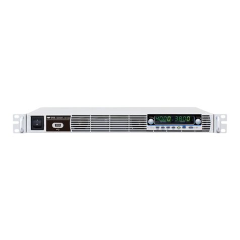
Lock/ Local PROT Function Test Set Output
Unlock ALM_CLR M 1 M2 M 3
Shift
: Long Push
VSR LAN RMT ERR DLY ALM ISR M1 M2 M3 RUN
C C
A
C V
V
VOLTAGE CURREN T
Voltage Current
2 3 4 5
Display Area
1
116 7 8 9 10 12 13
Used to turn the power on/off.
USB A port for data transfer,
loading test scripts etc.
Air inlet for cooling the inside of
the T3PS series.
Voltage
Used to set the voltage value or
select a parameter number in the
Function settings.
The display area shows setting values, output
values and parameter settings. The function LEDs
below show the current status and mode of the
power supply. See page 16 for details.
Current
Used to set the current value or
change the value of a Function
parameter.
www. .com information@itm.com1.800.561.8187
Lock/Loca
l
Unlock
Used to lock all front panel
buttons other than the Output
Button or it switches to local
mode.
(Long push) Used to unlock the
front panel buttons.
PROT
ALM_CLR
Used to set and display OVP, OCP
and UVL.
(Long push) Used to release
protection functions that have
been activated.
Function
M1
Used to configure the various
functions.
(+Shift) Used to recall the M1
setup.
(+Shift and hold) Used to save the
current setup to M1.
TEST
M2
Used to run custom
ized scripts for
testing.
(+Shift) Used to recall the M2
setup.
(+Shift and hold) Used to save the
current setup to M2.
SET
M3
Used to set and confirm the output
voltage and output current.
(+Shift) Used to recall the M3
setup.
(+Shift and hold) Used to save the
current setup to M3.
www. .com information@itm.com1.800.561.8187
Used to enable the functions that
are written in blue characters
below certain buttons.
Used to turn the output on or off.
Lights in green when the output is
on.
www. .com information@itm.com1.800.561.8187
VSR LAN RMT ERR DLY ALM ISR M 1 M 2 M 3 RUN
C C
A
C V
V
VOLTAGE CURRENT
Displays the voltage or the parameter number of a
Function parameter.
Displays the current or the value of a Function
parameter.
Lights in green during constant voltage mode.
Lights in green during constant current mode.
Lights up when CV Slew Rate Priority is enabled.
Lights up when the LAN interface is connected.
Lights in green during remote control.
Lights in red when an error has occurred.
The Output On/Off Delay indicator LED.
Lights in red when a protection function has been
activated.
www. .com information@itm.com1.800.561.8187
Lights up when CC Slew Rate Priority is enabled.
Lights in green when the memory value are being
recalled or saved.
Lights in green when the memory value are being
recalled or saved.
Lights in green when the memory value are being
recalled or saved.
others are green.
www. .com information@itm.com1.800.561.8187
S LS SLSNC
REMOTE SENSE
ANALOG PROGRAMMING RS485 / 232
OUT IN
LAN
DC OUTPUT
AC INPUT
L N
100 240V
2000VA MAX.
AC
47 63Hz
L N
AC INPUT
Wire clamp connector.
Output terminals for 6V to 60V
models.
USB port for controlling the T3PS
remotely.
LANRS 485 / 232
Ethernet port for controlling the
T3PS remotely.
LANRS 485 / 232
Two different types of cables can
be used for RS232 or RS485-based
remote control.
RS232 support via user supplied
cable with DB9 / RJ45 connectors
wired according to the table on
page 124.
www. .com information@itm.com1.800.561.8187
RS485 support via user supplied
cable with DB9 / RJ45 connectors
wired according to the table on
page 124.
RJ-45 connector that is used to
daisy chain power supplies with
the Remote-IN port to form a
communication bus.
Serial link cable with RJ45
shielded connectors wired
according to the table on page 129.
External analog control connector.
Compensation of load wire drop.
Connectors for grounding the output (two
positions, shown in red).
www. .com information@itm.com1.800.561.8187
T3PS062001P
T3PS40381P
T3PS60251P
www. .com information@itm.com1.800.561.8187

This manual suits for next models

6

Other Teledyne Power Supply manuals

Teledyne T3PS3000 User manual

Teledyne

Teledyne T3PS3000 User manual

Teledyne Power Pod 400 User manual

Teledyne

Teledyne Power Pod 400 User manual

Teledyne T3PS13206P User manual

Teledyne

Teledyne T3PS13206P User manual

Teledyne Battery-Backed Power Supply Operating instructions

Teledyne

Teledyne Battery-Backed Power Supply Operating instructions

Teledyne T3PS20051P User manual

Teledyne

Teledyne T3PS20051P User manual

Teledyne 3190 Series User manual

Teledyne

Teledyne 3190 Series User manual

Teledyne T3PS36006 User manual

Teledyne

Teledyne T3PS36006 User manual

Teledyne T3PS30721P User manual

Teledyne

Teledyne T3PS30721P User manual

Teledyne Power Pod 400 User manual

Teledyne

Teledyne Power Pod 400 User manual

Teledyne T3PSX3200P Series User manual

Teledyne

Teledyne T3PSX3200P Series User manual

Teledyne T3PS12415 User manual

Teledyne

Teledyne T3PS12415 User manual

Teledyne T3PS13206 User manual

Teledyne

Teledyne T3PS13206 User manual

Teledyne HASTINGS 200 Series User manual

Teledyne

Teledyne HASTINGS 200 Series User manual

Teledyne T3PS16081P User manual

Teledyne

Teledyne T3PS16081P User manual

Teledyne 913 Operating instructions

Teledyne

Teledyne 913 Operating instructions

Teledyne T3PS40381P Owner's manual

Teledyne

Teledyne T3PS40381P Owner's manual

Teledyne T3PS40381P User manual

Teledyne

Teledyne T3PS40381P User manual

Popular Power Supply manuals by other brands

IOGear GMP12K quick start guide

IOGear

IOGear GMP12K quick start guide

PR 2220 quick start guide

PR

PR 2220 quick start guide

HP D7171A - NetServer - LPr Upgrade guide

HP

HP D7171A - NetServer - LPr Upgrade guide

Dometic RAPS12R-U2 Installation and operating instructions

Dometic

Dometic RAPS12R-U2 Installation and operating instructions

Voltex CPP2HUSB installation guide

Voltex

Voltex CPP2HUSB installation guide

Bently Nevada 3300/10 manual

Bently Nevada

Bently Nevada 3300/10 manual

Njoy Garun Series user manual

Njoy

Njoy Garun Series user manual

Dynex DX-400WPS user guide

Dynex

Dynex DX-400WPS user guide

GE KTP-24C installation instructions

GE

GE KTP-24C installation instructions

EnerSys Alpha FMPS FTTP Installation & operation manual

EnerSys

EnerSys Alpha FMPS FTTP Installation & operation manual

Consort EV245 manual

Consort

Consort EV245 manual

Keysight MP4300 Series Operating and service guide

Keysight

Keysight MP4300 Series Operating and service guide

PCB Piezotronics 8120-110A Installation and operating manual

PCB Piezotronics

PCB Piezotronics 8120-110A Installation and operating manual

Longwei Electric LW1550KD quick start guide

Longwei Electric

Longwei Electric LW1550KD quick start guide

Allied Telesis AT-PWR9 installation guide

Allied Telesis

Allied Telesis AT-PWR9 installation guide

Allen-Bradley PowerFlex 700 AFE Migration guide

Allen-Bradley

Allen-Bradley PowerFlex 700 AFE Migration guide

Heathkit Heathkit HWA-7-1 Operation manual

Heathkit

Heathkit Heathkit HWA-7-1 Operation manual

Kramer MegaEdge user manual

Kramer

Kramer MegaEdge user manual

manuals.online logo
manuals.online logoBrands
  • About & Mission
  • Contact us
  • Privacy Policy
  • Terms and Conditions

Copyright 2025 Manuals.Online. All Rights Reserved.