© Copyright 2020 Eltra S.p.a. Unipersonale. Tutti i diritti di sfruttamento economico sono esclusivi e riservati.
Eltra si riserva di apportare senza preavviso eventuali modifiche alle specifiche descritte nelle presenti schede prodotto.
Per le note applicative e per le condizioni generali di vendita consultare il sito internet www.eltra.it.
ISTRUZIONI DI
INSTALLAZIONE
AAM 58 B / C / F PROFINET
CONNETTORI
Connettore PORT 1 / 2 (4 pin)
M12 chiave D
vista lato saldatura MV
Connettore POWER (4 pin)
M12 chiave A
vista lato saldatura FV
CONNESSIONI ELETTRICHE
Questo dispositivo deve essere alimentato da
un alimentatore di Classe 2 o con limitazione
della tensione / corrente
Tensione di ingresso: + 30V DC max
Corrente di ingresso: 0.5A max
Documentazione completa disponibile su www.eltra.it
PRECAUZIONI DI INSTALLAZIONE E DI UTILIZZO
• Il trasduttore deve essere utilizzato nel rispetto delle sue specifiche. Il trasduttore è uno strumento di
misurazione di precisione e non è un dispositivo di sicurezza.
• Il montaggio e la messa in servizio del dispositivo devono essere effettuate da personale qualificato e
seguire attentamente le istruzioni di installazione. Si consiglia vivamente di evitare qualsiasi modifica
meccanica o elettrica per motivi di sicurezza, la garanzia verrà meno in caso di eventuali modifiche.
• Non esporre il dispositivo a sollecitazioni o urti che potrebbero non garantirne il corretto funzionamento.
• Accertarsi che l’accoppiamento meccanico dell’albero del trasduttore sia progettato con gli opportuni
giunti elastici, soprattutto in caso di movimenti assiali o radiali eccessivi.
• Verificare che l’ambiente operativo sia privo di agenti corrosivi (acidi, ecc.) o di sostanze non
compatibili con il dispositivo e con il suo grado di protezione IP.
• Verificare la connessione del dispositivo a terra; se necessario, fornire una connessione esterna
aggiuntiva.
• I prodotti con codice variante (un numero o una combinazione di numeri dopo “.”) possono avere
connessioni meccaniche, elettriche diverse dal prodotto standard. Fare riferimento alla documentazione
aggiuntiva.
• L’installazione e il cablaggio devono essere eseguiti da personale addestrato e con alimentazione
SPENTA.
• Per evitare cortocircuiti, isolare a lunghezze diverse i fili non utilizzati; non utilizzare i pin non
connessi del connettore.
• Prima di alimentare il dispositivo, verificare l’intervallo di tensione applicabile.
• Posizionare i cavi di alimentazione e di segnale per evitare interferenze capacitive o induttive che
potrebbero causare malfunzionamenti del dispositivo. Posizionare inoltre il cavo del trasduttore
lontano dalle linee elettriche o da qualsiasi altro cavo con livelli di rumore elevati.
• L’utente che integra il trasduttore nel proprio apparecchio deve osservare le normative CE ed è
responsabile della marcatura CE della macchina / dispositivo finale.
• I malfunzionamenti dovuti alla mancata osservanza di queste precauzioni d’uso e installazione
comporteranno la perdita della garanzia.
• Eltra si ritiene libera da qualsiasi responsabilità per danni o lesioni a causa del mancato rispetto di
queste direttive.
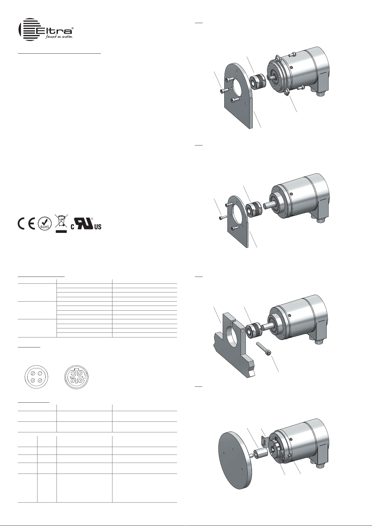
1. Montare il giunto elastico 1sull’encoder.
2. Fissare l’encoder alla flangia di fissaggio cliente 2mediante n.3 viti M4 3oppure tramite n.3
servograffe 4.
3. Fissare la flangia 2al motore o al supporto cliente; verificare che le tolleranze permesse dal giunto
elastico siano rispettate.
1. Montare il giunto elastico 1sull’encoder.
2. Fissare l’encoder alla flangia di fissaggio 2mediante la vite 3.
3. Fissare la flangia 2al motore o al supporto; verificare che le tolleranze permesse dal giunto elastico
siano rispettate.
1. Montare il giunto elastico 1sull’encoder.
2. Fissare l’encoder alla flangia di fissaggio cliente 2mediante n.3 viti M3 3.
3. Fissare la flangia 2al motore o al supporto cliente; verificare che le tolleranze permesse dal giunto
elastico siano rispettate.
1. Accoppiare la boccola di riduzione (se presente) 1 all’albero encoder.
2. Applicare frenafiletti (es. Loctite 243) nei fori della molla 2 e fissarla al corpo encoder tramite n.3
viti M3x4 fornite in dotazione, coppia di chiusura raccomandata 0,4 Nm / 57 Ozin.
3. Accoppiare l’albero encoder con l’albero motore.
4. Fissare la molla 2alla flangia motore cliente con n.2 viti M3 3senza bloccarla.
5. Fissare la ghiera 4 tramite l’apposita vite (chiave a brugola 2,5), coppia di chiusura raccomandata
1,5 Nm / 212 Ozin.
6. Bloccare la molla.
* non in dotazione
** non in dotazione, vedi P/N 94080001
Connettore Pin Funzione
Connettore
PORT 1
1 Tx D+
2 Rx D+
3 Tx D-
4 Rx D-
Connettore
POWER
1 +V DC
2 /
3 0 V
4 /
Connettore
PORT 2
1 Tx D+
2 Rx D+
3 Tx D-
4 Rx D-
Nome led Colore Descrizione funzionalità
LINK 1 arancione e verde (lampeggio) Connessione al bus attiva - attività in entrata
e in uscita sulla PORTA 1
LINK 2 arancione e verde (lampeggio) Connessione al bus attiva - attività in entrata
e in uscita sulla PORTA 2
Error
(led rosso)
Power
(led verde) Significato Causa
Spento Spento Assenza di alimentazione
Spento Acceso Scambio dati, slave e funzionamento ok
Acceso Acceso No connessione con un altro dispositivo
Criterio: assenza scambio dati
- Bus disconnesso
- Master non disponibile / spento
Lampeggio
(1) Acceso
Errore di parametrizzazione, nessuno
scambio di dati
Criterio: scambio di dati corretto.
Tuttavia, lo slave non è passato alla
modalità di scambio dati
- Slave non ancora configurato (o errata
configurazione)
- È stato assegnato un indirizzo di stazione
errato (ma non fuori dal range consentito)
- La configurazione effettiva dello slave
differisce dalla configurazione nominale
(1) Frequenza lampeggio 0,5 Hz, tempo minimo di indicazione 3 s
LED DIAGNOSTICA
200921
Eltra S.p.a. Unipersonale
36040 Sarego - Italy tel. +39 0444 436489 fax. +39 0444 835335
58 C
58 B
1*
2*
4**
3*
1*
3*
2*
1*
2*
3*
58 C
58 F
4
12
3*


