TKE TW45 User manual

OPERATING MANUAL
TW45
Drive
03/2023
6231003860

2 Company and contact information
TK Elevator
BA, TW45 | 6231003860 | 03/2023
Company and contact
information
All rights reserved
© Copyright by TK Aufzugswerke GmbH
Proprietary notice ISO 16016
Printed in Germany
This document – including excerpts – may only be reprinted or otherwise
copied with the express approval in writing of TK Aufzugswerke GmbH.
Any form of duplication, dissemination or storage on data media in any form
that is not authorised by TK Aufzugswerke GmbH represents a violation of
prevailing copyright law and shall lead to legal proceedings.
Subject to change without notice
We expressly reserve the right to make changes of a technical nature for the
purpose of improving our products or enhancing the safety standard – includ-
ing without a separate announcement.
Colour coding
The colour coding of the components used in our documents is exclusively for
documentation purposes.
You can find out about the colours for your products from your TK Aufzug-
swerke GmbH sales partner.
Form of address
In the interest of better legibility, we use exclusively the masculine grammat-
ical form, for example "fireman". At the same time, it always refers to human
genders: male, female, diverse.
Issued by
TK Aufzugswerke GmbH
Bernhäuser Straße 45
73765 Neuhausen a. d. F.
Germany
Tel: +49 7158/12-0
E-mail: [email protected]
Internet: eli.tkelevator.com

Table of contents 3
Table of contents
1 About these instructions. ........................................................................... 6
1.1 Guide to layout. ........................................................................................................................................................... 6
2 Safety. ............................................................................................................ 7
2.1 Warning notes. .............................................................................................................................................................7
2.1.1 Structure. ................................................................................................................................................................ 7
2.1.2 Indications of danger to persons........................................................................................................................ 7
2.1.3 Indication of possible damage to property. ..................................................................................................... 7
2.2 Safety requirements................................................................................................................................................... 8
2.2.1 Area of applicability. .............................................................................................................................................8
2.2.2 Basic requirements for safety.............................................................................................................................8
2.2.3 Obligations of the operating company and installation firm. .......................................................................8
2.2.4 Duties of personnel. ..............................................................................................................................................8
2.2.5 Dangers in handling the drive. ............................................................................................................................9
2.3 Warranty and liability. ...............................................................................................................................................10
2.3.1 Structural modification of the product. .......................................................................................................... 10
2.3.2 Use in line with intended use............................................................................................................................. 10
2.4 10 rules for health and safety at work. ...................................................................................................................11
2.5 Personal protective equipment...............................................................................................................................12
3 Description. ..................................................................................................13
3.1 Standards and legal requirements. ........................................................................................................................13
3.2 Product Group TW Machines..................................................................................................................................13
3.3 Product. .......................................................................................................................................................................13
3.3.1 Machine base frame. ......................................................................................................................................... 20
3.3.2 Motor versions. ....................................................................................................................................................23
3.3.3 Special versions. ..................................................................................................................................................24
3.3.4 Standard version for machine in the machine room. ...................................................................................24
3.3.5 Version with emergency brake, NBS...............................................................................................................24
3.3.6 Version with earthquake safeguard complying with EN81-77. ..................................................................25
3.3.7 Version for machine location in the shaft pit for ISIS1.................................................................................25
3.4 Combination of versions / options........................................................................................................................26
4 Technology.................................................................................................. 27
4.1 Mechanical data........................................................................................................................................................ 27
4.1.1 Gear unit................................................................................................................................................................27
4.1.2 Brake. .....................................................................................................................................................................28
4.1.3 Encoder. ............................................................................................................................................................... 29
4.1.4 Traction sheave................................................................................................................................................... 30
4.1.5 Performance chart. ............................................................................................................................................ 30
4.1.6 Motor versions. ....................................................................................................................................................32
4.1.7 Load data - traction sheave shaft. .................................................................................................................. 34
4.1.8 Load data for upward horizontal / vertical rope pull direction.................................................................. 34
4.1.9 Gear efficiency.....................................................................................................................................................35
4.1.10 Mass moment of inertia. ................................................................................................................................... 36
4.1.11 Weight................................................................................................................................................................... 36
4.1.12 Noise levels. ..........................................................................................................................................................37
4.2 Dimensions................................................................................................................................................................. 38
4.2.1 Machine.................................................................................................................................................................38
TK Elevator
BA, TW45 | 6231003860 | 03/2023

4.2.2 Machine base frame. ..........................................................................................................................................42
5 Transportation and storage. ....................................................................47
5.1 Packaging................................................................................................................................................................... 47
5.2 Transport....................................................................................................................................................................48
5.3 Fork-lift truck transport. .........................................................................................................................................48
5.4 Crane transport.........................................................................................................................................................48
5.5 Checking the delivery. .............................................................................................................................................49
5.6 Intermediate storage................................................................................................................................................50
6 Installation....................................................................................................51
6.1 Setting up the machine base frame.......................................................................................................................51
6.2 Aligning the machine. ...............................................................................................................................................51
6.3 Mounting the frame with rope pulley. .................................................................................................................. 52
6.4 Mounting the rope guard. .......................................................................................................................................54
6.5 Rope pulley on the machine base frame.............................................................................................................. 55
6.6 Shift protection on the machine base frame. .....................................................................................................55
6.7 Electrical connection. ..............................................................................................................................................56
6.7.1 Connecting the machine....................................................................................................................................57
6.7.2 Connecting the motor line.................................................................................................................................58
6.7.3 Connecting the posistor.................................................................................................................................... 59
6.7.4 Connecting the brake. ....................................................................................................................................... 59
7 Work on the product. ............................................................................... 60
7.1 Testing the brake......................................................................................................................................................60
7.2 Replacing the brake...................................................................................................................................................61
7.2.1 Mayr brake............................................................................................................................................................ 61
7.3 Checking the oil level. ..............................................................................................................................................63
7.4 Lubrication.................................................................................................................................................................63
7.5 Checking the backlash.............................................................................................................................................65
7.6 Replacing the traction sheave................................................................................................................................66
7.7 Replacing the motor.................................................................................................................................................68
7.8 Replacing the encoder.............................................................................................................................................69
7.9 Checking for grease/oil leakage. ...........................................................................................................................70
7.10 Blocking clamp...........................................................................................................................................................71
8 Commissioning........................................................................................... 72
8.1 Work steps. ................................................................................................................................................................ 72
8.2 Emergency operation. ............................................................................................................................................. 72
9 Maintenance. ..............................................................................................74
9.1 Standstill maintenance............................................................................................................................................ 74
10 Appendix...................................................................................................... 75
10.1 Tightening torques. .................................................................................................................................................. 75
10.2 Manufacturer information. ..................................................................................................................................... 75
10.2.1 Wachendorff encoder WDG100H_38-1024 - Data sheet............................................................................77
10.2.2 Verification of traction sheave calculation.....................................................................................................78
10.2.3 mayr ROBA-duplostop Size 125 brake - installation and operating manual............................................79
10.2.4 mayr ROBA-duplostop Size 500 - 1800 brake - installation and operating manual. ........................... 95
10.2.5 SKINTOP MS-SC Mounting instructions........................................................................................................111
10.2.6 Wachendorff encoder WDG100H--xx-yyyy-ABN-I05-K3-D56 - assembly instructions.....................112
4 Table of contents
TK Elevator
BA, TW45 | 6231003860 | 03/2023

Table of contents 5
10.2.7 Drehgeber Wachendorf WDG 100H - Datenblatt. .......................................................................................113
10.2.8 Drehgeber Wachendorf WDG 100H-XX-YYYY - Montageanleitung. ...................................................... 125
10.2.9 Drehgeber Wachendorf WDG 100H-38-2048.pdf......................................................................................126
TK Elevator
BA, TW45 | 6231003860 | 03/2023

6
About these instructions
Guide to layout
TK Elevator
BA, TW45 | 6231003860 | 03/2023
1 About these instructions
1.1 Guide to layout
Sequence of actions involving several steps
üRequirement for the sequence of actions (optional).
1. First action step.
2. Second action.
Interim result (optional)
3. Third action step.
Result of action (optional)
Sequence of actions involving independent steps
Action step.
Action step.
Action step.
Information
i
Information must always be read and followed.
Reference
Chap.1P.6
List
▪Top item of a list
– Sub-item of a list
– Sub-item of a list
▪Top item of a list
▪Top item of a list

Safety
Warning notes 7
TK Elevator
BA, TW45 | 6231003860 | 03/2023
2 Safety
2.1 Warning notes
▪Warning notes are intended for the protection of persons and property.
▪Warning notes must be read and observed by every person who works on
the product.
▪Warning notes precede activities that pose a hazard for people and the
product.
2.1.1 Structure
SIGNAL WORD AND SIGNAL COLOUR
Type and source of danger
Consequences if danger disregarded.
Measures to avert the danger.
2.1.2 Indications of danger to persons
DANGER
Danger with a high degree of risk!
If ignored, leads to death or serious injury.
Read and comply with the warning.
WARNING
Danger with a high degree of risk!
If ignored, may lead to death or serious injury.
Read and comply with the warning
CAUTION
Danger with a low degree of risk!
If ignored, may lead to minor or moderate injury.
Read and comply with the warning.
2.1.3 Indication of possible damage to property
NOTICE
Hazard with possible damage to property!
May lead to product function impairments or function loss.
Read and comply with the warning.

8
Safety
Safety requirements
TK Elevator
BA, TW45 | 6231003860 | 03/2023
2.2 Safety requirements
This document contains important information for safe operation of the
product.
Keep this document and all other applicable documents at the location of
use for the entire working life of the product.
2.2.1 Area of applicability
This document applies only to the product described here.
Other applicable documents
▪International occupational health and safety regulations
2.2.2 Basic requirements for safety
▪All existing safety devices are to be tested regularly in accordance with
the maintenance schedule.
▪This document, in particular the chapter entitled "Safety", together with
the warnings and all other applicable documents, must be followed by all
persons who work with the product.
▪In addition to this document, the rules at the location of use with regard to
environmental protection and the occupation health and safety and acci-
dent prevention regulations must be followed.
▪All safety and hazard warnings on the installation must be kept in legible
condition.
▪Safety information and instructions required by law must be displayed to
users in such a way that they are clearly visible.
▪A requirement for safe handling and non-disruptive operation of this
product is knowledge of the fundamental safety regulations.
2.2.3 Obligations of the operating company and installation
firm
Only deploy trained and instructed qualified personnel.
Provide personnel with the required personal protective equipment.
Check personnel at regular intervals to ensure that they follow safety-
conscious work practices and comply with national provisions.
Make all other applicable documents as well as this document available to
personnel.
2.2.4 Duties of personnel
Clearly establish all areas of responsibility prior to any activity.
Always wear the personal protective equipment made available to you.
Prior to work, make people aware of the dangers of electrical current.
Safety
Safety requirements 9
TK Elevator
BA, TW45 | 6231003860 | 03/2023
2.2.5 Dangers in handling the drive
DANGER
Residual voltage after switching off the elevator installation!
Electric shock that can lead to death or severe injury.
Perform work on energised parts of the drive only after the waiting
period and/or when the DC link voltage is less than 60 V (check with a
measuring instrument)
WARNING
Inadequate connection
Electric shock. Damage to drive.
Earth the motor and brake magnet in accordance with country-specific
regulations.
Electrical connections must correspond to at least the protection class in
accordance with the name plate and/or required country-specific protec-
tion class.
WARNING
Contact with rotating or moving parts!
Entanglement of clothing or body parts can lead to crushing or even loss of
limbs.
Maintain an adequate distance to rotating and moving parts, for example
traction sheave, ropes.
Wear tight-fitting clothing.
Make sure you assume a firm stance.
▪The drive may only be operated in a closed machine room or secured
shaft.
▪The machine may only be operated with the cover and rope guard fitted to
the traction sheave.
▪The drive is not suitable for operation in explosive or aggressive atmo-
spheres.
▪On entering the machine room, adequate safety clearance to all rotating
parts is to be maintained.
▪In the event of improper use of the machine, there is a risk of personal in-
jury or to the life of the user or third parties, or impairment on the as-
sembly or other assets can arise. Malfunctions that can adversely affect
safety must be rectified immediately.
▪It must be ensured that a fault generated by the encoder, the brake or the
brake control system is detected by the elevator control system or fre-
quency inverter. The control system must immediately place the elevator
in a safe state.
▪The elevator installation must ensure that emergency braking by the
mechanical brake system takes place in the following cases:
– Uncontrolled movement out of the stopping zone

10
Safety
Warranty and liability
TK Elevator
BA, TW45 | 6231003860 | 03/2023
– Failure of the inverter (due to short circuit with triggering of the fuse)
▪The elevator installation must be fitted with a safety device complying
with EN81 or A17 that detects exiting the elevator car with the door
opened and initiates suitable measures.
2.3 Warranty and liability
The "General Terms of Sale and Delivery" of TK Aufzugswerke GmbH apply.
Warranty and liability claims in the event of personal injury and material dam-
age shall be excluded if they arise due to at least one of the following causes:
▪Improper use that is not in line with the intended purpose of the product
▪Incorrect installation, commissioning, operation and maintenance of the
product
▪Operation of the product with defective or inoperative safety and/or pro-
tection devices
▪Non-observance of the instructions in the operating manual with regard to
transport, storage, installation, commissioning, operation and mainten-
ance
▪Structural modification to the product without agreement or approval
▪Modification to product features without agreement or approval
▪Inadequate monitoring of parts that are subject to wear
▪Repairs that are carried out improperly
▪Cases of catastrophe due to third-party interference or force majeure
▪Use of non-approved auxiliary materials and operating fluids
2.3.1 Structural modification of the product
The product is configured in the factory and delivered ready for operation.
If changes are made to the product, the entire warranty of TK Aufzugswerke
GmbH shall become null and void.
2.3.2 Use in line with intended use
The product has been constructed using state-of-the-art technology and in
line with the recognised technical safety regulations. It may only be used in
accordance with its intended use and when the technical safety devices are
free from defects. Any other or additional form of use shall be regarded as
non-compliant with the intended use. TK Aufzugswerke GmbH shall not be li-
able for any damage arising from such use and any damage arising due to op-
erator errors.
In order to comply with the intended use of the product:
▪Use the product as a Drive of elevators only
▪Read and comply with the document, in particular the chapter entitled
"Safety", together with the warnings and all other applicable documents
▪Comply with the commissioning instructions, the installation description
as well as the required inspection and maintenance work

Safety
10 rules for health and safety at work 11
TK Elevator
BA, TW45 | 6231003860 | 03/2023
2.4 10 rules for health and safety at work
The international rules for occupational health and safety can also be found
on our internet platform ELI for download at: https://eli.tkelevator.com/sup-
port/occupational-safety-health

12
Safety
Personal protective equipment
TK Elevator
BA, TW45 | 6231003860 | 03/2023
2.5 Personal protective equipment
Danger Cause Risks Remedy Equipment
▪Unprotected shaft Falling Safety har-
ness
▪WARNING!
Do not walk underneath suspended
loads
▪Falling tools
▪Transport of heavy loads
▪Sharp-pointed objects
Head injury Head protec-
tion
▪WARNING!
Do not walk underneath suspended
loads
▪Falling tools
▪Transport of heavy loads
▪Sharp-pointed objects
Danger of crushing in the
foot area
Cut or stab injury in the
foot area
Foot protec-
tion
▪Sharp objects
▪Mechanical parts
▪Sharp-pointed objects
▪Caustic substances
Danger of crushing in the
hand area
Stab injury in the hand area
Acid/alkali burns
Protective
gloves
▪Severe noise pollution Noise damage Ear protec-
tion
▪Flying parts
▪Flying particles
▪Laser beams
▪Emissions of optical rays
Eye injury
Loss of sight/blinding
Protective
goggles
▪Electrical voltage Electric shock
Enable
source of en-
ergy

Description
Standards and legal requirements 13
TK Elevator
BA, TW45 | 6231003860 | 03/2023
3 Description
3.1 Standards and legal requirements
The product complies with the following regulations:
▪DIN EN 81-20:2020-06
▪DIN EN 81-50:2020-06
▪DIN EN 81-77:2019-01
i
For operation in line with standards, the elevator installation must comply with
each standard.
3.2 Product Group TW Machines
The designation of this series (successor generation of W series) is composed
of the combination of TK Elevator, Wormgear (TW) and a figure for the main
performance point (e.g. Q = 1600 kg → 160) of the machine, as well as an in-
dicator of the generation (e.g. "B").
As part of further technical development, these machines are designed com-
pletely with low-friction rolling bearings.
The use of a synthetic gear oil (polyalkylene glycol with additives) not only in-
creases the power density and the gear efficiency, but also extends the oil
change intervals.
3.3 Product
The TW45C machine (TK Elevator, Wormgear / Q = 450 kg / generation C) is
used within the framework of the TW model series (machines with worm
gears, anti-friction bearings, lubrication with synthetic gear oil) for traction el-
evators in the lower range of performance.
The TW45C has been available since May 2011 and it differs from the previous
version TW45B in that there are modified anti-friction bearings with optimised
sealing (stroke unit on worm shaft).
The TW45C machine, conceived for systems with rated load 450 kg at 1.0 /
1.25 m/s, consists of a worm gear with integrated service brake, overhung
traction sheave, flange-connected three-phase motor in IMB5/V1 structural
shape as well as the optionally possible emergency brake, NBS.
The corresponding production, assembly and assignment of the components
means that the versions of the machine described below are possible:
▪Vertical upright motor position; traction sheave position on left; with /
without emergency brake system, NBS – for machine location in the ma-
chine room.
▪Horizontal motor position; traction sheave position on left / on right; with /
without emergency brake system, NBS – for machine location in the ma-
chine room.

14
Description
Product
TK Elevator
BA, TW45 | 6231003860 | 03/2023
▪ISIS1 version: Horizontal motor position; traction sheave position on left /
right, with emergency brake system, NBS – for location in the shaft pit.
The machine is exclusively available with frequency-controlled motors (V3F).
TW45C in horizontal version for installation in the machine room
Fig.1 ATR_2_21_0027_0
Item Designation Item Designation
1 Rope guard 2 Tension disc on traction sheave
shaft with screwed connection
3 Traction sheave 4 Gear
5 Transport eyebolt 6 Brake release lever
7
Motor terminal box, including in-
termediate terminal connection
for brake
8 Service brake
9 Encoder 10 Handwinding wheel
11 Motor
Installation in the machine room / vertical motor position IMV1
Fig.2 ATR_2_21_0028_0

Description
Product 15
TK Elevator
BA, TW45 | 6231003860 | 03/2023
Item Designation Item Designation
1Driving gear (vertical motor pos-
ition) 2Traction sheave (D440 / D520 /
D590)
3
Motor (version with terminal box
for connection of the service
brake)
4
Service brake Mayr
RSZ125-2x50 Nm, including
mounted lever for manual re-
lease
5 Encoder 6 Handwinding wheel (D270)
7 Rope guard (adjustable) 8 Oil drain (3/4")
9Oil filling hole and ventilation
(R3/4") 10 Oil level monitoring (gauge
glass)
11
Traction sheave mounting (ten-
sion disc with screwed connec-
tion)
12
Motor connection
(M16x1.5 / M25x1.5)
Brake connection
(2x M16x1.5)
13 Transport eyebolts 14 Mounting surface for machine
base frame

16
Description
Product
TK Elevator
BA, TW45 | 6231003860 | 03/2023
Installation in the machine room / horizontal motor position
IMB5
Fig.3 ATR_2_21_0029_0
Item Designation Item Designation
1Driving gear (horizontal motor
position) 2Traction sheave (D440 / D520 /
D590)
3
Motor
(version with terminal box for
connection of the service brake)
4
Service brake Mayr
RSZ125-2x50 Nm, including
mounted lever for manual re-
lease
5 Actual-value sensor 6 Handwinding wheel (D270)
7 Rope guard (adjustable) 8 Oil drain (R3/4")
9Oil filling hole and ventilation
(R3/4") 10 Oil level monitoring (gauge
glass)
11
Traction sheave mounting (ten-
sion disc with screwed connec-
tion)
12
Motor connection (M16x1.5 /
M25x1.5)
Brake connection (2 M16x1.5)
13 Transport eyebolt 14 Mounting surface for machine
base frame

Description
Product 17
TK Elevator
BA, TW45 | 6231003860 | 03/2023
Installation in the machine room / with emergency brake system,
NBS (shown with machine in horizontal motor position)
Fig.4 ATR_2_21_0030_0
Item Designation Item Designation
1Disc brake - emergency brake
system, NBS 2 Cover plate for brake
3Socket wrench for manual re-
lease 4Screws for manual release
(screw head marked in red)
5Brake test switch with connec-
tion line 6 Connection line, brake voltage
7 Protective cover for brake

18
Description
Product
TK Elevator
BA, TW45 | 6231003860 | 03/2023
Machine room with horizontal rope departure direction (shown is
the left traction sheave position / horizontal motor position)
Fig.5 ATR_2_12_0105_0
The machine contains only the components for the rope guard of the top rope
line. To assist installation of these components, the bearing bracket on the
traction sheave side has been fitted at the plant rotated by 60°. The hori-
zontal rope departure direction is possible in both directions (opposing the
motor and/or towards the motor with horizontal motor position). With a ver-
tical motor position, both horizontal directions are also possible. The top rope
guard can be adjusted +/- 15° in relation to the horizontal. The additional com-
ponents required for the rope guard of the bottom rope line and/or in the area
between the rope entry and departure points required in accordance with
EN81-1:1998 and/or EN81-20/5.5.7 are not included in the scope of supply of
the machine and must be fitted on the machine base frame depending on the
order.
Machine room with earthquake safeguard complying with
EN81-77 (shown in the left traction sheave position / vertical
motor position and earthquake safeguard complying with
EN81-77)
Fig.6 ATR_2_12_0106_0
Description
Product 19
TK Elevator
BA, TW45 | 6231003860 | 03/2023
Item Designation Item Designation
1Traction sheave (D440 / D520 /
D590) 2Earthquake safeguard comply-
ing with EN81-77
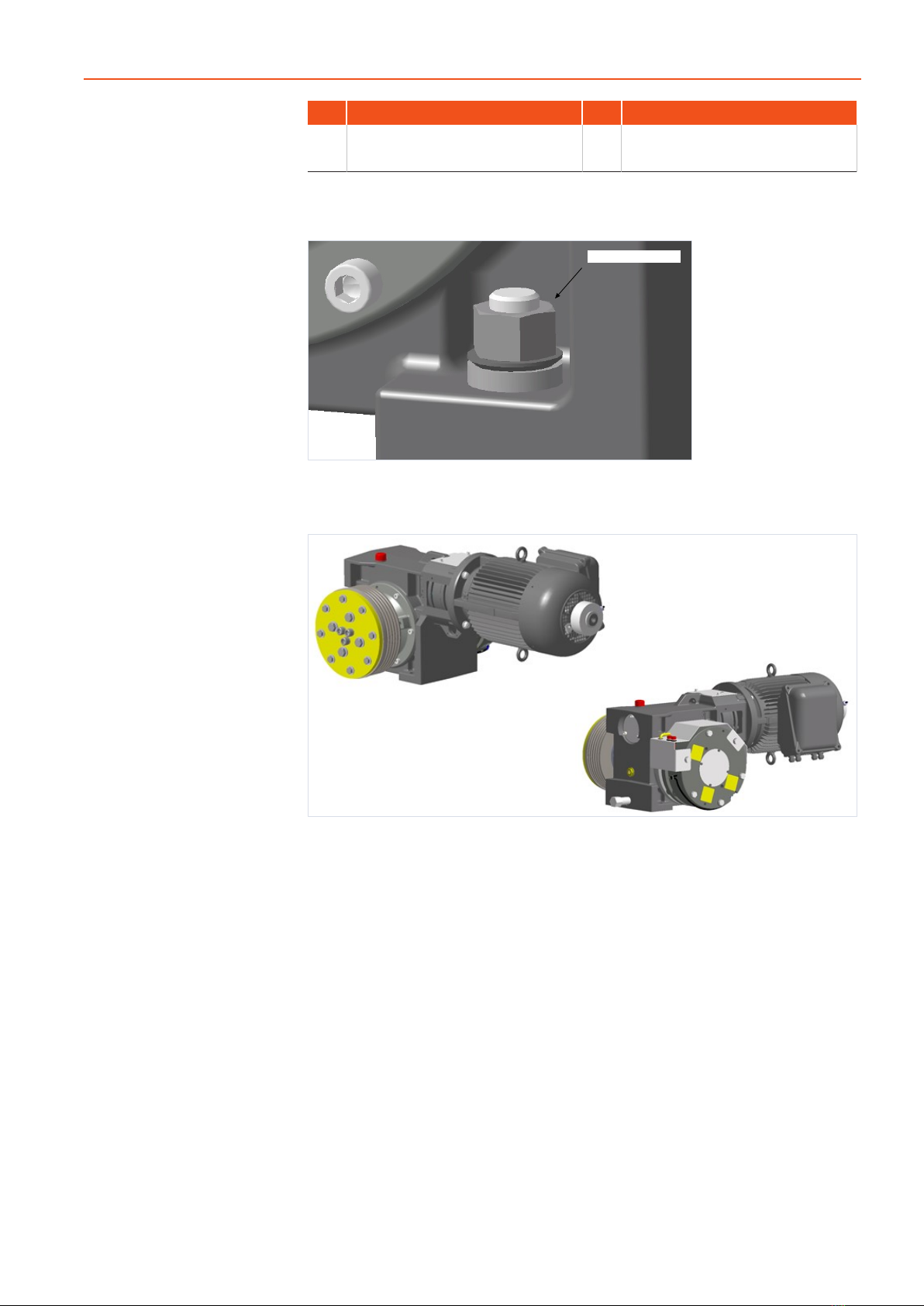
Special version SA1 (modified mounting of the machine,
including compensation washers)
M16-10.9 - 190 NM
Fig.7 ATR_2_12_0151_1
ISIS1 version (MRL – machine in the shaft pit)
Fig.8 ATR_2_12_0149_0
The machine has a "horizontal" motor position.
The position of the motor terminal box is at the side opposite the traction
sheave.
In general, the ISIS1 version of the machine has the NBS emergency brake
system.
The traction sheave shown in the diagram is not included in the scope of sup-
ply. It is made available by TKE-NA.
The components for the rope guard and the fastening elements for the ma-
chine on the machine base frame are also made available by TKE-NA.
The connection lines of the service and emergency brakes are routed through
the enlarged motor terminal box and routed by means of conduits into a mo-
tor interface box (MIB).
The motors made by EMOD are voltage interchangeable 230 / 460 V and
have no handwinding wheel. The motors have CSA certification.

20
Description
Product
TK Elevator
BA, TW45 | 6231003860 | 03/2023
Deviating from the standard version, the versions of the service brake and
emergency brake are operated with a lower voltage of 110 / 55 V DC. Both
brakes have CSA certification.
The service brake with 2x50 Nm is regarded as a 100 Nm brake (ASME A17.1)
for this use case.
The encoder used is a Wachendorff WDG100-2x2048 TTL with a 3 m line
length.
3.3.1 Machine base frame
Various machine base frame versions are possible. Consult the general ar-
rangement drawings.
The machine base frames with / without rope pulley described below are in-
tended for installation of the machine in the machine room above the shaft.
The machine base frame without rope pulley consists of three plated-edge
longitudinal brackets with two welded face plates. The hole pattern in the ma-
chine base frame permits a shift of the machine on the machine base frame in
the hole distance 40/50 mm.
The machine base frame with rope pulley consists of the machine base frame
without rope pulley as an upper frame part and bolted-on supports for the
rope pulley bearings and insulation elements.
With this machine base frame, there is the possibility for a right-hand or left-
hand configuration of the rope pulley position with the corresponding installa-
tion of the supports.
Setup
As a rule, the machine base frame is set up on insulation elements (rubber
blocks) either on a machine base frame support (steel support) or directly on
the machine room floor.
The components for the rope guard in accordance with EN81-1/9.7 and
EN81-20/5.5.7 are part of the machine.
Weight of machine base frame
Version of rope pulley [mm] Weight, including rope pulley [kg]
D360 140
D450 170
Weight of machine base frame without rope pulley: 50 kg
ASY TW45B O SR machine base frame
The TW45B O SR machine base frame (shown with machine in vertical motor
position and traction sheave position on left) in version without rope pulley is
used for:
▪Installations with rope suspension 1:1 and direct rope departure with a rope
distance elevator car - counterweight ASL ≤ (DT + 100) mm with traction
sheave diameter 520 or 590 mm
▪Installations with rope suspension 2:1 and traction sheave diameters 440,
520, or 590 mm
Table of contents


