Instron 3119-600 Series User manual
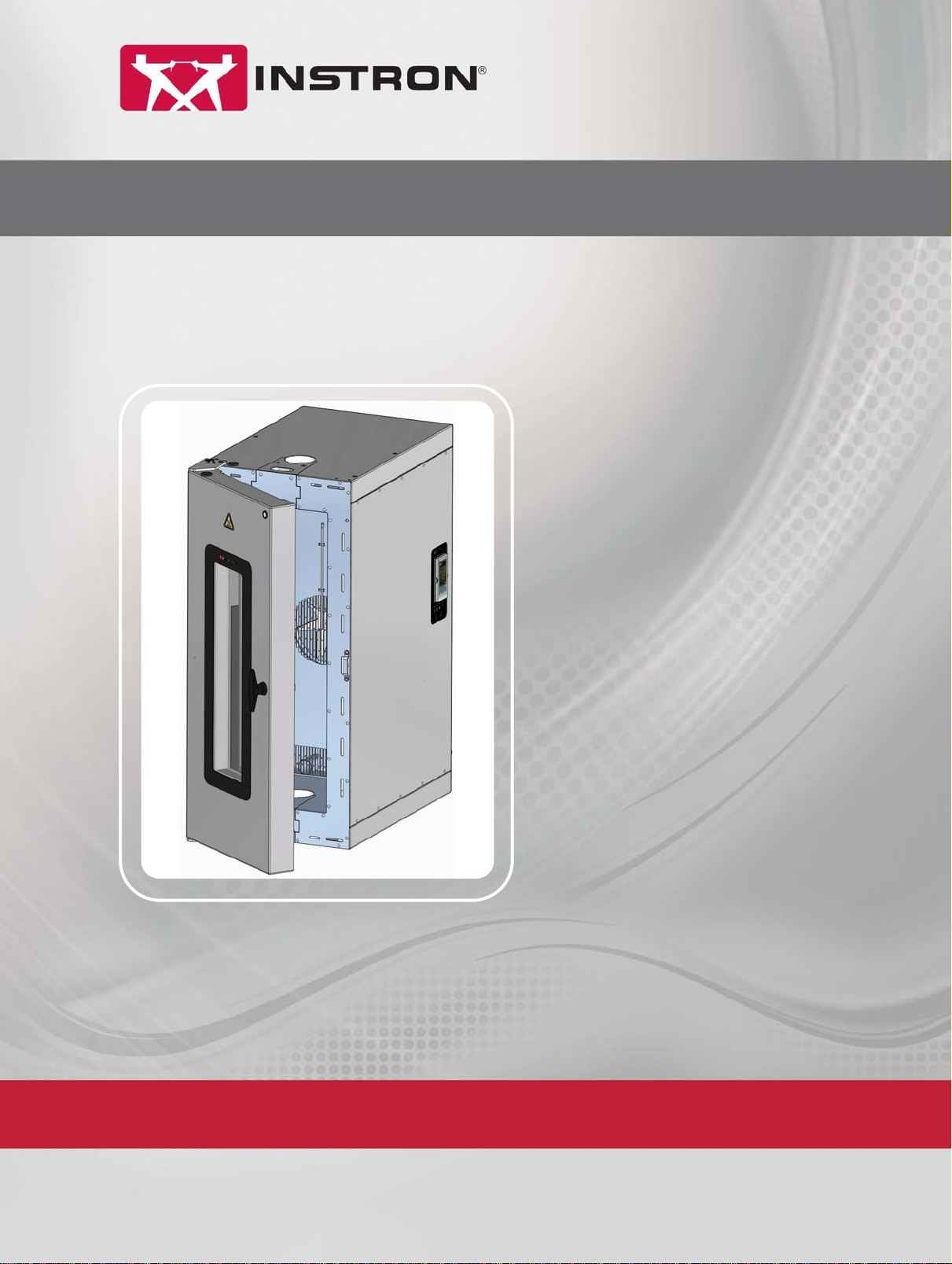
3119-600 Series Temperature Controlled Chambers
Operating Instructions M55-16547-EN Revision E
The difference is measurable
®

Electromagnetic Compatibility
Where applicable, this equipment is designed to comply with International Electromagnetic
Compatibility (EMC) standards. To ensure reproduction of this EMC performance, connect this
equipment to a low impedance ground connection. Typical suitable connections are a ground
spike or the steel frame of a building.
Proprietary Rights Notice
This document and the information that it contains are the property of Illinois Tool Works Inc.
(ITW). Rights to duplicate or otherwise copy this document and rights to disclose the document
and the information that it contains to others and the right to use the information contained
therein may be acquired only by written permission signed by a duly authorized officer of ITW.
Trademarks
Instron®is a registered trademark of Illinois Tool Works Inc. (ITW). Other names, logos, icons
and marks identifying Instron products and services referenced herein are trademarks of ITW
and may not be used without the prior written permission of ITW.
Other product and company names listed are trademarks or trade names of their respective
companies.
Original Instructions
Copyright © 2017 Illinois Tool Works Inc. All rights reserved.
All of the specifications shown in this document are subject to change without notice.
Worldwide Headquarters
Instron
825 University Avenue
Norwood,
MA 02062-2643
United States of America
European Headquarters
Instron
Coronation Road
High Wycombe,
Bucks HP12 3SY
United Kingdom

3
Preliminary Pages
Product Support: www.instron.com
Table of Contents
Chapter 1 Introduction . . . . . . . . . . . . . . . . . . . . . . . . . . . . . . . . . . . . . . . . . . . . . . . . 7
About 3119-600 Series Chambers . . . . . . . . . . . . . . . . . . . . . . . . . . . . . . . . . . . . . . . . . . . . . 7
About this Manual . . . . . . . . . . . . . . . . . . . . . . . . . . . . . . . . . . . . . . . . . . . . . . . . . . . . . . . . . . 9
Additional Chamber Documentation . . . . . . . . . . . . . . . . . . . . . . . . . . . . . . . . . . . . . . . . . . . . 9
Product Labelling . . . . . . . . . . . . . . . . . . . . . . . . . . . . . . . . . . . . . . . . . . . . . . . . . . . . . . . . . . 10
System Hazard Warning Labels. . . . . . . . . . . . . . . . . . . . . . . . . . . . . . . . . . . . . . . . . . . 10
Product Identification Label. . . . . . . . . . . . . . . . . . . . . . . . . . . . . . . . . . . . . . . . . . . . . . 10
Control Panel and Rear Input Panel Labelling . . . . . . . . . . . . . . . . . . . . . . . . . . . . . . . 10
Chapter 2 Safety . . . . . . . . . . . . . . . . . . . . . . . . . . . . . . . . . . . . . . . . . . . . . . . . . . . . 11
General Safety Precautions . . . . . . . . . . . . . . . . . . . . . . . . . . . . . . . . . . . . . . . . . . . . . . . . . . 11
Warning Signs Used . . . . . . . . . . . . . . . . . . . . . . . . . . . . . . . . . . . . . . . . . . . . . . . . . . . . . . . . 12
Electrical . . . . . . . . . . . . . . . . . . . . . . . . . . . . . . . . . . . . . . . . . . . . . . . . . . . . . . . . . . . . . . . . . 13
Thermal Contact . . . . . . . . . . . . . . . . . . . . . . . . . . . . . . . . . . . . . . . . . . . . . . . . . . . . . . . . . . . 14
Specimens. . . . . . . . . . . . . . . . . . . . . . . . . . . . . . . . . . . . . . . . . . . . . . . . . . . . . . . . . . . . . . . . 14
Cryogenic Gases: Asphyxiation and Toxicity . . . . . . . . . . . . . . . . . . . . . . . . . . . . . . . . . . . . . 15
Glass Fibre Insulation. . . . . . . . . . . . . . . . . . . . . . . . . . . . . . . . . . . . . . . . . . . . . . . . . . . . . . . 15
High Pressure Gases . . . . . . . . . . . . . . . . . . . . . . . . . . . . . . . . . . . . . . . . . . . . . . . . . . . . . . . 16
Rotating Parts . . . . . . . . . . . . . . . . . . . . . . . . . . . . . . . . . . . . . . . . . . . . . . . . . . . . . . . . . . . . . 16
Physical Testing Machine. . . . . . . . . . . . . . . . . . . . . . . . . . . . . . . . . . . . . . . . . . . . . . . . . . . . 16
Material Safety Data Sheets . . . . . . . . . . . . . . . . . . . . . . . . . . . . . . . . . . . . . . . . . . . . . . . . . 17
Chapter 3 Function of Controls and Indicators. . . . . . . . . . . . . . . . . . . . . . . . . . . . 19
Chamber Door. . . . . . . . . . . . . . . . . . . . . . . . . . . . . . . . . . . . . . . . . . . . . . . . . . . . . . . . . . . . . 19
Power Indicator . . . . . . . . . . . . . . . . . . . . . . . . . . . . . . . . . . . . . . . . . . . . . . . . . . . . . . . . 19
Door Handle . . . . . . . . . . . . . . . . . . . . . . . . . . . . . . . . . . . . . . . . . . . . . . . . . . . . . . . . . . 19
Control Panel Buttons and Indicators . . . . . . . . . . . . . . . . . . . . . . . . . . . . . . . . . . . . . . . . . . 20
Rear Input Panel Connections and Labels . . . . . . . . . . . . . . . . . . . . . . . . . . . . . . . . . . . . . . 22
Removable Wedges . . . . . . . . . . . . . . . . . . . . . . . . . . . . . . . . . . . . . . . . . . . . . . . . . . . . . . . . 24
Removing the Wedges . . . . . . . . . . . . . . . . . . . . . . . . . . . . . . . . . . . . . . . . . . . . . . . . . . 24
Replacing the Wedges . . . . . . . . . . . . . . . . . . . . . . . . . . . . . . . . . . . . . . . . . . . . . . . . . . 24

Preliminary Pages
4M55-16547-EN
Chapter 4 Operating the Chamber . . . . . . . . . . . . . . . . . . . . . . . . . . . . . . . . . . . . . 25
Getting Started . . . . . . . . . . . . . . . . . . . . . . . . . . . . . . . . . . . . . . . . . . . . . . . . . . . . . . . . . . . . 26
Opening and Closing the Chamber Door. . . . . . . . . . . . . . . . . . . . . . . . . . . . . . . . . . . . 27
Switching On the Chamber. . . . . . . . . . . . . . . . . . . . . . . . . . . . . . . . . . . . . . . . . . . . . . . 28
Enabling Low Speed Fan Mode . . . . . . . . . . . . . . . . . . . . . . . . . . . . . . . . . . . . . . . . . . . 28
Home Page . . . . . . . . . . . . . . . . . . . . . . . . . . . . . . . . . . . . . . . . . . . . . . . . . . . . . . . . . . . 29
Checking Settings . . . . . . . . . . . . . . . . . . . . . . . . . . . . . . . . . . . . . . . . . . . . . . . . . . . . . . 29
Switching the Chamber Light On and Off . . . . . . . . . . . . . . . . . . . . . . . . . . . . . . . . . . . 29
Heating or Cooling to a Temperature Setpoint. . . . . . . . . . . . . . . . . . . . . . . . . . . . . . . . . . . 30
About the Temperature Setpoint . . . . . . . . . . . . . . . . . . . . . . . . . . . . . . . . . . . . . . . . . . 30
Stopping Heating or Cooling . . . . . . . . . . . . . . . . . . . . . . . . . . . . . . . . . . . . . . . . . . . . . . . . . 31
Returning the Chamber to Ambient Temperature . . . . . . . . . . . . . . . . . . . . . . . . . . . . 31
Shutting Down the Chamber . . . . . . . . . . . . . . . . . . . . . . . . . . . . . . . . . . . . . . . . . . . . . . . . . 33
Preventive Maintenance . . . . . . . . . . . . . . . . . . . . . . . . . . . . . . . . . . . . . . . . . . . . . . . . . . . . 34
Changing the Eurotherm 3208 Controller Menu . . . . . . . . . . . . . . . . . . . . . . . . . . . . . . . . . 35
Changing the Alarm Settings . . . . . . . . . . . . . . . . . . . . . . . . . . . . . . . . . . . . . . . . . . . . . . . . . 36
Auxiliary Alarm. . . . . . . . . . . . . . . . . . . . . . . . . . . . . . . . . . . . . . . . . . . . . . . . . . . . . . . . . . . . . 36
Resetting a Tripped Alarm . . . . . . . . . . . . . . . . . . . . . . . . . . . . . . . . . . . . . . . . . . . . . . . . . . . 37
Changing the Temperature Units. . . . . . . . . . . . . . . . . . . . . . . . . . . . . . . . . . . . . . . . . . . . . . 37
Changing the Ramp Rate . . . . . . . . . . . . . . . . . . . . . . . . . . . . . . . . . . . . . . . . . . . . . . . . . . . . 38
Using the Timer/Programmer . . . . . . . . . . . . . . . . . . . . . . . . . . . . . . . . . . . . . . . . . . . . . . . . 39
About the Programmer . . . . . . . . . . . . . . . . . . . . . . . . . . . . . . . . . . . . . . . . . . . . . . . . . . 41
Running, Holding or Stopping a Program . . . . . . . . . . . . . . . . . . . . . . . . . . . . . . . . . . . 42
Connecting the Chamber to a Computer . . . . . . . . . . . . . . . . . . . . . . . . . . . . . . . . . . . . . . . 43
Analog Output . . . . . . . . . . . . . . . . . . . . . . . . . . . . . . . . . . . . . . . . . . . . . . . . . . . . . . . . . . . . . 45
Fault Finding . . . . . . . . . . . . . . . . . . . . . . . . . . . . . . . . . . . . . . . . . . . . . . . . . . . . . . . . . . . . . . 45
Appendix A Additional Configuration Parameters . . . . . . . . . . . . . . . . . . . . . . . . . . 49
Introduction. . . . . . . . . . . . . . . . . . . . . . . . . . . . . . . . . . . . . . . . . . . . . . . . . . . . . . . . . . . . . . . 49
Getting Started . . . . . . . . . . . . . . . . . . . . . . . . . . . . . . . . . . . . . . . . . . . . . . . . . . . . . . . . . . . . 49
Changing User Levels . . . . . . . . . . . . . . . . . . . . . . . . . . . . . . . . . . . . . . . . . . . . . . . . . . . . . . . 50
3208 Controller Access Level Configuration . . . . . . . . . . . . . . . . . . . . . . . . . . . . . . . . 50
Changing from Level 1 to Level 2 . . . . . . . . . . . . . . . . . . . . . . . . . . . . . . . . . . . . . . . . . 51

5
Preliminary Pages
Product Support: www.instron.com
Setting Level 2 Parameters . . . . . . . . . . . . . . . . . . . . . . . . . . . . . . . . . . . . . . . . . . . . . . . . . . 51
Autotune . . . . . . . . . . . . . . . . . . . . . . . . . . . . . . . . . . . . . . . . . . . . . . . . . . . . . . . . . . . . . . . . . 53
Control Parameters . . . . . . . . . . . . . . . . . . . . . . . . . . . . . . . . . . . . . . . . . . . . . . . . . . . . . . . . 54
Run Recipe (Factory Reset and DC Output Calibration) . . . . . . . . . . . . . . . . . . . . . . . . . . . 55
Resetting the Chamber to Factory Defaults . . . . . . . . . . . . . . . . . . . . . . . . . . . . . . . . . 55
Calibrating an External Device using the Controller’s DC Output . . . . . . . . . . . . . . . . 55
DC Output Configuration . . . . . . . . . . . . . . . . . . . . . . . . . . . . . . . . . . . . . . . . . . . . . . . . . . . . 56
Appendix B Hints and Tips for Using Chambers. . . . . . . . . . . . . . . . . . . . . . . . . . . . . 57
Minimising Energy and Coolant Consumption . . . . . . . . . . . . . . . . . . . . . . . . . . . . . . . . . . . 57
Looking after your Equipment . . . . . . . . . . . . . . . . . . . . . . . . . . . . . . . . . . . . . . . . . . . . . . . . 58
Ease of Use . . . . . . . . . . . . . . . . . . . . . . . . . . . . . . . . . . . . . . . . . . . . . . . . . . . . . . . . . . . . . . . 59
Optimising Your Testing . . . . . . . . . . . . . . . . . . . . . . . . . . . . . . . . . . . . . . . . . . . . . . . . . . . . . 59

Preliminary Pages
6M55-16547-EN

7
Product Support: www.instron.com
Chapter 1
Introduction
This chapter introduces the chamber and contains the following sections:
•About 3119-600 Series Chambers . . . . . . . . . . . . . . . . . . . . . . . . . . . . . . . . . . . . . 7
•About this Manual . . . . . . . . . . . . . . . . . . . . . . . . . . . . . . . . . . . . . . . . . . . . . . . . . . . 9
•Additional Chamber Documentation . . . . . . . . . . . . . . . . . . . . . . . . . . . . . . . . . . . . 9
•Product Labelling. . . . . . . . . . . . . . . . . . . . . . . . . . . . . . . . . . . . . . . . . . . . . . . . . . . 10
About 3119-600 Series Chambers
The Instron 3119-600 Series environmental chamber provides a means of carrying out
materials tests in an accurately controlled air temperature environment.
The chamber (see Figure 1) is designed to fit between the columns of a physical testing
machine. Pullrod access is provided on the top and bottom surfaces of the chamber and
an integrated control panel provides the user interface for all of the chamber functions.
The chamber is supplied with removable wedges to allow easy removal of the chamber
from the test area without dismantling the load string.
Different height chambers are available; these are selected to suit the required
application. All chambers operate from ambient temperature to the top of their
temperature range. An optional cooling module can be supplied if testing at below
ambient temperatures is required.
The chamber window is heated to keep it frost free at below ambient temperatures. The
limit of this feature is -30°C. Below this limit window clarity may degrade, however,
depending on ambient temperature, humidity and other influencing factors, the central
third of the window is expected to remain frost free.
The chamber can be mounted onto the load frame in a fixed position or on a roller
mounting assembly, which enables the chamber to be moved clear of the working area.
Refer to the Pre-Installation manual for mounting options.

Chapter: Introduction
8M55-16547-EN
Caution
Eyebolts are included with the chamber to enable initial positioning and installation
of the chamber only.
After installation, certification and maintenance of the eyebolts as lifting equipment
become the customer's responsibility. Refer to relevant local legislation.
Figure 1. 3119-600 Chamber Components
Heated
Window
Door
Handle
Upper
Removable
Wedge
Power
Indicator
High
Temperature
Warning
Label
Circulating
Fan
Internal Light
(Not Shown)
Lower
Removable
Wedge
Pullrod Port
Control
Panel

9
About this Manual
Product Support: www.instron.com
About this Manual
This manual contains the information necessary to operate the chamber by giving safety
information, describing the controls and providing detailed procedures for general
operation.
Further to general operating procedures, Appendix A provides details about additional
configuration procedures. Hints and tips on how to get the best from your chamber are
provided in Appendix B.
Caution
Other than the procedures prescribed in this manual, do not adjust the configuration
parameters of the controller. Configuration parameter errors can seriously impair the
performance of the controller or cause damage to the chamber.
The procedures detailed in this manual have been validated by Instron. You are advised
to use only these specific procedures and in the manner documented. You are advised
not to change any parameters of the controller other than those detailed in this manual.
Key combinations and/or sequences not documented in this manual may result in
configuration parameters being modified. Instron does not accept liability for
configuration changes other than those documented in this manual.
Additional Chamber Documentation
Product specifications and detailed information on installing the chamber are provided
in the Pre-Installation manual.
Refer to other documentation supplied with your testing system for load frame, pullrod,
grips and software operating instructions.

Chapter: Introduction
10 M55-16547-EN
Product Labelling
System Hazard Warning Labels
Various system safety labels are used to identify and draw your attention to potential
hazard areas on your system. See “Safety” on page 11 for illustrations of all hazard
labels and their meaning.
The following labels are visible on all 3119-600 series chambers:
Product Identification Label
The product identification is stamped onto a serial number plate that is attached to the
rear of chamber, above the rear input panel.
Control Panel and Rear Input Panel Labelling
See page 20 for control panel labelling and page 22 for rear input panel labelling.
Label Location Purpose
Door front
above window
High temperature hazard warning label - warns user about
high temperature in vicinity. See page 14 for more details.
Note that the window is heated when cooling is enabled, so
the window can be hot at any time.
Rear of
chamber
Electrical hazard warning label - warns user about dangerous
voltages. See page 13 for more details.
11
Product Support: www.instron.com
Chapter 2
Safety
This chapter gives information on product safety labelling and operational hazards. It
contains the following sections:
•General Safety Precautions . . . . . . . . . . . . . . . . . . . . . . . . . . . . . . . . . . . . . . . . . . 11
•Warning Signs Used . . . . . . . . . . . . . . . . . . . . . . . . . . . . . . . . . . . . . . . . . . . . . . . . 12
•Electrical. . . . . . . . . . . . . . . . . . . . . . . . . . . . . . . . . . . . . . . . . . . . . . . . . . . . . . . . . . 13
•Thermal Contact . . . . . . . . . . . . . . . . . . . . . . . . . . . . . . . . . . . . . . . . . . . . . . . . . . . 14
•Specimens . . . . . . . . . . . . . . . . . . . . . . . . . . . . . . . . . . . . . . . . . . . . . . . . . . . . . . . . 14
•Cryogenic Gases: Asphyxiation and Toxicity . . . . . . . . . . . . . . . . . . . . . . . . . . . . . 15
•Glass Fibre Insulation . . . . . . . . . . . . . . . . . . . . . . . . . . . . . . . . . . . . . . . . . . . . . . . 15
•High Pressure Gases . . . . . . . . . . . . . . . . . . . . . . . . . . . . . . . . . . . . . . . . . . . . . . . . 16
•Rotating Parts . . . . . . . . . . . . . . . . . . . . . . . . . . . . . . . . . . . . . . . . . . . . . . . . . . . . . 16
•Physical Testing Machine . . . . . . . . . . . . . . . . . . . . . . . . . . . . . . . . . . . . . . . . . . . . 16
•Material Safety Data Sheets. . . . . . . . . . . . . . . . . . . . . . . . . . . . . . . . . . . . . . . . . . 17
General Safety Precautions
Warning
Hazard - Chambers have inherent critical risks, you are strongly advised to carry out
your own safety risk assessment taking into account all the information provided in
this chapter.
Chambers involve inherent hazards from high temperature and sub-zero temperature
surfaces and components. It is important to be aware of all parts which are potentially
hazardous, particularly the insides of chambers and items which are removed from
them.
Wherever it is considered that safety is compromised, press the fan button OFF on the
touch panel controller or press the mains circuit breaker OFF (O) on the rear panel.
Chapter: Safety
12 M55-16547-EN
Carefully read the operating instructions and observe all Warnings and Cautions. The
term Warning is used where a hazard may lead to injury or death. The term Caution is
used where a hazard may lead to damage to the equipment or to loss of data.
Ensure that the system set-up and the test being performed constitute no hazard to
operators or others (see general guidelines on page 27).
The following pages detail various general warnings that must be heeded at all times.
There are more specific Warnings and Cautions in the text whenever a potential hazard
exists.
The best safety precautions are a thorough understanding of the equipment by reading
the instruction manuals and always using good judgement.
It is our strong recommendation that you carry out your own product safety risk
assessment and use this to determine suitable personal protective equipment.
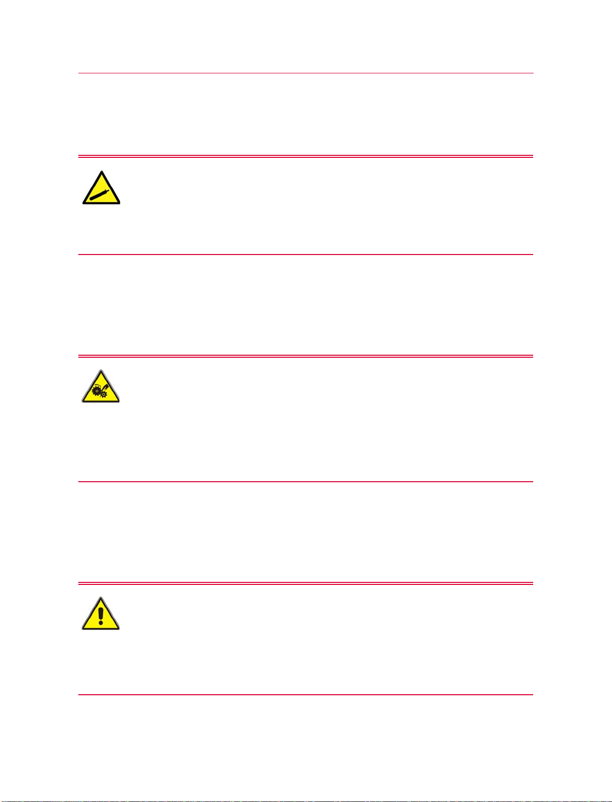
Warning Signs Used
When a symbol is enclosed in a triangle, it becomes a warning sign. A symbol on its own
may be a warning, e.g. the “dangerous voltage” symbol, or may indicate the use of a
control e.g. “Transfer of heat, general” symbol means that the control switches heating
on and off. Chamber controls are shown in the “Function of Controls and Indicators”
chapter.
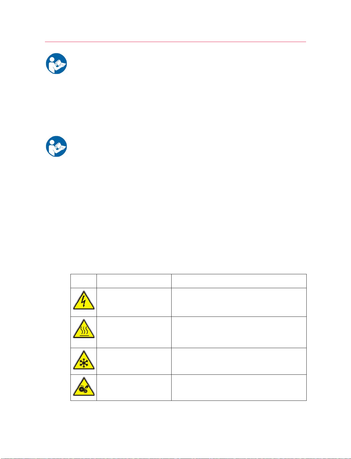
Table 1. Warning Signs
Sign Meaning Standard
Warning - dangerous voltage Symbol derived from BS6217:1981
(417-IEC-5036-a)
“Dangerous voltage”
Warning – hot surface Symbol derived from ISO7000-0535
“Transfer of heat, general”
Warning sign derived from BS 6217:1981
(417-IEC-5041)
Warning – cold surface Symbol derived from
ISO 7000:1989
022 – graphical symbol for use on equipment cooling
Warning – keep fingers away
from rotating machinery
Symbol designed to ISO 3864 - international design
standard for safety symbols.

13
Electrical
Product Support: www.instron.com
Electrical
Warnings
Electrical Hazard – Ensure that the electrical socket used by the chamber power
cable is connected to a suitably grounded point. Disconnect the unit from the power
supply before removing any panel/cover or changing any fuse.
Repairs should only be carried out by an Instron Service Engineer, contact your local
Instron representative if you suspect an electrical fault. Disconnect equipment from the
electrical power supply before removing any electrical safety covers or replacing fuses.
Do not reconnect the power source while the covers are removed. Refit the covers as
soon as possible.
Electrical Disconnection Hazard – After disconnection from the power supply, leave
adequate time for any residual charge to dissipate before touching the conductors
of the power cable attached to the chamber.
When the chamber is disconnected from the mains power supply there may be a
residual charge due to capacitance which gives a risk of electrical shock if the mains
leads are touched. Until this charge has had sufficient time to dissipate, do not touch
the power lead conductors even when the unit is disconnected from the power supply.
Usually the charge dissipates in less than five minutes but the time is strongly
dependent on atmospheric conditions. If in doubt consult a qualified electrician before
disconnecting the unit mains supply.

Chapter: Safety
14 M55-16547-EN
Thermal Contact
Warning
Warning
Take particular care with items that are removed from chambers whilst still hot or cold.
Provide receptacles for such items as they can maintain their temperature for long
periods. When removing items from the chamber use the door as a shield from hot air or
cold cryogenic gases. Cold vapours can cause burns similar to heat burns and provoke
respiratory problems. Depending on the chamber mounting and any attached
accessories, the door may open or close under its own weight (when unlatched).
Specimens
Warning
Hazard - The operator MUST consult their supplier’s Material Safety Data Sheet on the
particular cryogenic gas being used before using this equipment at sub-ambient
temperatures. Instron advise that you receive training in the handling of cryogenic
gases from your supplier.
High/Low Temperature Hazard - Wear adequate personal protective equipment
when using equipment at extremes of temperature. This hazard applies to the
physical parts of the chamber, items in or removed from the chamber and the hot
air/cold cryogenic gases from inside the chamber.
Temperatures above 60°C and below 0°C can cause burns and serious injury. The
chamber has been designed to eliminate possible hazards, but it is inevitable that the
points where specimens or processed items leave the chamber can be at temperatures
outside these limits.
Hazard - Certain materials may become flammable, explosive or toxic when
exposed to extreme temperatures.
The 600 series environmental chambers are not intended for use with unstable
materials that may be flammable, explosive or toxic under extreme conditions. Any
hazard resulting from the failure of a test specimen, assembly, or structure is entirely
the responsibility of the owner and the user of the equipment.
15
Cryogenic Gases: Asphyxiation and Toxicity
Product Support: www.instron.com
Cryogenic Gases: Asphyxiation and Toxicity
Warning
Warning
When cryogenic gases are used with the chamber reduce all spaces around the pullrods
as much as possible, or seal them. Routing the exhaust hose to a well ventilated area
will reduce, but not eliminate, leakage of cryogenic gas around the chamber. Ensure
that the area around the system is suitably ventilated to avoid asphyxiation / toxicity
hazards.
Glass Fibre Insulation
Warning
Asphyxiation Hazard - Cryogenic gases can reduce the amount of oxygen in the
working environment to dangerous levels.
Refer to your supplier’s Material Safety Data Sheet for limits and monitoring information.
Toxicity Hazard - Carbon dioxide is toxic.
In certain concentrations carbon dioxide can be dangerous. Refer to your supplier’s
Material Safety Data Sheet for limits and monitoring information.
Extraction systems may need to meet legislative requirements. Refer to pertinent
government publications for details.
Hazard - Do not disassemble the chamber. Glass fibre insulation can cause skin, eye
or upper respiratory tract irritation in some individuals. Refer to the “Material Safety
Data Sheets” on page 17.
Repairs should only be carried out by an Instron Service Engineer. The glass fibre
insulation used in the chamber is retained within its panels and does not represent a
hazard in normal use. Contact your local Instron representative if any glass fibre
insulation is exposed.
Chapter: Safety
16 M55-16547-EN
High Pressure Gases
Warning
Rotating Parts
Warning
Physical Testing Machine
Warning
High Pressure Gas Hazard - Shutting off a gas cylinder may leave high pressure gas
in pipe work. Always de-pressurise pipe work before disconnection.
Instron advise that you receive training in the handling of high pressure gases from your
gas supplier. Never disconnect high pressure pipe work until you are sure that it is safe
to do so.
Rotating Machinery Hazard - Disconnect power supply before removing the covers.
Repairs should only be carried out by an Instron Service Engineer; contact your local
Instron representative if you suspect a fault with the chamber. There are exposed
rotating parts of the fan in the rear electrical compartment of the chamber. In normal
operation access to the rear compartment is not required. Do not access the rear
electrical compartment without first disconnecting the chamber from the power supply.
Do not reconnect any power supply while the covers are removed.
Moving Parts Hazard - The moving parts of physical testing machines on which
chambers are fitted can give rise to severe moving part hazards.
When using environmental chambers on testing machines the operator must be aware
of all of the moving part hazards and use the environmental chamber taking all
necessary precautions. Consult the safety section of the physical-testing machine
operating instructions.

17
Material Safety Data Sheets
Product Support: www.instron.com
Material Safety Data Sheets
This section contains information to allow you to obtain current Material Safety Data
Sheets (MSDS) directly from the manufacturers. Instron is not responsible for the
content or accuracy of these MSDSs.
Material Location Manufacturer MSDS information
Microtherm
Standard Panel
(Microtherm G).
Microtherm G block is
used in the chamber's
removable wedges on
the 3119-607, 3119-
608 and 3119-610
models only.
Microtherm G block is
contained between the
3119-608 chamber's
outer panels and inner
case.
Belgium
MICROTHERM N V
INDUSTRIEPARK-NOORD 1,
B-9100 SINT-NIKLAAS
Phone : + 32 (0)3 760 19 80
Fax : + 32 (0) 3 760 19 99
Panel MSDS No: msds_G_SG_UK
For the most up to date MSDS for the product
visit the web page
[www.microthermgroup.com].
Sindanyo H91 Sindanyo H91 is used
in the chamber’s
removable wedges on
the 3119-605, 3119-
606 and 3119-609
models only.
Tenmat Limited
Ashburton Road West
Trafford Park, Manchester
M17 1RU
United Kingdom
Phone: +44 (0)161 872 2181
Fax: +44 (0)161 872 7596
e-mail: [email protected]
For the most up to date MSDS Information for
the product visit the web page
[www.tenmat.com].

Chapter: Safety
18 M55-16547-EN
SUPERWOOL 607
Blanket
SUPERWOOL 607
Blanket is contained
between all chamber
outer panels and inner
case.
THERMAL CERAMICS LIMITED
Tebay Road, Bromborough
Wirral, Merseyside CH62 3PH
United Kingdom
Phone: +44 (0) 151 334 4030
Fax: +44 (0) 151 334 1684
THERMAL CERAMICS HSE Department
Route de Lauterbourg - BP 148
67163 WISSEMBOURG Cedex
France
Phone: +33 (0)3 88 54 95 50
Fax: +33 (0)3 88 54 29 20
Blanket MSDS No: 105
Paper MSDS No: 357
To confirm this is the most up to date MSDS
for the product, visit the web page
[www.thermalceramics.com]
SUPERWOOL
Paper 332-E
SUPERWOOL Paper
332-E is contained
within all the chamber
doors.
CO2/LN2Where option is fitted to
your chamber.
Contact your local supplier for information on
material safety.
Material Location Manufacturer MSDS information

19
Product Support: www.instron.com
Chapter 3
Function of Controls and Indicators
•Chamber Door . . . . . . . . . . . . . . . . . . . . . . . . . . . . . . . . . . . . . . . . . . . . . . . . . . . . . 19
•Control Panel Buttons and Indicators . . . . . . . . . . . . . . . . . . . . . . . . . . . . . . . . . . 20
•Rear Input Panel Connections and Labels . . . . . . . . . . . . . . . . . . . . . . . . . . . . . . 22
•Removable Wedges. . . . . . . . . . . . . . . . . . . . . . . . . . . . . . . . . . . . . . . . . . . . . . . . . 24
Chamber Door
Power Indicator
The white LED power indicator is located at the top right hand side of the door. It
illuminates when the circuit breaker is switched on (see “Rear Input Panel
Connections and Labels” on page 22).
Door Handle
The door handle has a two stage operation, i.e. latch and seal. See “Opening and
Closing the Chamber Door” on page 27 for details.
Chapter: Function of Controls and Indicators
20 M55-16547-EN
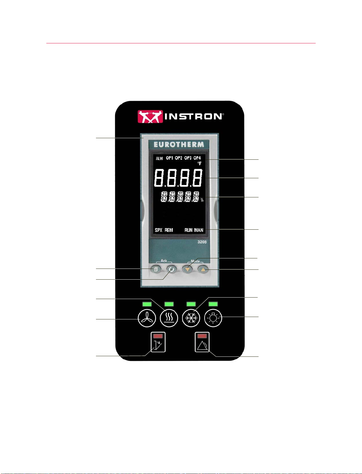
Control Panel Buttons and Indicators
The control panel buttons and indicators are described below.
Figure 2. Control Panel
Eurotherm 3208
Temperature
Controller
Page Button
Heating Button
(Indicator above)
Door Open
Indicator
Up Button
Cooling Button
(Indicator above)
Scroll Button
Down Button
Fan Button
(Indicator above)
Light Button
(Indicator above)
Alarm Tripped
Indicator
Upper Indicators
Upper Display
Lower Display
Lower Indicators
Other manuals for 3119-600 Series
1
Table of contents
Other Instron Industrial Equipment manuals


Popular Industrial Equipment manuals by other brands


Skimz
Skimz FM 100 quick guide

KTR-Group
KTR-Group CLAMPEX KTR 125 Operating & assembly instructions

Mitsubishi Electric
Mitsubishi Electric M800VW Series Connection and set up manual

Petersen
Petersen PeteStop 129 Series instruction manual

Wieland
Wieland SNA 4043K operating instructions

EXPO
EXPO D760-ET MiniPurge manual