ELTRA THERMOSTEP User manual

2009 by ELTRA GmbH Germany – July 2009 – Service Manual Thermostep Page 1
2009 by ELTRA GmbH Germany – July 2009 – Service Manual Thermostep Page 2
NOTE :
This Service Manual serves as a support for service operations at Thermostep analyser of the
company ELTRA. For further questions and support please contact the service technicans of
the manufacturer.
In this Service Manual, no information from the Operation Manual is repeated, however it is
provided as established.
The service should be done only by persons who have mastered the servicing and
maintenance of this device, as well as having further qualifications, especially in the areas of
electronics and physics.
We ask the users of this Service Manual bring to our attention any possible mistakes. We
would also appreciate any suggestions for supplements and improvements to this Service
Manual.
CAUTION !
Before opening this device, always unplug the main power !

2009 by ELTRA GmbH Germany – July 2009 – Service Manual Thermostep Page 3
SERVICEAMANUAL
Thermostep TGA
1. Starting Up
1.1 Installation of Carouseladaptor
1.2 Insertion of Carousel, Speed of lifting up and down, Sensors
1.3 Measurement of grounding conductor resistance
1.4 Measurement of insulating resistance
1.5 Instalation of PC
1.6 Programming of Balance, Adjustment of glass chimney
1.7 Control of voltages
1.8 Measurement of reference temperature
1.9 Regulation of gaspressure, flow
1.10 Purging port
1.11 Internal blower
1.12 Motorsensors
1.13 Calibration of homeposition
1.14 Control of cushioning
1.15 Opening and closing of cover, sensor adjustment
1.16 External blower
2. Malfunctions
2.1 Initialisation test failed
2.2 No rotation of caroussel
2.3 Cover doesn’t close/open
2.4 Balance unstable
2.5 Crucibles/Lids cannot be lowered/lifted
2.6 Junk
2.7 Stage not finished or prolonged
2.8 No Gaspressure, no Oxygen, no Nitrogen
2.9 No communication between PC, Analyser and/or Balance
2.10 Cover opens at 650°C completely
2.11 Cover closes during cooling
3. Service
3.1 External Temperature measurement
3.2 Change of a valve at the manifold
3.3 Change of carousel cylinder
3.4 Change of cover cylinder
3.5 Change of board
3.6 Change of internal blower
3.7 Change of cylinder of internal blower
3.8 Change of balance
3.9 Change of thermocouple
3.10 Change of motor
3.11 Change of power supply

2009 by ELTRA GmbH Germany – July 2009 – Service Manual Thermostep Page 4
3.12 Change of flowmeter, regulator, manometer
3.13 Change of a sensor
3.14 Removal of lower heating element
3.15 Install of lower heating element
3.16 Removal of upper heating element
3.17 Install of upper heating element
4. Miscellaneous
4.1 Diagram of order numbers
4.2 Diagram of wiring
4.3 Diagram of gasflow
4.4 List of Abbreviations/Figures

2009 by ELTRA GmbH Germany – July 2009 – Service Manual Thermostep Page 5
1. Starting up
Please note that first start up of Thermostep-analyser has been done already before delivery of
the instrument. The following described operations are not necessary to be done before the
first analysis.
By reason that a lot of service operations needs a new start up for the according component
and for a better understanding of the working instructions the start up is described here
detailed. For starting of the analyser it is necessary that the computer is connected and that the
software has been started. Please open and remove the lower side panels of the instrument
then removing ground cables. If not mentioned different the components are behind the lower
side panels. It is recommended to read the working instruction once completely and to follow
it step-by-step!
1.1 Installation of Carousel adaptor
Required tools: 2,5 mm Allenkey
The carouseladaptor is located centrally at the lower heating element inside the furnace. It is
necessary for rotation and lifting up and down of the crucible- and lidcarousel. The carousel-
adaptor should be centrally at the notch and horizontally above the lower heating element.
a.) Open the cover of the analyser.
b.) Plug the carouseladaptor through the notch in the lower heating element at the
guidance at the interior of the analyser. (see Fig. 1.1)
Fig. 1.1.: Carouseladaptor – inserted at the lower heating element
2009 by ELTRA GmbH Germany – July 2009 – Service Manual Thermostep Page 6
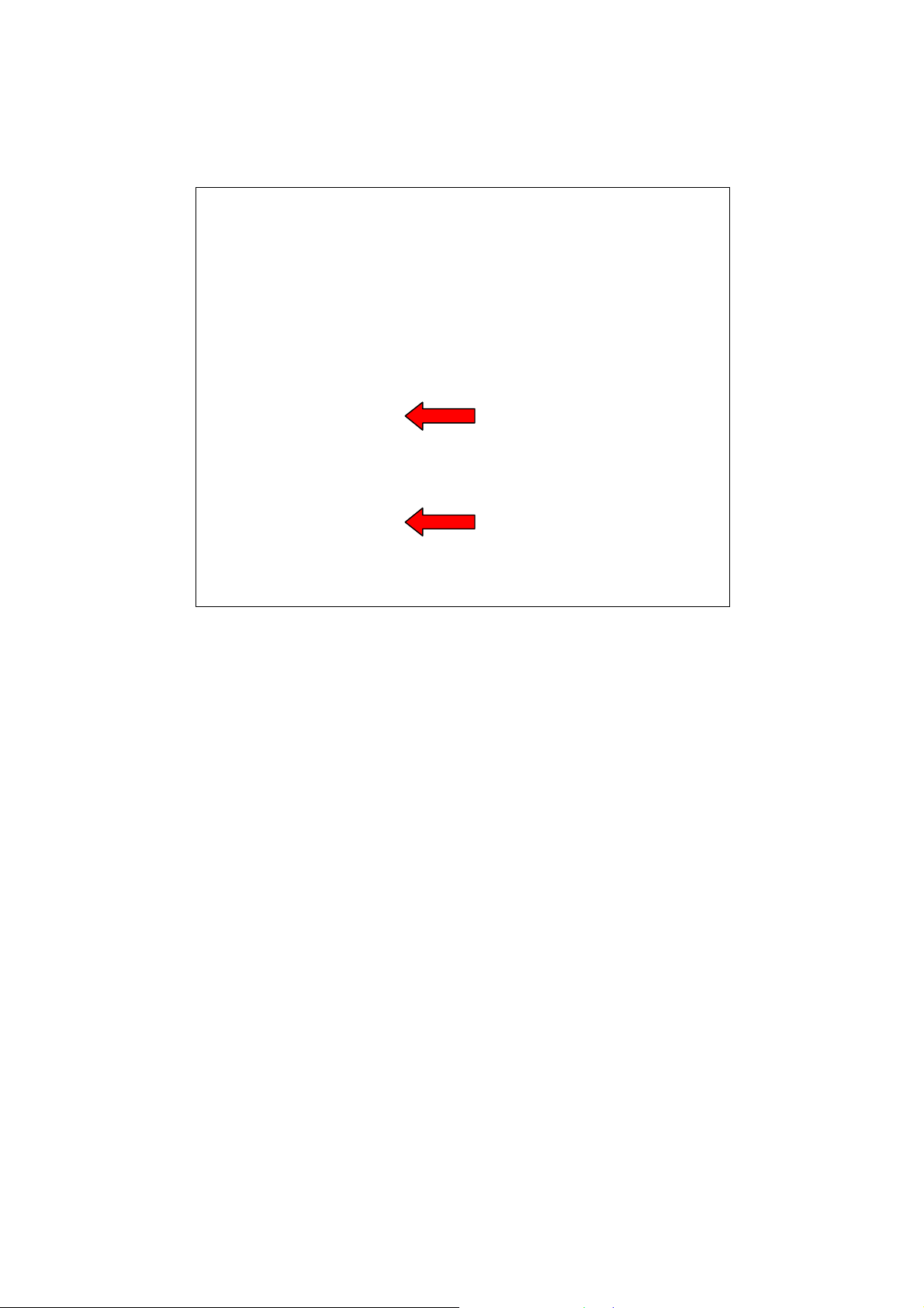
c.) Fasten the carouseladaptor with the 4 x 2,5 mm screws (respectivly 2 screws at 90°
shifted) through the two openings at the guidance (LHS). To fasten the screws
move the carouseladaptor until the screws are visible at the openings (see Fig. 1.2).
Fig. 1.2.: LHS – Guidance of Carouseladaptor (screws marked by red arrows)
If the carouseladaptor not located centrally at the notch of the lower heating element it has to
be adjusted, to avoid it rubbing at the borders of the notch!
Required tools: 2,0 mm Allenkey (angulate)
2,5 mm Allenkey
4,0 mm Allenkey
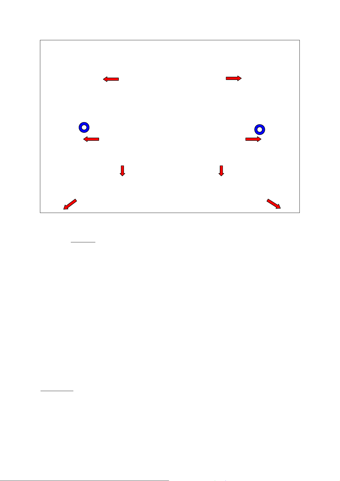
d.) Remove the metal sheet round the lower heating element (inside furnace) by
loosen 6 x 2,0 mm screws (respectivly 3 screws at the left or rather at the right
border of the metal sheet) and 2 x 2,5 mm screws in front of the internal blower
(see Fig. 1.3).
2009 by ELTRA GmbH Germany – July 2009 – Service Manual Thermostep Page 7
Fig. 1.3.: FI – Steel surround of the lower heating element (screws marked by red arrows; blue spots mark
screws below metal sheet)
e.) Unfasten (not loosen completely!) the 2 x 4,0 mm screws below the metal sheet
(see blue spots at Fig. 1.3).
f.) Slide or pitch the carouseladaptor to correct position.
g.) Fasten the 2 x 4,0 mm screws to fix the carouseladaptor at the position.
h.) Fasten the metal sheet again.
1.2 Insertion of Carousel, Speed of lifting up and down, Sensors
Required tools: Screwdriver
The crucible- and the lid-carousel are needed to carry and station the crucibles respectively
and lids during analysis. The lifting up and down of the carousels is controlled by sensors,
that inspect the actual status of the paricular carousel (up or down; see Operationmanual:
Form - Controller).
a.) Put the crucible-caroussell with the openings at the appliance of the carousel-
adaptor.
b.) Lift the carousel up and down and observe the speed of the movement (see
Operation manual: Form – Controller).
Please note: The carousel should be moved as slowly as possible without jerk to keep pedestal
of the balance free of vibration. Vibrations of the pedestal would disturb or prolong the
weighing during analysis, because the balance would need longer time for stabilization. Same
method is essential for lidcarousel.
2009 by ELTRA GmbH Germany – July 2009 – Service Manual Thermostep Page 8
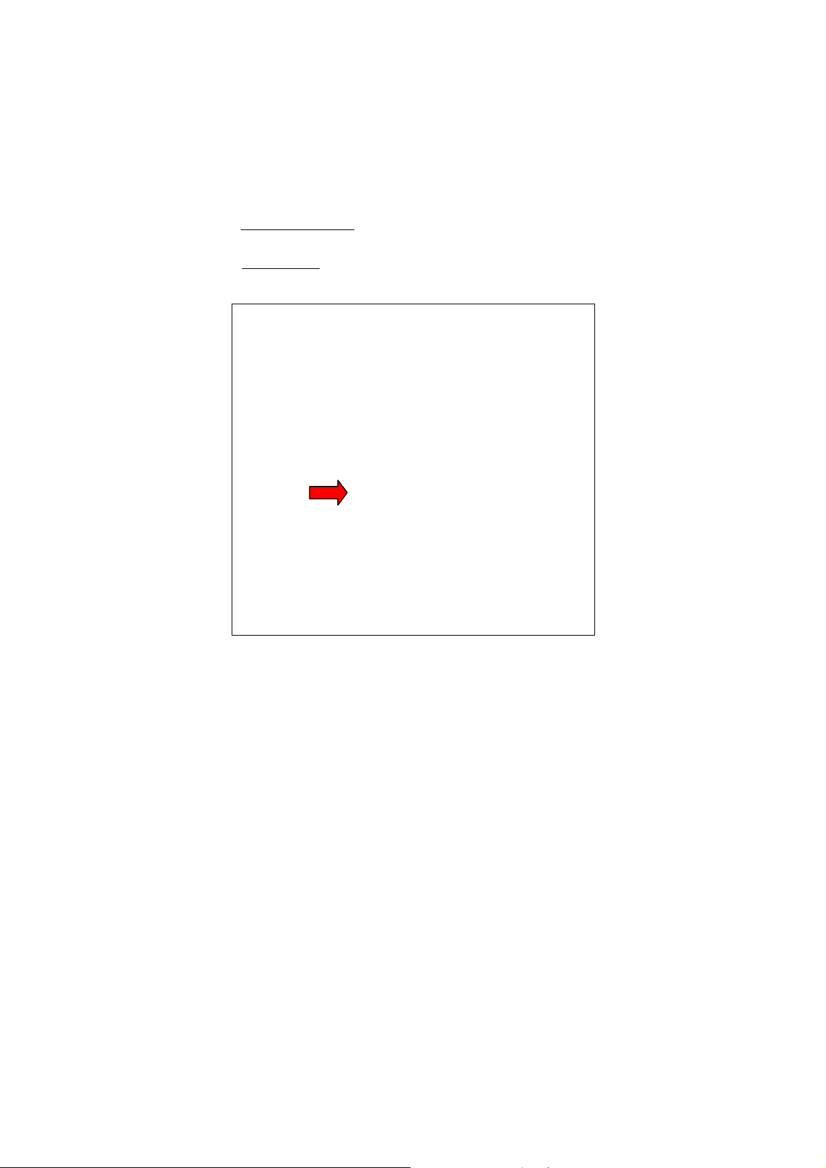
Each carousel is moved by its own cylinder. Every cylinder has a sensor, that sense and report
the actual status of the respective carousel (see Operationmanual: Form – Controller). The
carouselsensors are small black boxes fixed at the cylinder by a screw. For proper working of
the sensors during analysis they should be adjusted at the middle of their working area.
Next to the sensors each cylinder has two chokes, that can be used to regulate the speed of
lifting up or down of the carousels.
The cylinder of the crucible-carousel can be reached from LHS and is located behind the
carouseladaptor. Its sensor is provided at the left side of the cylinder.
The cylinder of the lid-carousel can be reached from the RHS and is located next to the
carouseladaptor. Its sensor is provided at the frontside of the cylinder.
Fig. 1.4: Cylinder of Carousel with sensor (sensor marked by red arrow)
The adjustments for both sensors are analog.
c.) To adjust the sensor open Form Controller at the software TGA. At Inputs the
actual status of the carousel is been shown. Please make sure that the carousel is
lifted up (Inputs:crucibles up marked respectivly Outputs: crucibles down not
marked), by deactivate Outputs: crucibles down if necessary.
d.) Loosen the screw that fixes the sensor at the cylinder until you can move the
sensor.
e.) Slide the sensor slowly upwards until the mark at Inputs:crucibles up disappears.
At the point were the marking disappears the detection area of the sensor ends.
f.) Mark the upper boarder of the detection area.
Please note: If there is no mark visible (Inputs: Crucibles up) before the adjustment of the
sensor it is completely outside of its detection area. In this case move the sensor upwards or
downwards until you see a mark at the software and follow instrution from e.).
g.) Now move the sensor downwards (the mark appears again) until the marking
disappears again. Mark the lower border of the detection area, as well.
h.) Site the sensor nearly at the middle of the detection area and fix the screw again.

2009 by ELTRA GmbH Germany – July 2009 – Service Manual Thermostep Page 9
i.) Control the correct position of the sensor by lifting up and down the caroussell and
check if the status is indicated correctly by the software.
j.) Use the same method for the sensor of the lid-caroussell.
k.) Adjust the speed of the considered caroussell by the particular choke (upper choke:
up; lower choke: down). You reduce speed by closing the choke more and vice
versa.
l.) The setting of the chokes should be fixed by the lock nut.
m.) Control the correct speed after locking again!!!
1.3 Measurement of grounding conductor resistance
For reasons of safety the check of the grounding conductor resistance is done before delivery.
For measurement of the grounding conductor resistance you need an appropriate electric
measuring instrument. Check all metal surfaces of the instrument.
1.4 Measurement of insulating resistance
For reasons of safety the check of the insulating resistance is done before delivery. For
measurement of the insulating resistance you need an appropriate electric measuring
instrument. Follow the instructions of the measuring instrument.
1.5 Installation of PC
The PC is needed for the controlling of the Thermostep-analyser and for coordination of the
analysis. For installation of the PC look at the Operation Manual: Start up.
1.6 Programming of Balance, Adjustment of glass chimney
The balance resides inside the TGA (Display: LHS; cable: RHS). The weighing is done by the
pedestal, that reaches the balance at the interior of the analyser. At the scale plate an
adjustable glass tube is assembled, that should reach up to 5 mm to the underside of the lower
heating element. It is important that the height is adjusted correctly.
a.) The glass tube is build of two parts connected via a ring. To adjust height of the tube
loosen the screw of the ring (LHS) and slide the upper part of the glass tube carefully
upwards.

2009 by ELTRA GmbH Germany – July 2009 – Service Manual Thermostep Page 10
Fig. 1.5: LHS – Glass chimney of the balance (screw of the ring marked by red arrow)
For correct analysis results it is important to avoid rubbing of the balance pedestal at the
borders of the notch at the lower heating element.
b.) To arrange the pedestal at the notch loosen the screw at the upper left edge of the
board and hinge it down (RHS).
c.) At the underside of the balance there are two adjustable feet, that can be turned
simultanously to move the pedestal at the right position.
For the weighing and effective analysis it is necessary to program the balance. For
programming of the balance please read operation manual of the balance. The required
allocations for the use of the balance at Thermostep are:
1.1.4 unstable surroundings
5.1.7 9600 Baud
6.1.3 auto sense stability
1.7 Control of voltages
Required tools: voltage measuring device
These are the different supply voltages of the controller of the analyser. These are shown at
form Status and support the following components:
24 V: supply voltage of the board
18 V: supply voltage of the balance (not measurable)
12 V: supply voltage of the board
2009 by ELTRA GmbH Germany – July 2009 – Service Manual Thermostep Page 11
The voltages were measured with a voltage measuring device at the points TP1 (ground) and
TP2, TP3 respectivly TP4 at the board (see Fig. 1.6). TP2 should show about 24V and TP3
should show about 12 V. TP4 is the supply voltage of the thermocouple and should show
about 5V. (This voltage is not shown at form Status!) This voltage is adjustable at the
potentiometer R9 with a small screw driver.
Fig. 1.6: RHS - Main bord (voltage measuring points marked by red arrow)
1.8 Measurement of reference temperature
Required tools: voltage measuring device
The reference temperature is used as an alignment of the thermocouple and is ascertained via
the adjacent voltage at TP6.
Use the voltage measuring device at TP1 (ground) and TP6 and read the determined voltage.
This voltage equates a temperature, that you can check at the enclosed index and indicates the
proper functionality of the thermocouple.
1.9 Regulation of gaspressure, flow
During an analysis it is possible to create a Nitorgen- or Oxygen-atmosphere at the furnace.
For this the selected gas is fed through feed pipes at the upper heating element. The gas
pressure can be read at the pressure manometer at the frontside of the analyser and should be
about 1,5 bar. The gasflow can be read at the flowmeter and should be about 400 l/h. Before
you start to adjust the gaspressure make sure that the gas bottle pressure of your Nitorgen and
Oxygen is sufficient!
The adjustment of the gaspressure is done by the according pressure controller at the LHS
(Please note: TGAs with two cylinders for lifting the cover have the gaspressure regulators at
the RHS). The front pressure controller regulates the Oxygen- and the rear pressure controller
regulates the Nitrogen pressure.
a.) For examination of the gaspressure activate the particular gas at form “Controller” and
check the pressure at the pressure gauge.
b.) To adjust the gas pressure extract the pressure controller and turn it until the required
pressure is reached.

2009 by ELTRA GmbH Germany – July 2009 – Service Manual Thermostep Page 12
c.) After finishing the adjustment lock the pressure controller back in to avoid an
accidentially alteration of the pressure.
The flow should be controlled simultaneously and is be adjustable by using the inlet needle
valve at the frontside of the analyser. Please note that variation of the flow implicates a
variation of the gaspressure. The adjustment of the flow should be secured by the counter nut
at the choke to avoid accidential alteration of the flow rate.
1.10 Purging ventiles
The exits of the purging pipes are at the upper heating element and are needed to feed in the
particular gas in the furnace during analyis. The gas discharging to the furnace is controlled
by the software. To check the function of the purging switch on the gas flow manually (see
Operator manual: Form - Controller) and check on the basis of the sound and using a suitable
medium if the gas flows through both exits at the furnace.
Fig. 1.7: FI – Purging port at the upper heating element
1.11 Internal blower
The internal blower reduces the cooling down phase after finishing the analysis and is located
at the front inside the furnace. After finishing the analysis it is lifted up automatically at a
temperature of 300° C and closed into its standby position again after reaching room
temperature and finishing cooling down time (see Operation manual: Form - Configuration).
The lifting up and down should occur in a moderate speed. Please note that the cover probably
will be closed after finishing cooling down phase (depending on setting at Form –
Configuration). The closing speed should be fast enough to avoid collision with the cover.
WARNING:The internal blower start automatically after lifting up! RISK OF INJURY!!!
2009 by ELTRA GmbH Germany – July 2009 – Service Manual Thermostep Page 13
a.) Activate the blower at form “Controller” (see Operation manual) to lift it up and check
speed of lifting up and closing.
Fig. .1.8.: FI - Internal Blower (lifted up)
b.) Adjust the speed of lifting up by using the upper choke at the 1. valve of the
valveblock at the LHS.
c.) Adjust the speed of discharging by using the lower choke at the 1. valve of the
valveblock at the LHS.
d.) Lock the adjustment via the counter nuts.
e.) Check speed after locking again as described at a.).
1.12 Motorsensors
Required tools: 8 mm open-end wrench
The analyser uses a stepper motor that is controlled via two sensors, the home sensor and the
move sensor. The homesensor coordinates the rotation of the carousel and the positioning of
the crucibles at the balance pedestal. At this the encoding screw, that is fitted onto the
encoding plate, serves as start- and endpoint of a rotation. During rotation of the encoding-
screw the sensor completes the revolution and starts to incorporate the steps of the new
revolution.
The home sensor (horizontal arrangement) is located at the LHS at reach of the encoding
plate, that rotates simultanously with every carousel revolution and is fixed at the
carouseladaptor. The homeposition is defined by the encodingscrew fitted at the
encodingplate. For recognition of the encoding screw the distance of the homesensor should
be as low as possible. At optimal alignment a sheet of paper (80g) should fit between sensor
and encoding screw. Plese note that the scew has a wide surface area. A collision between
screw and sensor has to be avoided at any time!
The distance and the vertical position of homesensor is adjustable.

2009 by ELTRA GmbH Germany – July 2009 – Service Manual Thermostep Page 14
Fig. 1.9: LHS - Homesensor
a.) Unfasten the nut in front and behind the fitting with the aid of the 8 mm open-end
wrenchs.
b.) Position the encoding screw in front of the sensor.
c.) Aim the sensor at the correct distance to the encoding screw.
d.) Tighten the nut in front of the fitting to fix the distance of the sensor.
e.) Aim the sensor to the correct vertical position (nearly centrally to the encoding screw).
f.) Fasten the nur behind the fitting.
g.) Controll right position of the sensor for a contactless passage with the encoding screw
by moving the encoding plate carefully by hand.
h.) Check correct position and function of sensor by software.
The move sensor controls that an undisturbed rotation can take place, to avoid a damage of
the analyser due to collision.
The movesensor (vertical arrangement) is located to the frontside of the analyser at the guide
bar of the carousseladaptor. It is fixed with two nuts and should be close to the cogwheel
below the encoding plate. To assure an undisturbed revolution the sprockets are registered by
the sensor. It stops the motor if time of recognition is exceeded, to avoid a ripping of the gear
belt or overheating of the motor in case of jam.
The sensor has to be positioned under the spike of the sprockets, so that its possible to
recognize accurately the difference between sprocket and clearance. The distance between
cogwheel and sensor should be as low as possible. The adjusting of the move sensor uses
same procedures the adjusting of the homesensor. To avoid a damage of the sensor, but to
reach an optimal distance to the cogwheel, move the cogwheel after adjusting the sensor by
hand. A complete rotation should take place to be sure that every sprocket is able to pass the
sensor without touching.
2009 by ELTRA GmbH Germany – July 2009 – Service Manual Thermostep Page 15
Fig. 1.10: LHS - Movesensor
1.13 Calibration of homeposition
Required tools: 2,5 mm Allenkey
The correct adjustment of the motorposition assures the optimal siting of the crucibles at the
balance pedestal. The steps that the motor should do after passing the homesensor to siting the
crucible centrally at the pedestal are adjusted here.
For a complete rotation of the caroussel the motor does 32000 steps and the distance between
two crucibles is 1600 steps. The optimal calibration is 800 steps, whereas calibrationvalues
between 600 and 1000 steps are tolerable. The siting of the first crucible directly over the
homesensor is not useful (calibrationvalue <600), because the homesensor do not detect a
single point but an area and the accurate siting of the crucible at the balance would be more
difficult.
a.) Open form “Motor” (see Operation manual).
b.) Click at Read. The saved calibration value is shown (before first starting up: 1). At a
calibration value of 1 the caroussel is positioned over the pedestal between two
crucibles.
c.) Enter 800 as calibration value and confirm it by clicking at Save. You will get a
confirmation that the new calibration value is written to the memory.
d.) Click at Home. Caroussel is rotated to position 20.
e.) Put a crucible at the caroussel and let it move over the pedestal, by entering the
corresponding crucible position at the text box and clicking at Go afterwards.
f.) Lower down the caroussel (see Operation manual: Form – Controller) and check if the
crucible is sited centrally at the pedestal.
g.) If a slight displacement of the crucible at the pedestal it is needed to change the
calibration value. If the crucible is set to far lower the calibration value and vice versa.
h.) Lift up the caroussel again.
i.) Enter the new calibration value and save it like described at c.). Follow the
instructions again.
If correct siting of the crucibles is not possible by using a calibration value between 600
and 1000 it is necessary to adjust the carusseladaptor.

2009 by ELTRA GmbH Germany – July 2009 – Service Manual Thermostep Page 16
j.) Lower the crucible onto the pedestal and check if the crucible is sited to far or not far
enough to decide at which direction the carousseladaptor has to be adjusted.
k.) Do a complete rotation of the caroussel and check by sight at which crucible positions
the screws for fixation of the carousseladaptor a located (LHS). For easier deter-
mination of the positions you can interrupt the rotation by clicking STOP as soon as
the screws become visible and read the crucible position at the screen.
l.) Unfasten the screws via 2,5 mm allen key. (The carousseladaptor is fixed with 4
screws, two pairs shifted at 90°).
m.)Repeat l.) with the second pair of screws.
n.) The carousseladaptor should be now moveable independently from the motorrotation.
Move the caroussel slowly at the needed direction.
o.) Fasten the screws again.
p.) Check the crucibleposition again like described under c.)- d.) and correct via
calibrationvalue when necessary.
1.14 Control of cushioning
The cushioning function is necessary to open the cover of the analyser completely. To reduce
the cooling down phase after analysis, the furnace is opened at a temperature of 650° C 15 cm
wide, before the cover is opened completely at 500° C. At a temperature of 300° C the
internal blower is started to speed up the cooling. After reaching room temperature the
cooling will be continue for the chosen cooling time (see Operation manual: Form –
Configuration: Cooling time) to make sure, that all parts of the furnace are cooled down
completely.
To interrupt the opening of the cover at a certain point and to keep it there, the cushioning
fuction is switched off after passing the backward sensor to avoid the complete opening of the
cover.
a.) To check this function close the cover (see Operation manual: Form – Controller).
b.) Activate function Cover open up at Form Controller and click several times at
Cushioning until cover is opened a gap wide.
c.) Notice if cover stays at the reached position. (A movement of the cover from this
position possibly occurs very slowly and not promptly.)
d.) If cover does not stay at the half opened position close choke at the backside of the 2.
valve at the valveblock (LHS) completely.
e.) Check function again.
1.15 Opening and closing of cover, sensor adjustment
Required tools: 2,5 mm Allen key
Opening and closing of the cover proceeds from many processes automatically. A manual
controlling of this function is possible at Form – Controller. The movement of the cover is
accompanied by an accustic signal and should happen at a moderate speed. The movement is
done by a cylinder that is located at the LHS of the analyser.
(An exeption are instruments that don’t have the opportunity to assemble the exhaust air tube
alternatively at the side. These instruments have two cylinders to open the cover each at every
side. The cylinder at the RHS has two sensors, that control the status of the lid, whereas at the
cylinder at the LHS two chokes control the speed of the movement.)

2009 by ELTRA GmbH Germany – July 2009 – Service Manual Thermostep Page 17
Fig. 1.11: RHS – Sensor of cover
a.) Check if the actual status of the cover is shown at Form – Controller (Inputs)
correctly! (The front sensor register if cover is open, whereas rear sensor registers if
cover is closed!)
b.) Unfasten the screw that fixes the respective sensor (depending on actual status of the
cover) to slide it along the cylinder and push sensor to end of the cylinder out of its
detection area.
c.) Move it along the cylinder (direction: middle of the cylinder) and note on the display
at form Controller! Move the sensor until the acitvation of the respective function
appears to find the border of the detection area.
d.) Mark this border.
e.) Move the sensor further along the cylinder over the detection area until the activation
disappears again to find the other border of the detection area.
f.) Mark this border aswell.
g.) Slide sensor approximately at the middle of the detection area and fix it there by fasten
the screw.
h.) Control the correct position of the sensor through opening and closing the lid. To
control closing of the cover run cushioning function additionally (see 1.14) and pay
attention for activation resp. deactivtion of cover closing. At correct sensor position
the marking disappears and don`t appears again during opening the cover.
Please note that for this adjustement you have to close or to open the cover depending of the
sensor you want to adjust.
i.) Open and close the cover to control the speed of movement!
j.) Regulate the speed via the chokes at the cylinder. The upper choke regulates the
closing speed and the lower choke regulates the opening speed (see Fig. 1.12).
2009 by ELTRA GmbH Germany – July 2009 – Service Manual Thermostep Page 18
Fig. 1.12: RHS – Chokes of cover
k.) Lock your adjustments with the counter nuts.
l.) Check speed after countering again.
1.16 External blower
Required tools: Screwdriver
The external blower is necessary for cooling of Thermostep during analysis and for several of
emerging flue gases.
The exhaust air tube can be assembled at the backside (see Fig. 1.13) or at the interior of the
analyser.
Fig. 1.13: BS – Connector for exhaust air tube

2009 by ELTRA GmbH Germany – July 2009 – Service Manual Thermostep Page 19
From the interior of the instrument the tube is passed through the specified notch at the left
lower side panel (Fig. 1.14).
Fig. 1.14: LHS – Lower side panel with notch for exhausting aur tube
The not used connecting piece is closed with the provided cover cap. The exhaust air tube will
be put on the connecting piece and fixed with the clamp provided. Lead the exhausted air into
an adequate exhaust vent installation.
Plug the dimmer at the socket at the backside of the analyser (see Fig. 1.13). The external
blower starts automatically when it is connected to the dimmer and the Thermostep is
switched on.
Via dimmer you have the opportunity to adapt the power of the external blower. Optimal
setting is approximately half dimmer power. If the chosen power is to low analyser is not
cooled enough during analysis and bad odours emerge. At this case adjust power more.
Too high dimmer power reduces the Oxygen- or Nitrogen purge inside the furnace and results
of analysis varies. Adjust the power lower at this case.

2009 by ELTRA GmbH Germany – July 2009 – Service Manual Thermostep Page 20
2. Malfunctions
If a malfunction occurs during analysis, an error message is shown at Form – Flow
accompanied by a permanent accustic signal. In the following the error message and the error
situation is described followed by a description how to correct it. The troubleshooting is listed
at frequency of its appearance, so it is recommended to check them at the listed sequence.
2.1 Initializationtest failed
After starting software a TGA initialisation test checks functionality of the analyser. For
progress through this test Thermostep has to be switched on (position 1 or 2). The test checks
the single fuctions one after another and interrupts when an error occurs. Depending at which
function the test is interrupted it maybe necessary to open the analyser manually (see
Operation manual: Form – Controller), because the cover doesn’t open until the test is
completed.
The test checks the below functions:
a.) Availability of compressed air
b.) Communication between balance and PC
c.) Functionality of the balance
d.) Communication of Thermostep control unit and PC
e.) Availability of Nitrogen and Oxygen
f.) Functionality of Outputs
At a.)
Error message: “No compressed air!”
Check the availability of compressed air and the gas tube to the analyser!
Fig. 2.1: BS – Connector for compressed air
Table of contents
Other ELTRA Industrial Equipment manuals


