ELTRA CS-800 User manual

© Eltra GmbH, 42781 Haan, Retsch-Allee 1-5, Germany 13.12.2013 0000
Manual
CS-800 Carbon / Sulfur Determinator
Original

2
Copyright
© Copyright by
Eltra GmbH
Haan, Retsch-Allee 1-5
D-42781 Haan
Federal Republic of Germany

3

4
1Notes on the Service Manual ................................................................................................................ 8
2Modification overview ............................................................................................................................ 9
2.1 Up to S/N 0766xxxxxx 9
2.2 From S/N 0767xxxxxx to 0950xxxxxx 13
2.3 From S/N 0951xxxxxx to 1079xxxxxx 15
2.4 From S/N 1080 xxxx to 1556xxxxx 20
2.5 From S/N 1557xxxxxx 25
2.6 new pneumatics (from end 2007) 26
3Fault messages ..................................................................................................................................... 27
3.1 Check base lines 27
3.2 Fluctuating gas flow 28
3.2.1 Blocked metal dust filter 29
3.2.2 Blocked chemicals 29
3.2.3 Blocked paper filters 30
3.2.4 Blocked lance hole over the crucible 30
3.2.5 Blocked furnace outlet 30
3.2.6 Too low oxygen pressure 30
3.2.7 Outlet tap of the oxygen regulator is not properly open 30
3.2.8 Contaminated or corroded solenoid valve 30
3.2.9 Faulty oxygen regulator 30
3.2.10 Bent plastic tube of oxygen supply 30
3.2.11 Heavy item is placed on the plastic tube of the oxygen supply 31
3.2.12 Twisted plastic tube inside the analyzer 31
3.2.13 Oxygen supply is interchanged with the compressed air supply 31
3.2.14 Blocked dust filter cartridge 31
3.2.15Blocked fittings 31
3.2.16 Blocked flow sensor assembly 31
3.2.17 Electronic problem 31
3.3 High carbon results are erratic 32
3.4 No combustion 33
3.4.1 No oxygen pressure 33
3.4.2 No flow 34
3.4.3 Pre-purging 34
3.4.4 Waiting for stability 34
3.4.5 Integration delay 35
3.4.6 Analyzing 35
3.4.7 The command from the microcontroller to start the generator is not received 35
3.4.7.1 Measurements on TP9: 35
3.4.7.2 Checking the generator tube 36
3.4.7.3 If the filament of the generator tube doesn’t glow 37
3.4.7.4 Checking the primary voltage on the high voltage transformer: 38
3.4.7.5 The rectifier could also be faulty 39
3.4.7.6 Loud buzzing sound when the generator turns on 42
3.5 Bad combustion 42
3.6 Electronic- drivers malfunctioning 43
3.7 Furnace does not close 45

5
3.8 Analysis takes too long 46
3.8.1 Additional reasons for excessive analysis duration could be: 47
3.8.1.1 One of the IR-sources is unstable: 47
3.9 Development of dust when closing the furnace 50
3.10 Irregular results 50
3.11 The results are always 0.0000% or 00.0ppm: 51
3.12 Combustion tube - life time is too short 51
3.13 IR-cell temperature control is out of range 53
3.14 Breaker turns off at the beginning of combustion 53
3.14.1 Further causes could be found in the oscillator circuit 55
3.15 Breaker turns off at the end of the analysis 57
3.16 Furnace - large collection of dust when opening 58
3.17 No or low oxygen pressure 59
3.17.1 Possible faults on the front panel of the analyzer 59
3.17.2 On the rear-side of the analyzer: 60
3.17.3 Inside the analyzer: 60
3.17.3.1 Oxygen solenoid valve (V5) may be defective 60
3.17.3.2 Outflow valve does not close 61
3.17.3.3 If the voltage on the outflow valve is constantly at 24 V, then: 61
3.17.4 Other faults 61
3.18 No oxygen flow 61
3.19 Status window message: "Waiting for stability" 61
3.19.1 Reasons for instability: 62
3.19.1.1 Too low deviation value 62
3.19.1.2 Too high noise 62
3.19.1.3 Too high drift 62
3.20 Furnace opens with delay after the end of analysis 62
3.21 Oxygen pressure falls when the furnace opens 64
3.22 Combustion without starting analysis 65
3.23 Crucible cracks or melts 68
3.24 Analysis doesn’t start / no peak on screen 68
3.25 Vibrations on setting 2 68
3.26 Analysis cycle stops before the peak begins 69
3.27 Chopper motor doesn‘t rotate 70
3.28 Sample burns but no peak on the screen 70
3.29 IR signal does not come down to the base line at the end of analysis 70
3.29.1 Too long combustion of a very low carbon sample 71
3.29.2 Copper oxide has a bad quality 72
3.29.3 Path window is not sealed or it is broken 72
3.29.4 Flow stops during analysis 73
4Adjustments, tests and working instructions ................................................................................... 74
4.1 Gas flow controller adjustment and jumper settings 74
4.1.1 Jumper settings 75
4.1.2 Gas flow regulation 76
4.2 Infrared base line adjustments 78
4.2.1 Infrared cell modification - general information 78
4.2.2 General test points 81

6
4.2.2.1 Supply voltages and thermostatic control circuit 81
4.2.2.2 Supply voltages for IR signal processing circuit 81
4.2.3 Test points IR-ranges 83
4.2.3.1 Supply voltages for IR signal processing circuit 83
4.2.3.2 Outputs (base lines about 8VDC. For golden paths adjust 6VDC) 83
4.2.4 Base line adjustments 84
4.2.5 Infrared cell board IRC1.x sections assignment 84
4.2.5.1 Explanations 84
4.2.5.2 Example 84
4.2.6 Voltage of a base line is too high (higher than 9.5V) 85
4.2.6.1 Source voltage – reducing 85
4.2.6.2 Drift too large 86
4.2.7 IR source voltage setting 87
4.2.8 IR cell temperature control 88
4.2.8.1 Examples 88
4.2.8.2 Modifications for higher sensitivity (gain) in the low sulphur range 89
4.2.8.3 IRC board and cross-talk 89
4.3 Pneumatics 90
4.3.1 Pneumatics adjusting for correct furnace movement 92
4.4 Pressure regulation 93
4.5 Purge pressure 94
4.6 Closing cone adjustment 96
4.7 Linearisation 97
4.8 Balance programming 97
4.9 Induction generator control 97
5Service ................................................................................................................................................. 100
5.1 IR-paths, cleaning and replacing 100
5.1.1 Available infrared paths 101
5.2 Infrared electronics 102
5.3 General test points 103
5.3.1 Supply voltages and thermostatic control circuit 103
5.3.2 Supply voltages for IR signal processing circuit 103
5.4 IR-Channels test points 104
5.4.1 Supply voltages for IR signal processing circuit 104
5.4.2 Outputs (base lines about 8VDC. Less no problem) 104
5.5 Infrared power supply 105
5.6 IR-source 106
5.7 Leak checking 108
5.7.1 Furnace inlet system - leaks 111
5.7.1.1 Leaks in the furnace 111
5.7.1.2 Leaks in the furnace outlet system 111
5.7.1.3 Leaks inside the analyzer 111
5.8 Solenoid valves cleaning 112
5.9 Flow sensor - replacing / cleaning 113
5.9.1 Flow sensor replacing 113
5.10 Furnace pneumatics - additional safety features (optional) 114
5.11 Halogen trap - installing 115

7
5.12 Gas saving mode 115
6Miscellaneous ..................................................................................................................................... 117
6.1 Ordering numbers 117
6.1.1 Infrared cells 118
6.1.2 Front side 120
6.1.3 Right side: 122
6.1.4 Pneumatics 124
6.1.5 Oscillating circuit 126
6.1.6 Furnace 128
6.1.7 Furnace cleaning 130
6.2 Wiring (I) 133
6.2.1 UNI 1 143
6.2.2 Gas flow system 144
6.2.3 Valve controlling 146
6.2.3.1 Opening the furnace: 147
6.2.3.2 Closing the furnace: 147
6.3 Spare parts kits 147
6.3.1 Common spare parts kit for all analysers 147
6.3.2 Spare parts kit for CS-800 149
7Maintenance ........................................................................................................................................ 151
8Index .................................................................................................................................................... 152
Appendix .................................................................................................................................. following page

8
Pos: 1. 1 /00 20 Ü bers chr ift en/ 1. Ü bers chr ift en/ 1 Hi nwei se z ur Ser vic e Anl ei tung @ 7\mod_1379492578032_9.docx@ 48845@ 11@ 1
1 0BNotes on the Service Manual
Pos: 1. 2/ 002 5 Warnhi nweis e/G00 02 GEF AHR Le bensg efahr d urch Str omsc hlag - Hoc hspa nnung @ 6\mod_1373271950818_9.docx@ 43119@ 2@ 1
DANGER
G0001
Mortal danger from electric shock
Exposed power contacts - High Voltage
-An electric shock can cause injuries in the form of burns and
cardiac arrhythmia, respiratory arrest or cardiac arrest.
• Disconnect the mains power plug before opening the
analyzer’s cabinet.
Pos: 1. 3 /00 1 0 ELT R A/0 099 St and ard Ka pit el/ Stan dar d M od ul e El tra/ 990 5 M od ul N OT IC E s er vice ma nual (g en eral) @ 7\mod_1379490471353_9.docx@ 48808@ @ 1
NOTICE
In this service manual, no information is repeated from the operation manual, as it
may be appreciated.
Service should only be done by persons who have mastered the servicing and
maintenance of this device, as well as having further qualifications, especially in
the areas of electronics and physics.
We ask the users of this service manual bring to our attention any possible
mistakes. We would also appreciate any suggestions for supplements and
improvements to this service manual.
Pos: 2 / 001 0 ELTR A/------- Sei te num bruc h ----------- @ 6\mod_1368796429449_0.docx@ 41468@ 2 @ 1
9
Pos: 3. 1 /00 20 Ü bers chr ift e n/ELT R A 1. Ü ber schri f ten/ 1 M odi fic ati on over vi ew @ 7\mod_1379493376854_9.docx@ 48867@ 3113333333333333333@1
2 1BModification overview
Pos: 3. 2 /00 1 0 ELT R A/0 015 ser vic e_i nstr uc tio ns /CS-80 0_S er vice /001 0 Änd eru nge n Ü bers ic ht/1 005 Mo dul Änd eru nge n C S-800@ 7\mod_1379493542394_9.docx@ 48878 @ 22222222 @ 1
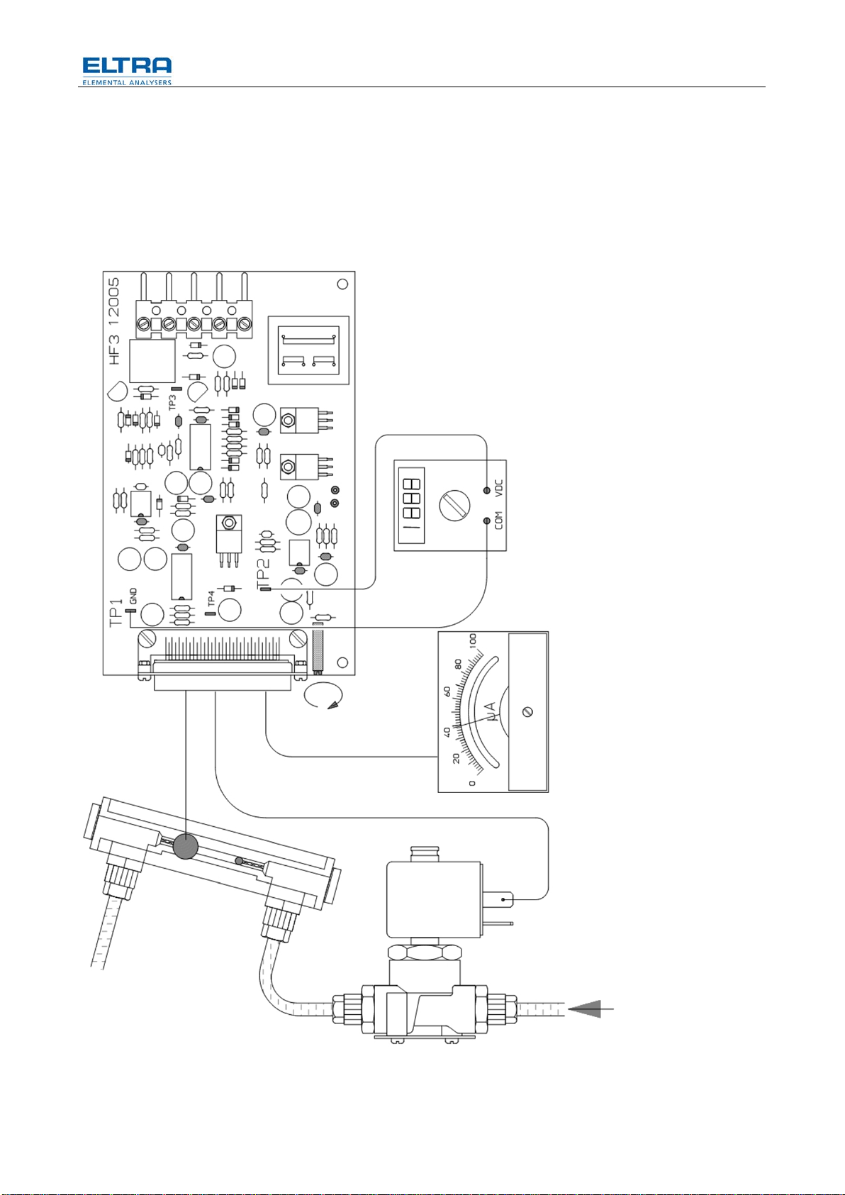
2.1 8BUp to S/N 0766xxxxxx
The CS-800 analyzers are equipped with a flow sensor with optical elements and
with the corresponding board HF-3 and HF-4.
Fig. 1: Draft flow sensor and HF-3
10
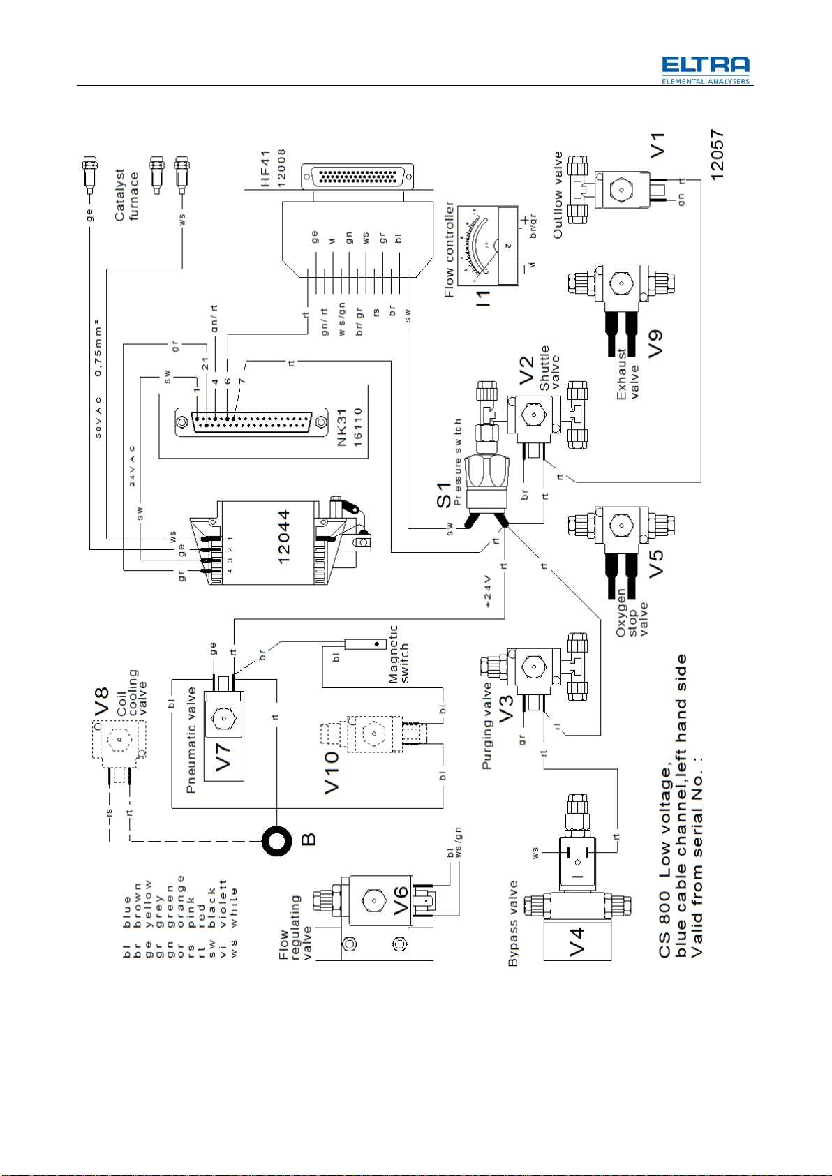
Fig. 2: Draft 12057

11
Fig. 3: Draft 11660
12
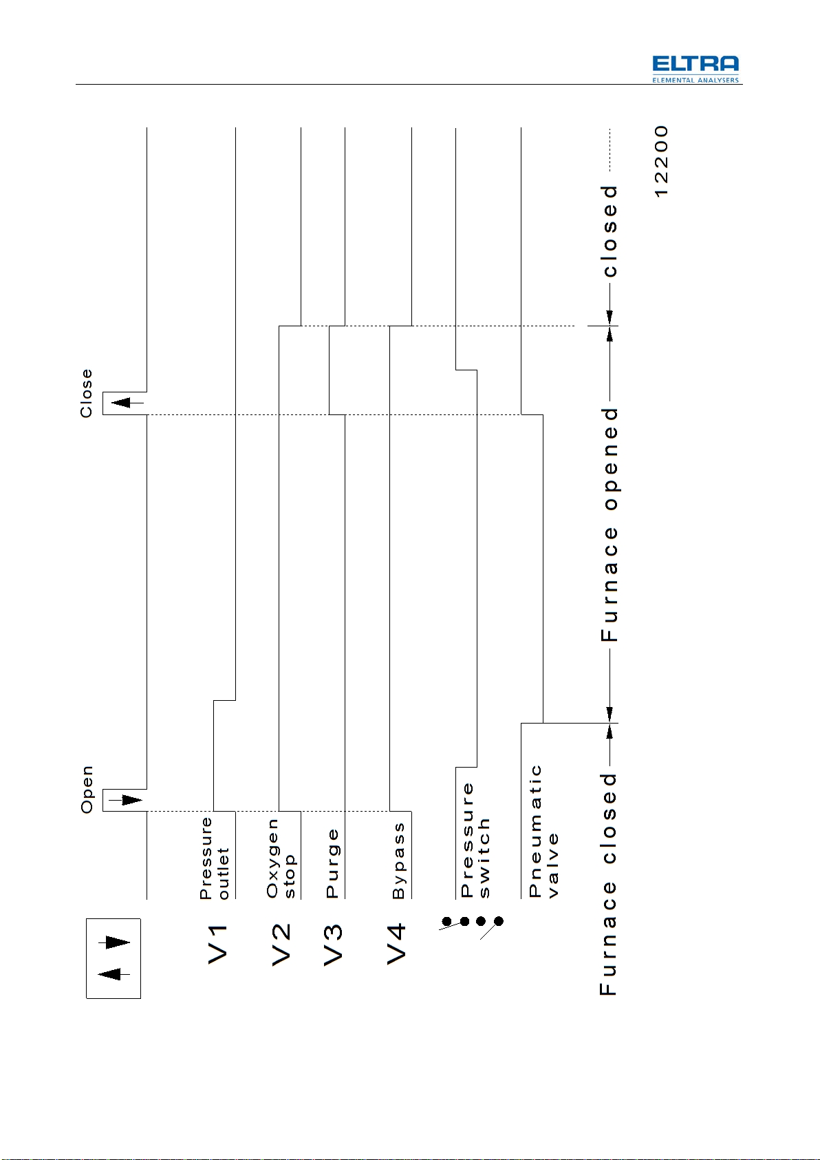
Fig. 4: Draft 12200
13
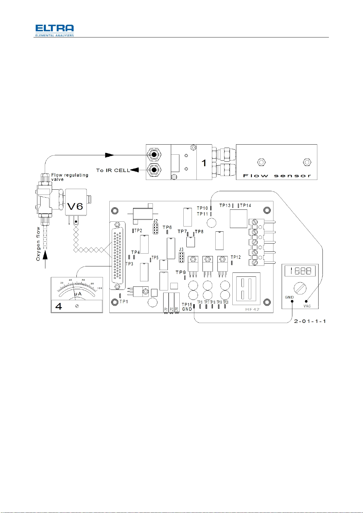
2.2 9BFrom S/N 0767xxxxxx to 0950xxxxxx
The CS-800 is equipped with a flow sensor employing a pressure transducer, and
with the corresponding boards HF-41 and later the HF-42.
These boards also offer:
• Current limit for the induction furnace (on board HF 41/42 adjustment)
• Oxygen flow only during combustion (on board jumper)
• Gas saving mode by controlling the oxygen flow (start / stop) by the software
This function has been included later in the software, from SN / 1080xxxx
Analyzers from SN / 0767 to SN / 1079 can be upgraded with this function.
For description see corresponding service manual.
Fig. 5: Draft 2-01-1-1 (pressure transducer)
14
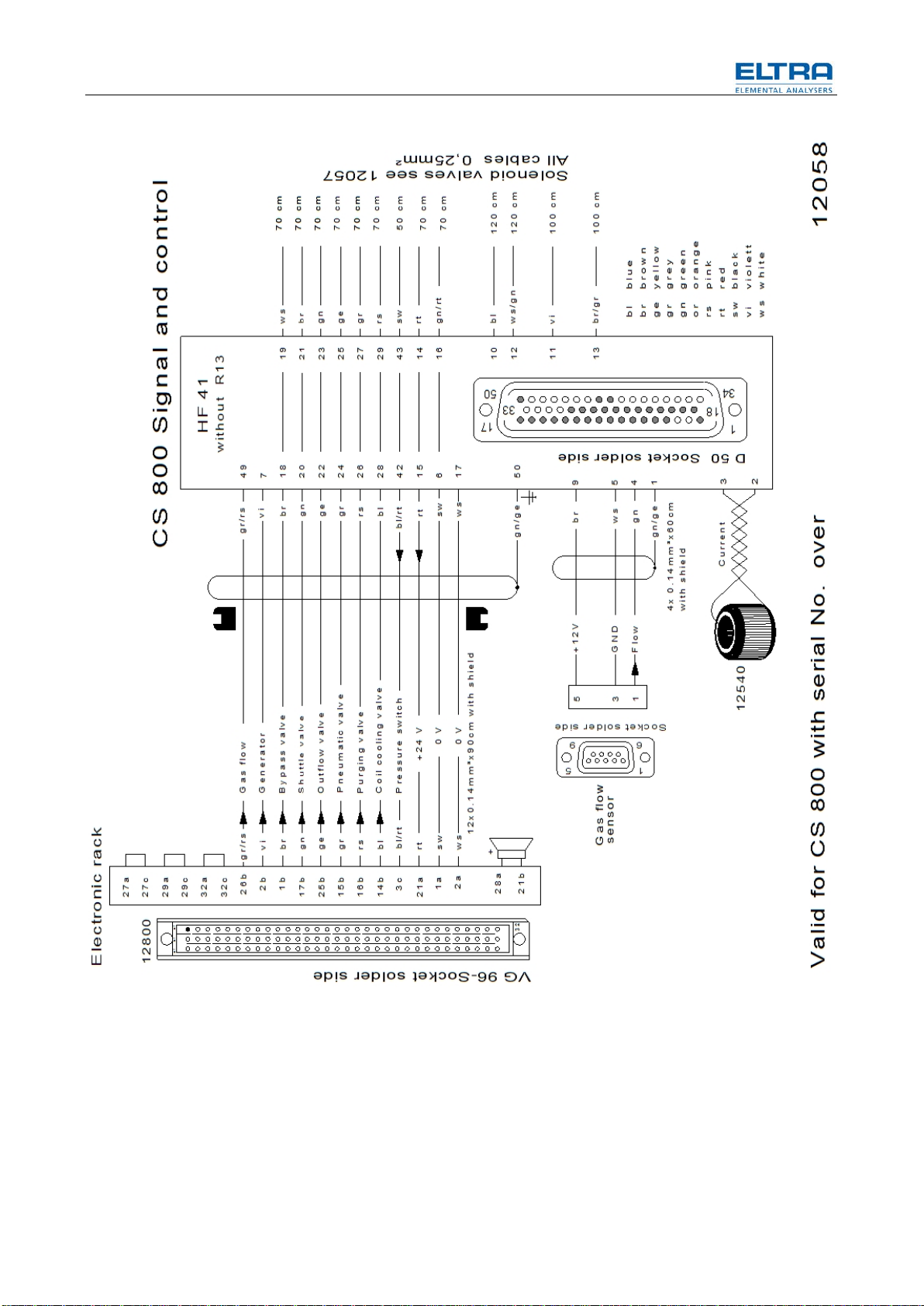
Fig. 6: Draft 12058 (Signal and control)

15
Fig. 7: Draft 11665 (Gas flow diagram)
2.3 10BFrom S/N 0951xxxxxx to 1079xxxxxx
The CS-800 has an additional purging inlet on top of the combustion chamber.

16
• The position of the solenoid valves is rearranged and their controlling
software is modified accordingly. Therefore, a very good care has to be
taken when changing the EPROMS.
• The wiring has also changed. It has been modified to be used with the IR-4,
and the four IR-cell rack. As the 4-cell software was not available, the CS-
800 was equipped with the still available with the 3-range IR-cell using an
adapter and the 3-cell software up to SN / 1079xxxx.

17
Fig. 8: Draft 6-2-4 (Gas flow diagram furnace closed)

18
Fig. 9: Oxygen flow schematically
19
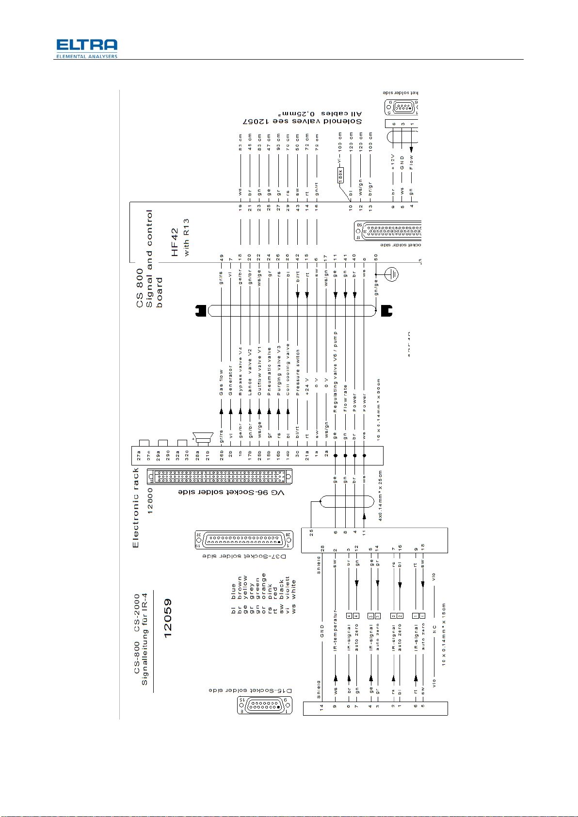
Fig. 10: Draft 12059 (signal and control board)
20
Fig. 11: Draft connector pin assignmen
2.4 11BFrom S/N 1080 xxxx to 1556xxxxx
The CS-800 is equipped with the four IR-cell racks. All electronic boards as well as
the chopper motor are different to those of the previous 3-range IR-cell.
NOTICE
The software version changed to the four IR-ranges!
The gas saving mode is available and selectable in the PC software PLOTCS.
When an analysis has not been carried out for a period of time, the analyzer will
automatically switch to “Gas Conservation Mode“. This effectively means the
carrier gas flow rate is reduced to a minimum, only < allowing a small amount of
oxygen to circulate through the IR-cell etc. The period of time before the Gas
Conservation is activated, can be modified via the PC Software. It is also possible
to have carrier gas flow only during combustion.
Other manuals for CS-800
2
Table of contents
Other ELTRA Industrial Equipment manuals


Popular Industrial Equipment manuals by other brands


HSD
HSD SM 141 D Assembly instructions

SEW-Eurodrive
SEW-Eurodrive DR Series Addendum to the operating instructions

Trotec
Trotec SpeedMarker 300 fiber operating manual

Fröling
Fröling FBR-G2 Installation and operating instructions

Sumitomo Drive Technologies
Sumitomo Drive Technologies Cyclo 6000 Operation and maintenance manual

Bernard
Bernard Intellibus Instructions for use


