EM AAA221 Manual

Break-out Systems
EM Break-out System
AAA221
Installation and Service Manual -
Original instructions
1003658-EMEI-2.0 –Issue 2014-03-20

© All rights in and to this material are the sole property of Entrematic Group AB. Copying, scanning, alterations or modifications are
expressly forbidden without the prior written consent of Entrematic Group AB. Rights reserved for changes without prior notice.
Backtrack information: folder:Workspace Main, version:a109, Date:2014-03-19 time:16:13:49, state: Frozen

CONTENTS
41 Revision .....................................................................................................................................................................................
52 Important information .........................................................................................................................................................
62.1 Intended use ....................................................................................................................................................................................
62.2 Safety precautions .........................................................................................................................................................................
62.3 Electronic equipment reception interference .....................................................................................................................
72.4 Environmental requirements .....................................................................................................................................................
83 Pre-installation ........................................................................................................................................................................
83.1 General tips/Safety concerns .....................................................................................................................................................
94 Installation ................................................................................................................................................................................
94.1 Checking ...........................................................................................................................................................................................
94.2 Installation on door leaves ..........................................................................................................................................................
94.2.1 Fitting the ball catch shoe .........................................................................................................................................
104.2.2 Attachment of the break-out fitting .......................................................................................................................
114.3 Fitting the floor guide ...................................................................................................................................................................
124.4 Fitting the break-out door adaptor .........................................................................................................................................
134.5 Installation of the ball catch .......................................................................................................................................................
144.6 Final adjustment of the ball catch shoe (see also page 9) ................................................................................................
144.7 Fixing the rubber end stops ........................................................................................................................................................
154.8 Fitting the floor guide track ........................................................................................................................................................
164.9 Installation on side screens ........................................................................................................................................................
164.9.1 Fitting the striking plate .............................................................................................................................................
174.10 Fitting the ball catch .....................................................................................................................................................................
184.11 Installation of the intermediate lock for side screens .......................................................................................................
3Issue 2014-03-201003658-EMEI-2.0
CONTENTS

1 Revision
Following pages have been revised:
Revision - →2.0Page
This manual, No. 1003658-EI-1.0, Issue 2014-01-30, replaces earlier version.
1003658-EMEI-2.0Issue 2014-03-204
1 Revision

2 Important information
Instructions for safe operation
•Failure to observe the information in this manual may result in
personal injury or damage to equipment.
•To reduce the risk of injury of persons - use this operator only with
pedestrian doors.
•Do not use the equipment if repair or adjustment is necessary.
•Disconnect supply when cleaning or other maintenance is to be
carried out.
•The operator can be used by children age 8 and above, and persons
with reduced physical, sensory or mental capabilities, or lack of ex-
perience and knowledge, if they have been given supervision or in-
struction by a person responsible for their safety concerning safe
operator use and the possible hazards involved.
This does not however prevent those persons to use the door where
the operator is installed.
•Cleaning and user maintenance shall not be made by children
without supervision.
•Do not let children climb on or play with the door or the fixed/re-
mote controls.
•In all instances, where work is being done, the area is to be secured
from pedestrian traffic, and the power removed to prevent injury.
•The doorset can be operated automatically by sensors or manually
by activators.
5Issue 2014-03-201003658-EMEI-2.0
2 Important information

2.1 Intended use
The EM Break-out System is an automatic sliding door operator developed to facilitate entrances
to buildings and within buildings through sliding doors.
The EM Break-out System is designed to be surface-mounted to the wall or a beam. It is easy to install
for both new construction and retrofit application, and it can be adapted to a wide range of door
requirements. It is to be installed indoors where it is suitable for almost all types of external and
internal sliding doors.
A EM Break-out System operator can be combined with the full range of Entrematic Group safety
units, such as presence and motion sensors.
The door is designed to offer continuous use, a high degree of safety and maximum lifetime. The
system is self-adjusting to the effects caused by normal variations in the weather conditions and
to minor friction changes caused by e.g. dust and dirt.
In emergency situations the doorset is opened and remains open automatically. It may also be
equipped with break-out function, in which case the door leaf is pushed manually open in the escape
direction.
This manual contains the necessary details and instructions for the installation, maintenance and
service of the Sliding Door Operator EM Break-out System.
Save these instructions for future reference.
2.2 Safety precautions
Be sure to complete a risk assessment and site acceptance test before taking the door into operation.
To avoid bodily injury, material damage and malfunction of the product, the instructions contained
in this manual must be strictly observed during installation, adjustment, repairs and service etc.
Training is needed to carry out these tasks safely. Only Entrematic Group-trained technicians should
be allowed to carry out these operations.
2.3 Electronic equipment reception interference
The equipment complies with the European EMC directive (US market FCC Part 15), provided in-
stalled according to Installation and Service manual.
The equipment may generate and use radio frequency energy and if not installed and used properly,
it may cause interference to radio, television reception or other radio frequency type systems.
If other equipment does not fully comply with immunity requirements interference may occur.
There is no guarantee that interference will not occur in a particular installation. If this equipment
does cause interference to radio or television reception, which can be determined by turning the
equipment off and on, the user is encouraged to try to correct the interference by one or more of
the following measures:
•Re-orient the receiving antenna.
•Relocate the receiver with respect to the equipment.
•Move the receiver away from the equipment.
•Plug the receiver into a different outlet so that equipment and receiver are on different branch
circuits.
•Check that protective earth (PE) is connected.
If necessary, the user should consult the dealer or an experienced electronics technician for addi-
tional suggestions.
1003658-EMEI-2.0Issue 2014-03-206
2 Important information

2.4 Environmental requirements
Entrematic Group products are equipped with electronics and may also be equipped with batteries
containing materials which are hazardous to the environment. Disconnect power before removing
electronics and battery and make sure it is disposed of properly according to local regulations (how
and where) as was done with the packaging material.
7Issue 2014-03-201003658-EMEI-2.0
2 Important information

3 Pre-installation
3.1 General tips/Safety concerns
In all instances, where work is being done, the area is to be secured from ped-
estrian traffic, and the power removed to prevent injury.
•If there are sharp edges after drilling the cable outlets, chamfer the edges to avoid damage to
the cables.
•For enhanced security and vandalism protection, always mount the operator access in the in-
terior of a building whenever possible.
•Make sure the ambient temperature is in the range specified in section Technical specification.
•Make sure that the power is off before installing.
•Make sure that the door leaf and the wall are properly reinforced at the installation points.
•Unpack the operator and make sure that all parts are delivered in accordance with the packing
note and that the operator is in good mechanical condition.
•Ensure proper material is being used for the door leaves and that there are no sharp edges.
Projecting parts shall not create any potential hazards. If glass is used bare glass edges shall not
come in contact with other glass. Toughened or laminated glass are suitable glasses.
•Ensure that entrapment between the driven part and the surrounding fixed parts due to the
opening movement of the driven part is avoided. The following distances are considered sufficient
to avoid entrapments for the parts of the body identified;
- for fingers, a distance greater than 25 mm or less than 8 mm
- for heads, a distance greater than
- for feet, a distance greater than 50 mm
- and for the whole body, a distance greater than 500 mm
•The operator may be installed above or below 2.5 m from the floor level.
•The operator shall not be used with a doorset incorporating a wicket door.
1003658-EMEI-2.0Issue 2014-03-208
3 Pre-installation

4 Installation
4.1 Checking
Check that necessary recesses have been cut in the door leaf, side screen and door adaptor and
that the ball catch shoe and the floor guide fit into the door section.
In addition to this instruction, the following drawings are required for a proper installation:
832 273 - Installation drawing, PSB
832 452 - Door leaf for Break-out System, PSB
548 976 - Space required, UniSlide/PSB
832 275 - Ball catch for side screen, PSB
830 555 - Door locking
4.2 Installation on door leaves
4.2.1 Fitting the ball catch shoe
Mount the ball catch shoe into the top rail of the door with the rear head cap Allen screw (slotted
hole). The front screw is to be fitted after final adjustment of the ball catch shoe (see page 13).
1
AAA228
3
2
Ball catch shoe1
Rear head cap Allen screw (M6 x 14)2
Front head cap Allen screw (M6 x 14)3
9Issue 2014-03-201003658-EMEI-2.0
4 Installation
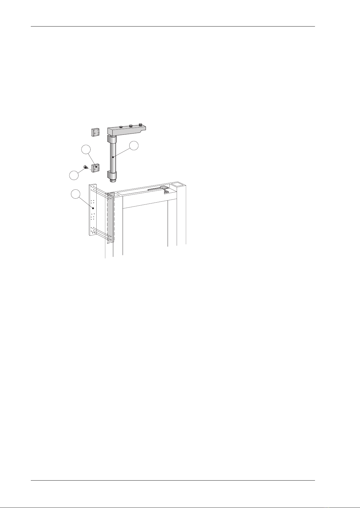
4.2.2 Attachment of the break-out fitting
a Drill attachment holes for the break-out fitting in the door's outer style, using the drill template
provided. Screw clamps assist this operation.
Note! The fixing must be as precise as possible.
b Push the break-out fitting down into the door section and fasten it with 8 countersunk Allen
screws (M6 x 8).
c Use the plastic spacers and longer screws (M6 x 12) if a 4 mm less gap is required between the
fixed screen and the door.
2
AAA227
4
31
Break-out fitting1
Drill template2
Plastic spacer (2 pcs)3
Countersunk Allen screw (8 pcs)4
1003658-EMEI-2.0Issue 2014-03-2010
4 Installation

4.3 Fitting the floor guide
a Set the screw for adjustment of the force exerted on the floor guide track, to approx. 8 mm.
After the fitting, the force can be adjusted by using a screw driver from the underside of the
door leaf.
b Drill and countersink the four holes to fasten the floor guide.
c Push the floor guide into the section and fasten it with 4 countersunk Allen screws (M6 x 8).
If plastic spacers have been used to install the break-out fitting, the same kind of spacers must be
used to install the floor guide. Screws M6 x 12 then have to be used.
To facilitate the installation, push the floor guide foot/shaft to its upper position and fix it with tape.
Adjustment screw (force)1
Floor guide for PSB2
Plastic spacer (2 pcs)3
Countersunk Allen screw (4 pcs)4
Cut-out5
Drill template6
8
5
1
6
3
4
2
11Issue 2014-03-201003658-EMEI-2.0
4 Installation

4.4 Fitting the break-out door adaptor
a Rotate the three tension bolts downwards.
b Keep the break-out fitting together with the anti-sag adjustment device.
c Slip the break-out door adaptor over the break-out fitting until the front edges of the door and
the break-out door adaptor lie edge to edge.
d Tighten the three tension bolts and the bolt on the anti-sag adjustment device.
e Fit the door carriage fittings into the break-out door adaptor and hang the door leaves on the
track of the operator in accordance with the instructions in the manual for the operator con-
cerned.
f Check that the door leaf is parallel with the break-out door adaptor. If not adjust as follows:
g Break out the door leaf.
h Loosen the three tension bolts.
i Compensate for sagging doors by turning the bolt on the anti-sag adjustment device up or
down.
j Tighten the three tension bolts.
AAA220A
1
2
4
3
Tension bolt (3 pcs)1
Anti-sag adjustment device2
Break-out door adaptor3
Break-out fitting4
1003658-EMEI-2.0Issue 2014-03-2012
4 Installation

4.5 Installation of the ball catch
a Unscrew the ball holder from the housing.
b Slide the housing into the opposite end of the break-out door adaptor and fit it opposite the
recess in the door.
c Check that the recess closes over the housing without interference and adjust roughly by estim-
ating the point where the ball will meet the ball catch shoe. Tighten the two countersunk Allen
screws (M6 x 12).
d Screw in the ball holder until the ball is in contact with the slotted hole in the ball catch shoe
and tighten the lock screw.
e The break-out force can be adjusted, if necessary, with the adjustment screw inside the ball
holder. Clockwise turning increases the break-out force.
f Fit the cover plate in the dovetail slot in the ball catch.
1
5
4
2
6
7
AAA223
3
Ball holder1
Housing2
Break-out door adaptor3
Countersunk Allen screw (2 pcs)4
Lock screw5
Cover plate6
Recess in the door7
13Issue 2014-03-201003658-EMEI-2.0
4 Installation

4.6 Final adjustment of the ball catch shoe (see also page 9)
a Adjust the ball catch shoe to the correct position and screw it tight with the rear head cap Allen
screw.
b Mark on the top rail of the door after the round front hole in the shoe.
c Drill, tap and screw the shoe tight with the front head cap Allen screw.
4.7 Fixing the rubber end stops
Fit the brackets and rubber end stops firmly to both ends of the break-out door adaptor.
1
2
AAA224
Rubber end stop1
Bracket2
1003658-EMEI-2.0Issue 2014-03-2014
4 Installation

4.8 Fitting the floor guide track
a Cut the floor guide track (min. = door travel + 75 mm) and fit it on, or into, the floor.
Note! It is important that the floor guide track is fixed absolutely level to prevent derailment
of the floor guide foot when the door is swung out.
b Unfasten the tape holding the floor guide foot/shaft in its upper position.
c Fix the floor guide track so that the floor guide foot/shaft does not leave the track at the end
positions.
dLet the door hang freely, position the guide track accurately and mark its position. It is important
that the slotted countersunk fixing wood screws (1 1/2") are fully screwed in so that they do
not affect the travel of the floor guide foot.
e Swing out the door and check that it functions as required. Ensure that the floor guide foot is
correctly fitted in the guide track, that the door moves freely and that the ball catch operation
is correct.
2
3
L
AAA230
1
1
Floor guide end positions1
Floor guide track2
Side screen3
L = Minimum floor guide track length (Door travel + 75 mm)
15Issue 2014-03-201003658-EMEI-2.0
4 Installation

4.9 Installation on side screens
If required that both the door and side screen shall swing open in a panic situation, the side screen
must be provided with suitable hinges (by other suppliers).
To keep the side screen closed during normal operation, Entrematic Group can supply a snap lock.
Separate drawings show necessary recesses in the door and screen, as well as the installation of
the fittings.
4.9.1 Fitting the striking plate
Fit the striking plate with two head cap Allen screws (M6 x 14) into the side screen in the recess
provided for it.
3
AAA229
1
2
Striking plate1
Side screen2
Door leaf3
1003658-EMEI-2.0Issue 2014-03-2016
4 Installation

4.10 Fitting the ball catch
a Fit the ball catch in the header with two countersunk Allen screws (M6 x 16).
b Adjust as for the ball catch on page 9.
c Fit the cover plate in the dovetail slot on the housing.
3
2
4
1
AAA217
Header1
Housing2
Screw (2 pcs)3
Ball holder4
4
AAA218
1
3
2
Header1
Cover plate2
Side screen3
Door leaf4
17Issue 2014-03-201003658-EMEI-2.0
4 Installation

4.11 Installation of the intermediate lock for side screens
A final adjustment of the depth and height of the door must be made before starting the installation
work. The installation as well as the recess in the side screen for locking brackets are shown on
separate drawings.
a Fix the locking bracket on the back of the door, level with the recess on the side screen.
b Fix the bracket with one screw in the slotted hole, adjust it sideways to the correct position and
tighten the screw.
c Check the break-out, sliding door and intermediate lock functions before the locking bracket
is permanently screwed tight.
d Drill the two remaining holes for the locking bracket and fix the bracket permanently when the
required functions have been achieved.
Recess1
Side screen2
Locking bracket3
Door leaf4
3
4
2
1
AAA225
AAA226
1003658-EMEI-2.0Issue 2014-03-2018
4 Installation


Entrematic Group AB, Lodjursgatan 10, SE-261 44 Landskrona, Sweden
Tel: +46 10 47 48 300 •Fax: +46 418 201 15
Table of contents
Other EM Media Converter manuals

Popular Media Converter manuals by other brands

Calpeda
Calpeda VARIOMAT 2 Series Original operating instructions

Parasound
Parasound D/AC-800 owner's manual

HEIDENHAIN
HEIDENHAIN LS 106 Series Mounting instructions

BaoLai Medical
BaoLai Medical P9-2 instruction manual

Erma Electronic
Erma Electronic AF 9001 instruction manual

Sony
Sony CarrierGate PCWA-DE50 Read this first


