EMAC CPC-2420 User manual

To learn more about EMAC’s products and services and how they can help your project
http://ftp.emacinc.com/Tech_Info/About_EMAC_Products_and_Services.pdf
Authorized Distributor, Integrator, and Value-Added Reseller
Manual downloaded from ftp.emacinc.com
For purchase information please contact info@emacinc.com
For technical support please submit a ticket at www.emacinc.com/support

CPC-2420
2.5” Carrier Board for Mini Biscuit PC
User’s Manual

Copyright notice
This document is copyrighted, 2000, by Advantech Co., Ltd. All
rights are reserved. The original manufacturer reserves the right to
make improvements to the products described in this manual at any
time without notice.
No part of this manual may be reproduced, copied, translated or
transmitted in any form or by any means without the prior written
permission of the original manufacturer. Information provided in this
manual is intended to be accurate and reliable. However, the original
manufacturer assumes no responsibility for its use, nor for any
infringements upon the rights of third parties which may result from
such use.
Acknowledgements
IBM, PC/AT, PS/2 and VGA are trademarks of International Business
Machines Corporation.
Intel and Pentium are trademarks of Intel Corporation.
Microsoft Windows and MS-DOS are registered trademarks of
Microsoft Corp.
C&T is a trademark of Chips and Technologies, Inc.
All other product names or trademarks are properties of their respec-
tive owners.
Part No. 2006242000
1st Edition Printed in Taiwan January 2000

Product warranty
Advantech warrants to you, the original purchaser, that each of its
products will be free from defects in materials and workmanship for
one year from the date of purchase.
This warranty does not apply to any products that have been repaired
or altered by persons other than repair personnel authorized by
Advantech, or which have been subject to misuse, abuse, accident or
improper installation. Advantech assumes no liability under the terms
of this warranty as a consequence of such events.
Because of Advantech high quality-control standards and rigorous
testing, most of our customers never need to use our repair service. If
an Advantech product is defective, it will be repaired or replaced at no
charge during the warranty period. For out-of-warranty repairs, you
will be billed according to the cost of replacement materials, service
time and freight. Please consult your dealer for more details. If you
think you have a defective product, follow these steps:
1. Collect all the information about the problem encountered. (For
example, CPU speed, Advantech products used, other hardware
and software used, etc.) Note anything abnormal and list any on-
screen messages you get when the problem occurs.
2. Call your dealer and describe the problem. Please have your
manual, product, and any helpful information readily available.
3. If your product is diagnosed as defective, obtain an RMA (return
merchandize authorization) number from your dealer. This allows
us to process your return more quickly.
4. Carefully pack the defective product, a fully-completed Repair and
Replacement Order Card and a photocopy proof of purchase date
(such as your sales receipt) in a shippable container. A product
returned without proof of the purchase date is not eligible for
warranty service.
5. Write the RMA number visibly on the outside of the package and
ship it prepaid to your dealer.

Packing list
Before installing your board, make sure that the following materials
have been received:
• 1 CPC-2420 carrier board for CPC-2245 mini biscuit PC
• 1 warranty certificate
• This user's manual
• 1 40-pin FPC cable (part no. 1701400301)
• 1 50-pin FPC cable (part no. 1701500700)
• Y cable (part no. 1700060201)
• HDD cable (part no. 1701440500)
• FDD cable (part no. 1701340600)
• LPT cable (part no. 1703340300)
• COM cable (part no. 1700100250)
• Phoenix power connector (part no. 1652002101)
• Power cable (part no. 1703050050)
If any of these items are missing or damaged, contact your distributor
or sales representative immediately.
Technical support and sales assistance
If you have any technical questions about the CPC-2420 or any other
Advantech products, please visit our support website at:
http://www.advantech.com/support
For more information about Advantech's products and sales informa-
tion, please visit:
http://www.advantech.com

Contents
Chapter 1 Hardware Configuration .............................. 1
1.1 Introduction........................................................................2
1.2 Specifications ......................................................................2
1.3 Safety precautions ..............................................................3
1.4 Jumper settings ..................................................................4
1.4.1 LCD 3.3/5 V select (J6) ..............................................4
1.4.2 Reset (J3) ....................................................................4
1.5 Board layout: dimensions..................................................5
1.6 Installing a Mini Biscuit PC ..............................................7
Chapter 2 Connecting Peripherals .............................. 9
2.1 Board layout: connector locations..................................10
2.2 Floppy drive/parallel port connector (CN2)..................12
2.4 VGA display connector (CN3) ........................................12
2.5 Ethernet configuration (CN4) .........................................13
2.6 Enhanced IDE connector (CN5) .....................................13
2.7 Power connector (CN6/CN15).........................................13
2.8 Keyboard and PS/2 mouse connector (CN7) .................14
2.9 24-bit LCD display connector (CN8)..............................14
2.10 LCD inverter connector (CN9) .......................................14
2.11 Serial ports
(CN10: COM1/RS-232; CN12: COM2/RS-232)............14
2.11.1 RS-232 connection (COM1: CN10) .......................14
2.11.2 RS-232 connection (COM2: CN12) .......................15
2.12 36-bit LCD display connector (CN11)............................15
2.13 ISA connector (J1/J2) ......................................................15

Appendix A Pin Assignments .................................... 17
A.1 Floppy drive/parallel port connector (CN2)..................18
A.2 CRT display connector (CN3).........................................20
A.3 IDE hard drive connector (CN5) ....................................21
A.4 Power connector (CN6) ...................................................22
A.5 Keyboard and mouse connector (CN7)..........................22
A.6 24-bit LCD display connector (CN8)..............................23
A.7 LCD power inverter (CN9) .............................................24
A.8 COM1 RS-232 serial port (CN10) ..................................24
A.9 36-bit LCD display connector (CN11)............................25
A.10 COM2 RS-232 serial port (CN12) ..................................26
A.11 Phoenix power connector (CN15) ...................................26
A.12 ISA-bus FPC connector (J1/J2) ......................................27
A.13 Board layout: locations of Pin 1 of J1 and J2 ................29
A.14 FPC cable layout (J1/J2; 50-pin FPC connector)..........31

Tables
Table 1-1: LCD 3.3/5 V VDD select (J6).......................................................... 4
Table 2-1: Connectors ...................................................................................11
Table 2-2: CPC-2420 serial port default settings...........................................15
Table A-1: Parallel port connector (CN2) ......................................................18
Table A-2: Floppy drive connector (CN2) ......................................................19
Table A-3: CRT display connector (CN3) ......................................................20
Table A-4: IDE hard drive connector (CN5)................................................... 21
Table A-5: Power connector (CN6)................................................................22
Table A-6: Keyboard and mouse connector (CN7) .......................................22
Table A-7: 24-bit LCD display connector (CN8) ............................................23
Table A-8: LCD power inverter (CN9)............................................................ 24
Table A-9: COM1 RS-232 serial port (CN10) ................................................24
Table A-10: 36-bit LCD display connector (CN11) ........................................25
Table A-11: COM2 RS-232 serial port (CN12) ..............................................26
Table A-12: Phoenix power connector (CN15)..............................................26
Table A-13: ISA- bus FPC connector (J1) .....................................................27
Table A-14: ISA-bus FPC connector (J2) ......................................................28
Figures
Figure 1-1: Board layout: dimensions (component side) .................................5
Figure 1-2: Board layout: dimensions (solder side) .........................................6
Figure 1-3: Installation of FPC cable ............................................................... 8
Figure 2-1: Board layout: connector locations (component side) ..................10
Figure 2-2: Board layout: connector locations (solder side) ..........................10
Figure A-1: Board layout: location of Pin 1 of J2 (component side) ..............29
Figure A-2: Board layout: location of Pin 1 of J1 (solder side) ......................30
Figure A-3: FPC cable layout......................................................................... 31

Hardware
Configuration
This chapter gives background informa-
tion on the CPC-2420. It shows you how
to configure the board to match your
application and prepare it for installation
into your PC.
Sections include:
•Introduction
•Specifications
•Safety precautions
•Jumper settings
•Board layout: dimensions
1
CHAPTER

2CPC-2420 User's Manual
1.1 Introduction
The CPC-2420 is a carrier board designed with a SODIMM socket for
connection to a Mini Biscuit PC. It also has connectors for functions
such as VGA, LCD, LAN, FDD, IDE, ISA and a printer port. The
CPC-2420 can help users design their own board easier.
1.2 Specifications
•Two FPC connectors for ISA-bus expansion
•DB-15 VGA connector
•RJ-45 Ethernet connector
•DB-9 COM1 serial port connector
•10-pin COM2 serial port box header
•LCD connector
•One FDD/LPT connector
•44-pin HDD connector
•6-pin PS/2 KB/mouse connector
•Size: 120 x 82 mm
•Weight: 80 g

Chapter 1 Hardware Configuration 3
1.3 Safety precautions
The following sections tell how to make each connection. In most
cases, you will simply need to connect a standard cable. All of the
connector pin assignments are shown in Appendix A.
Warning! Always completely disconnect the power cord from
your PC chassis whenever you are working on it. Do
not make connections while the power is on. Sensi-
tive electronic components can be damaged by a
sudden rush of power. Only experienced electronics
personnel should open the PC chassis.
Caution! Always ground yourself to remove any static charge
before touching any PC board or card. Modern
electronic devices are very sensitive to static electric
charges. Use a grounding wrist strap at all times.
Place all electronic components on a static-dissipa-
tive surface or in a static-shielded bag when they are
not in the PC chassis.

4CPC-2420 User's Manual
1.4 Jumper settings
This section tells how to set the jumpers to configure your board. It
gives the board default configuration and your options for each
jumper. After you set the jumpers and install the board, you will also
need to run your BIOS Setup program to configure the serial port
addresses, floppy/hard disk drive types and system operating parame-
ters. Connections, such as hard disk cables, appear in Chapter 2.
You configure your board to match the needs of your application by
setting jumpers. A jumper is the simplest kind of electric switch. It
consists of two metal pins and a small metal cap (often protected by a
plastic cover) that slides over the pins to connect them. To "close" a
jumper, connect the pins with the cap. To "open" a jumper, remove
the cap. Sometimes a jumper will have three pins, labeled 1, 2 and 3.
In this case, connect either pins 1 and 2 or 2 and 3.
You may find a pair of needle-nose pliers useful for setting the
jumpers.
If you have any doubts about the best hardware configuration for your
application, contact your local distributor or sales representative
before you make any changes.
1.4.1 LCD 3.3/5 V select (J6)
This jumper is used to decide LCD supply voltage.
Table 1-1: LCD 3.3/5 V VDD select (J6)
Function Pins 1-2 Pins 2-3
5 V Closed Open
3.3 V Open Closed
1.4.2 Reset (J3)
Connect a wire from a reset button to J3. To "close" J3 will activate a
reset.
Closed 2 - 3Closed 2 - 3
Closed 2 - 3Closed 2 - 3
Closed 2 - 3
1
3
2
ClosedClosed
ClosedClosed
Closed
OpenOpen
OpenOpen
Open

Chapter 1 Hardware Configuration 5
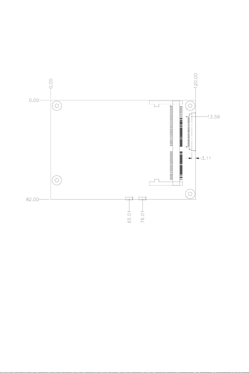
1.5 Board layout: dimensions
Figure 1-1: Board layout: dimensions (component side)
6CPC-2420 User's Manual
Figure 1-2: Board layout: dimensions (solder side)

Chapter 1 Hardware Configuration 7
1.6 Installing a Mini Biscuit PC
Note: The modules can fit into the socket only one way:
the gold pins must point down into the SODIMM
socket.
The procedure for installing a Mini Biscuit PC into the SODIMM
socket of the CPC-2420 appears below. Please follow these steps
carefully.
1. Make sure that all power supplies to the system are switched off.
2. Attach the copper support to the CPC-2420 by fastening the two
thumbscrews.
3. Install the Mini Biscuit PC card (eg. CPC-2245, etc.). Install the
Mini Biscuit PC card so that its gold pins point down into the
SODIMM socket.
4. Slip the Mini Biscuit PC card into the socket at a 45 degree angle,
and carefully push the bottom of the card against the connectors.
5. Gently push the Mini Biscuit PC card into a perpendicular position
until the clips on the ends of the SODIMM socket snap into place.
6. Make sure that the Mini Biscuit PC card is correctly seated, and
that all connectors make contact. The mini Biscuit PC card should
fit snugly in its socket.
7. Pull out the FPC connector. Plug the FPC cable into the FPC
connector, and then push in the FPC connector. (see Fig. 1-3).
Connect the 40-pin FPC cable to J5 of the CPC-2420, and to the
Mini Biscuit PC's FPC connector. The 50-pin FPC cable connects
to J4 of the CPC-2420, and to VGA/LCD module's FPC connector.

8CPC-2420 User's Manual
Figure 1-3: Installation of FPC cable

2
Connecting
Peripherals
This chapter tells how to set up the
CPC-2420's hardware, including connect-
ing peripherals, switches and indicators.
CHAPTER

10 CPC-2420 User's Manual
2.1 Board layout: connector locations
Figure 2-2: Board layout: connector locations (solder side)
Figure 2-1: Board layout: connector locations (component side)

Chapter 2 Connecting Peripherals 11
The following table lists the connectors on the CPC-2420.
Table 2-1: Connectors
Number Function
CN1 SODIMM socket
CN2 FDD/LPT connector
CN3 VGA connector
CN4 Ethernet connector
CN5 IDE connector
CN6 Power connector
CN7 Keyboard and PS/2 mouse connector
CN8 LCD 24-bit connector
CN9 LCD inverter connector
CN10 COM1 RS-232 connector
CN11 LCD 36-bit connector
CN12 COM2 RS-232 connector
CN15 Phoenix power connector
J1 ISA slot connector
J2 ISA slot connector
J4 LCD FPC connector
J5 VGA/COM/KB/MS FPC connector

12 CPC-2420 User's Manual
2.2 Floppy drive/parallel port connector
(CN2)
You can attach up to two floppy disk drives to the CPC-2420's
onboard connector. You can use any combination of 5.25" (360 KB /
1.2 MB) and/or 3.5" (720 KB / 1.44 / 2.88 MB) drives.
The board comes with a 34-pin daisy-chain drive connector cable.
One end of the cable has a 34-pin flat-cable connector. The other end
has two sets of floppy disk drive connectors. Each set consists of a
34-pin flat-cable connector (usually used for 3.5" drives) and a
printed-circuit-board connector (usually used for 5.25" drives). You
can use only one connector in each set. The set on the end (after the
twist in the cable) connects to the A: floppy. The set in the middle
connects to the B: floppy.
The parallel port is normally used to connect the CPU card to a
printer. The CPC-2420 has a parallel port cable, accessed via connec-
tor CN2. The parallel port is designated as LPT1, and can be disabled.
Note that an FDD cannot operate simultaneously with the parallel
port.
2.4 VGA display connector (CN3)
The CPC-2420 provides a VGA controller for a high resolution VGA
interface. The CPC-2420's CN3 is a DB-15 connector for VGA
monitor input. Pin assignments for the CRT display are detailed in
Appendix A.
Note that the VGA connector only operates when Advantech's
CPC-2520 is not present in the system.
Table of contents
Other EMAC Carrier Board manuals


