eMachines D845GVSR User manual

User’s Guide
D845GVSR Motherboard
CCOONNTTEENNTTSS
Chapter 1 Motherboard Description
Motherboard Overview 1-3
Chapter 2 Using the BIOS Setup Program
About the Setup Program 2-1
Entering the Setup Program 2-2
BIOS Setup Program 2-4
Chapter 3 Installing Board Options
Before You Begin 3-1
Installing and Removing the Processor 3-2
Installing and Removing Memor Modules 3-5
Changing the Jumpers 3-7
Replacing the Batter 3-8
The Things to do in Post-installation 3-9
Appendi A Specifications
Specifications A-1
Rev. A


i
Battery Warning Instruction
Caution
If battery is incorrectly replaced there poses a danger of explosion. Replace battery only with the same or
equivalent type recommended by the manufacturer. Discard used batteries according to the manufacturer’s
instructions.
Attention
Il y a danger d‘explosion s‘il y a remplacement incorrect de la batterie. Remplacer uniquement avec une
batterie du méme type ou d‘un type recommandé par le constructeur. ettre au rébut les batteries usagées
conformément aux instructions du fabricant.
Vorsicht
Explosionsgefahr bei unsachgemäß em Austausch der Batterie. Ersatz nur durch denselben oder einen vom
Hersteller empfohlenen ähnlichen Typ. Entsorgung gebraushter Batterien nach Angaben des Herstellers.
Fuse Warning Instruction
Caution
For continued protection against risk of fire, replace only with same type and rating of fuse. Disconnect input
power before servicing. Only connect this equipment to an earthed socket outlet.
Vorsicht
Vor jeder service-arbeit netzstecker ziehen! Apparatet ma kun tilkobles jordet stikkontakt.
Attention
Debrancher avant d’ouvrir. Apparaten skall anslutas till jordat nätuttag.
Atencion
Desconecte fuerza electrica antes del servicio. Laite on liitettävä suojäkosketinistoraasian.
Safety Information

ii
The information in this user’s guide is subject to change without notice.
e achines, Inc. shall not be liable for technical or editorial errors or omissions contained herein; nor for
incidental or consequential damages resulting from the furnishing, performance, or use of this material.
e achines, stylized “e” and figure logo are either trademarks or registered trademarks of e achines, Inc.
in the United States and/or other countries.
All other product and brand names are trademarks of their respective owners.
©2003 e achines, Inc. All rights reserved.
Before You Read
NOTE
Depending on the model, our computer’s components ma var and look slightl different than those
pictured.

iii
CONTENTS
Chapter 1 Motherboard Description
otherboard Overview............................................................................................ 1-3
Rear Panel Connectors ..................................................................................... 1-4
Chapter 2 Using the BIOS Setup Program
About the Setup Program ........................................................................................ 2-1
Entering the Setup Program .................................................................................... 2-2
Help Window ................................................................................................... 2-3
BIOS Setup Program ............................................................................................... 2-4
ain enu ....................................................................................................... 2-4
Advanced enu ............................................................................................... 2-5
Security enu .................................................................................................. 2-8
Power enu ..................................................................................................... 2-10
Boot enu ........................................................................................................2-10
Exit enu .........................................................................................................2-12

iv
Motherboard Description
Chapter 3 Installing Board Options
Before You Begin ................................................................................................... 3-1
Installing and Removing the Processor .................................................................. 3-2
Installing the Processor .................................................................................... 3-2
Removing the Processor .................................................................................. 3-4
Installing and Removing emory odules ........................................................... 3-5
Installing a emory odule ........................................................................... 3-6
Removing a emory odule ......................................................................... 3-6
Changing the Jumpers ............................................................................................ 3-7
Replacing the Battery ............................................................................................. 3-8
The Things to do in Post-installation ..................................................................... 3-9
Appendix A Specifications
Specifications ........................................................................................................ A-1

1-1
Motherboard Description
Motherboard Description
Motherboard Description
This chapter describes the major features of your motherboard.
Your motherboard offers the following features:
● icro ATX form factor
● Intel®Pentium®4 processor in the mPGA 478 pin package
● Two DI sockets, expandable up to 2 GB using 1 GB DDR SDRA modules
● Two built-in Enhanced IDE controllers
● Intel®82845GV Graphics emory Controller Hub (G CH)
● Intel®82801DB I/O Controller Hub (ICH4)
● Built-in high performance audio CODEC and PCI audio controller in Intel ®82845GV G CH
● NSC PC87372 super I/O controller
● Intel®82562ET 10/100 bps (PLC) device
● Advanced Power anagement (AP ) and Advanced Configuration and Power Interface
(ACPI)
● Three 32-bit PCI expansion card connectors
● System BIOS and video BIOS shadow RA
● Plug-and-Play (PnP) BIOS feature
● Password function by using BIOS
● Video memory using main memory

1-2
Motherboard Description
● Two PS/2 style connectors for keyboard and mouse
● One video connector
● Four USB 2.0 connectors and one pinheader that supports two USB connectors
● One LAN connector
● One serial port connector
● One parallel port connector
● Three audio jacks
NOTE
The internal graphics device on Intel 82845GV supports Intel D namic Video Memor
Technolog (D.V.M.T). D.V.M.T. d namicall responds to application requirements b
allocating the proper amount of displa and texturing memor .
As our s stem has sharing memor architecture using the main memor for video memor ,
the usable main memor size is less than real size when the computer is running.
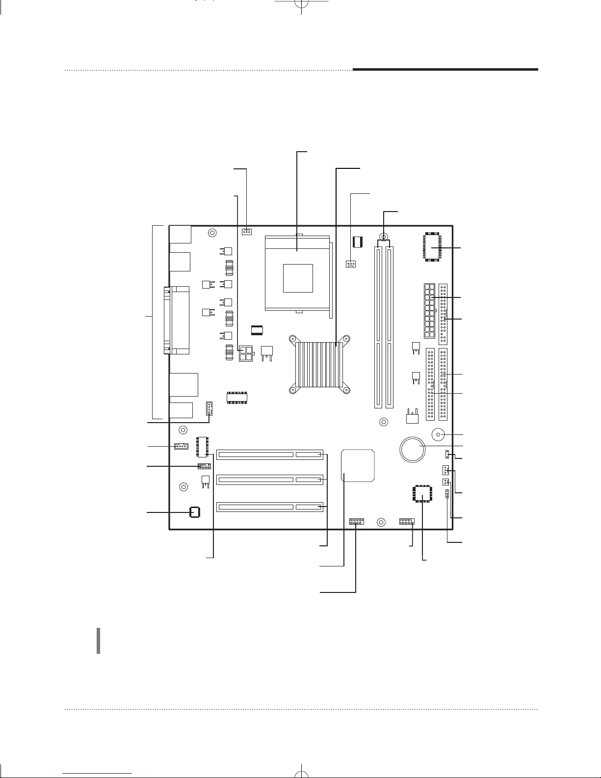
CPU fan connector
PCI slots
Back panel
I/O connectors
Battery
Speaker
Realtek ALC202A
audio codec
Intel 82562ET
10/100 Mbps (PLC) device
Power supply
connector
Secondary EIDE
connector
Primary EIDE
connector
NSC PC87372
super I/O controller
FDD connector
Auxiliary 12V power
supply connector
mPGA478 socket
Rear chassis fan connector
DIMM sockets
Intel 82845GV Graphics Memory
Controller Hub(GMCH)
Front panel
audio connector
CD audio connector
Video audio connector
Front panel
USB connector
Intel 82801DB I/O
controller Hub (ICH4)
Front Chassis
fan connector
Chassis intrusion
connector
Jumper
Auxiliary front
panel power
LED connector
FWH
(Firmware Hub)
Front panel
connector
1-3
Motherboard Description
NOTE
The motherboard's components ma var and look slightl different.
Motherboard Overview
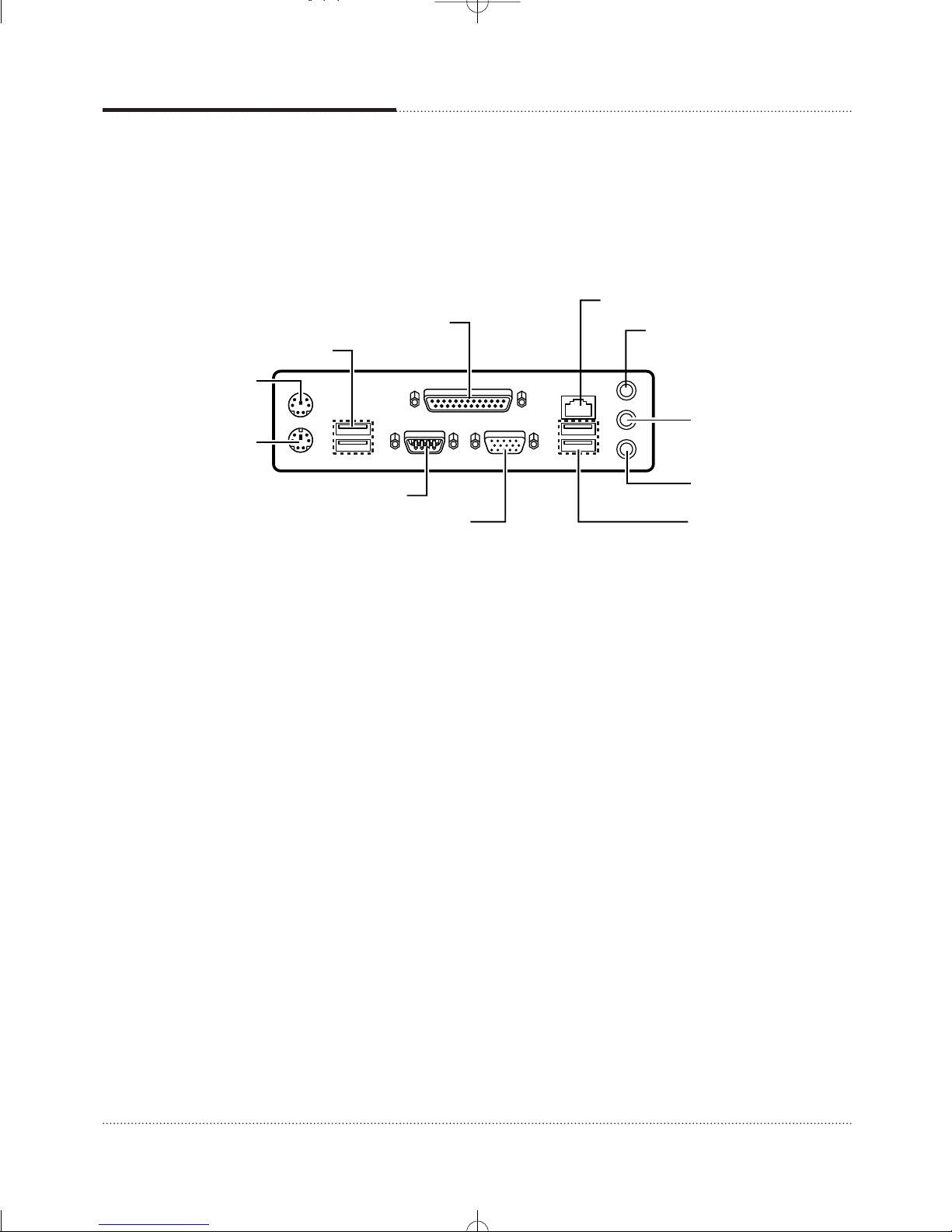
Serial port (COM1) connector
PS/2 mouse
connector
PS/2 keyboard
connector
USB connectors
Parallel port connector
Microphone jack
Line-in jack
Line-out jack
LAN connector
Video connector
USB connectors
1-4
Motherboard Description
Rear Panel Connectors
The motherboard has connectors for peripheral devices.

2-1
Using the BIOS Setup Program
Using the BIOS Setup Program
Using the BIOS Setup Program
This chapter explains how to use the BIOS Setup program. You can use the Setup program to
change the computer’s configuration information and boot-up sequence, etc.
Your system uses a Phoenix BIOS, which is stored in flash memory on the motherboard. This
enables you to run the program at any time when you turn on or reset your computer.
The configuration you define through the Setup program is stored in a special area of memory
called C OS RA . The battery on the motherboard backs up this memory, so the memory is not
erased when you turn off or reset the computer. Whenever you reboot the computer, it checks the
settings, and if it discovers a difference between the information in the C OS RA and its actual
hardware configuration, it prompts you to run the Setup program.
About the Setup Program

2-2
Using the BIOS Setup Program
To enter the Setup program, turn the computer on and press DEL as soon as you see the
“emachines” logo.
If you do not press the key quickly, the computer starts loading the operating system.
When you enter the Setup program, you will see the Setup menu. The legend bar at the bottom of
the menu displays function keys used in Setup.
The Setup program is for viewing and changing the BIOS settings for a computer. Setup is
accessed by pressing the <DEL> key after the Power-On Self Test (POST) begins and before the
operating system boot begins.
The next table shows the menus available from the menu bar at the top of the Setup screen.
Entering the Setup Program
NOTE
For reference purposes, write down the current Setup settings. When ou make changes to the
settings, update this record.
NOTE
The actual menus displa ed on our s stem ma differ depending on the hardware and features
installed in our computer.
Setup Menu Screen Description
Main Allocates resources for hardware components.
Advanced Specifies advanced features available through the chipset.
Security Specifies passwords and security features.
Power Specifies power management features.
Boot Specifies boot options and power supply controls.
Exit Saves or discards changes to the Setup program options.

2-3
Using the BIOS Setup Program
The next table shows the function keys available for menu screens.
Help Window
The field help window on the right of each menu displays the help text for the currently selected
field. Also, if pressing <F1> on any menu, you will see the General Help.
Setup Key Description
<F1> or <Alt-H> Brings up a help screen for the current item.
<Esc> Exits the menu.
<> or <> Selects a different menu screen.
<> or <> Moves cursor up or down.
<Home> or <End> Moves cursor to top or bottom of current menu.
<PgUp> or <PgDn> Moves cursor to previous or next page on scrollable menu.
<F5> or <-> Selects the previous value for a field.
<F6> or <+> or <Space> Selects the next value for a field.
<F9> Load the default configuration values for the current menu.
<F10> Save the current values and exit Setup.
<Enter> Executes command or selects the submenu.

2-4
Using the BIOS Setup Program
BIOS Setup Program
Main Menu
This menu reports processor and memory information and is for configuring the system date,
system time, floppy options, and IDE devices.
Feature Options Description
BIOS Revision No options Displays the BIOS revision.
Processor Type No options Displays processor type.
Processor Speed No options Displays processor Speed.
System Bus Speed No options Displays tne system bus speed.
System Memory No options Displays the system memory speed.
Speed
Cache RAM No options Displays the size of second-level cache.
Total Memory No options Displays the total amount of RAM.
Memory Bank 0 No options Displays the memory specification installed in Memory Bank 0.
Memory Bank 1 No options Displays the memory specification installed in Memory Bank 1.
System Time Hour, minute, and Specifies the current time.
second
System Date Month, day, and year Specifies the current date.
2-5
Using the BIOS Setup Program
Advanced Menu
This menu is for setting advanced features that are available through the chipset.
Feature Options Description
Boot Configuration No options Configures Plug and Play. When selected, displays the Boot
Configuration submenu.
Peripheral Configuration
No options Configures peripheral ports and devices. When selected, displays the
Peripheral Configuration submenu.
IDE Configuration No options Specifies type of connected IDE devices. When selected, displays
the IDE Configuration submenu.
Diskette Configuration
No options Configures the diskette drive. When selected, displays the Diskette
Configuration submenu.
Video Configuration No options Configures video features. When selected, displays the Video
Configuration submenu.
USB Configuration No options Configures USB support. When selected, displays the USB
Configuration submenu.
Feature Options Description
Plug & Play O/S • No Specifies if manual configuration is desired. No lets the BIOS configure all
• Yes devices. This setting is appropriate when using a Plug and Play operating
system. Yes lets the operating system configure Plug and Play devices
not required to boot the system. This option is available for use during lab
testing.
Boot Configuration Submenu
This submenu is for configuring Plug and Play.

2-6
Using the BIOS Setup Program
Feature Options Description
Serial Port A • Disabled Configures serial port A.
• Enabled Auto assigns the first free COM port, normally COM1, the address 3F8h,
• Auto and the interrupt IRQ4. An * (asterisk) displayed next to an address
indicates a conflict with another device.
Parallel Port • Disabled Configures the parallel port.
• Enabled Auto assigns LPT1 the address 378h and the interrupt IRQ7. An * (asterisk)
• Auto displayed next to an address indicates a conflict with another device.
Mode • Output only Selects the mode for the parallel port. Not available if the parallel port is
• Bi-directional disabled.
• EPP Output Only operates in AT†-compatible mode. Bi-directional operates
• ECP in PS/2-compatible mode. EPP is Extended Parallel Port mode, a high-
speed bi-directional mode. ECP is Enhanced Capabilities Port mode, a
high-speed bidirectional mode.
Audio Device • Disabled Enables or disables the onboard audio subsystem. For boards with no
• Enabled onboard audio subsystem, this option does not appear.
LAN Device • Disabled Enables or disables the onboard LAN device. For boards with no
• Enabled onboard LAN subsystem, this option will not appear.
Peripheral Configuration Submenu
This submenu is for configuring peripheral ports and devices.
Feature Options Description
IDE Controller • Disabled Specifies the integrated IDE controller.
• Primary Primary enables only the primary IDE controller. Secondary enables only
• Secondary the secondary IDE controller. Both enables both IDE controllers.
• Both
Primary IDE Master No options Reports type of connected IDE device. When selected, displays the
Primary IDE Master submenu.
Primary IDE Slave No options Reports type of connected IDE device. When selected, displays the
Primary IDE Slave submenu.
Secondary No options Reports type of connected IDE device. When selected, displays the
IDE Master Secondary IDE Master submenu.
Secondary No options Reports type of connected IDE device. When selected, displays the
IDE Slave Secondary IDE Slave submenu.
IDE Configuration Submenu
This submenu is for configuring IDE devices.

2-7
Using the BIOS Setup Program
Feature Options Description
Drive Installed No options Displays the type of drive installed.
Type • Auto Specifies the IDE configuration mode for IDE devices. User allows
• User capabilities to be changed. Auto fills-in capabilities from ATA/ATAPI
device. Maximum Capacity No options Displays the capacity of the
drive.
Maximum Capacity
No options Displays the capacity of the drive.
LBA/Mode • Disabled Selects the translation mode for the IDE hard disk. (This item is read-only
• Auto unless Type is set to User.)
Block Mode • Disabled Disabled = Data transfers to/from the device occur one sector at a time.
• Auto Auto = Data transfers to/from the device occur multiple sectors at a time
if the device supports block mode transfers. (This item is read-only unless
Type is set to User.)
PIO Mode • Auto Specifies the PIO mode. (This item is read-only unless Type is set to User.)
• 0/1/2/3/4
DMA Mode • Auto Specifies the DMA mode for the drive.
• SWDMA 0/1/2 Auto = Auto-detected
• MWDMA 0/1/2 SWDMAn = Single Word DMAn
•
UDMA 0/1/2/3/4/5
SWDMAn = Multi Word DMAn
UDMAn = Ultra DMAn
(This item is read-only unless Type is set to User.)
S.M.A.R.T. • Auto Enables/disables S.M.A.R.T. (Self-Monitoring, Analysis, and Reporting
• Disabled Technology). (This item is read-only unless Type is set to User.)
• Enabled
Cable Detected No options Displays the type of cable connected to the IDE interface: 40-conductor
or 80-conductor (for ATA-100 peripherals).
Primary/Secondary IDE Master/Slave Submenus
Feature Options Description
Floppy A • Disabled Specifies the boot sequence from the available devices.
• 360 KB 5 1/4”
• 1.2 MB 5 1/4”
• 720 KB 3 1/2”
• 1.44 MB 3 1/2”
• 2.88 MB 3 1/2”
Diskette Configuration Submenu
This submenu is for configuring the diskette drive.

2-8
Using the BIOS Setup Program
Feature Options Description
AGP Aperture Size • 4MB Sets the aperture size for the video controller.
• 8MB
• 16MB
• 32MB
• 64MB
• 128MB
• 256MB
Primary Video • Integrated Selects primary video adapter to be used during boot.
Adapter • PCI
Frame Buffer Size • 512MB Sets the frame buffer size.
• 1MB
• 8MB
Video Configuration Submenu
This submenu is for configuring video features.
Feature Options Description
High Speed USB • Disabled Set to Disabled when a USB 2.0 driver is not available.
• Enabled
Legacy USB • Disabled Enables/disables legacy USB support.
Support • Enabled
USB 2.0 Legacy • FullSpeed Configures the USB 2.0 legacy support to Hi-Speed(480 Mbps) or
Support • HiSpeed Full-Speed (12 Mbps).
USB Configuration Submenu
This submenu is for configuring USB features.
Feature Options Description
Set Supervisor Password can be up Specifies the supervisor password.
Password to seven alphanumeric
characters.
Set User Password Password can be up Specifies the user password.
to seven alphanumeric
characters.
Security Menu
This menu is for setting passwords and security features.
2-9
Using the BIOS Setup Program
Password set Supervisor User mode Password during Password to enter
mode boot the Setup Program
Neither Can change Can change all options None None
all options
Supervisor Can change N/A Supervisor Supervisor
only all options
Both Can change Can change a limited Supervisor or User Supervisor or User
all options number of options
If you set both the Supervisor and User passwords, you must set the Supervisor password first.
Once both are set, you can enter either the Supervisor password or the User password to access the
Setup or the computer.
The table shows the effects of setting the Supervisor and User passwords.
NOTE
Be sure to remember the password ou enter or write it down. You will not be able to access the
computer the next time ou turn it on or run SETUP without the password.
Deleting or Changing a Password
If you want to delete the current password, follow these steps:
1. Press Enter at Set User Password or Set Supervisor Password from the Security menu.
2. Type the current password in “Enter Current Password” and press Enter.
3. Just press Enter in “Enter New Password” to delete your current password.
4. When you see “Confirm New Password”, press Enter again.
5. When you see the following message, press Enter.
Changes have been saved.
To change the current password, type your new password before pressing Enter on steps 3 and 4.

2-10
Using the BIOS Setup Program
Feature Options Description
Boot from Network • Disabled Disables or enables boot from Network.
• Enabled
USB Boot • Disabled Disables or enables booting to USB boot devices.
• Enabled
Boot Device Priority No options Specifies the boot sequence from the available types of boot
devices. When selected, displays the Secondary IDE Slave
submenu.
Hard Disk Drives No options Specifies the boot sequence from the available hard disk drives.
When selected, displays the Secondary IDE Slave submenu.
Removable Devices No options Specifies the boot sequence from the available removable
devices. When selected, displays the Secondary IDE Slave
submenu.
ATAPI CD-ROM Drives No options Specifies the boot sequence from the available ATAPI CD-ROM
drives. When selected, displays the Secondary IDE Slave
submenu.
Boot Menu
This menu is for setting the boot features and the boot sequence.
Feature Options Description
ACPI Suspend • S1 State This is used to enable or disable the feature of booting up the system on
State • S3 State a scheduled time/date from the soft off (S5) state.
Wake on LAN • Stay Off If Resume By Alarm is set to Enabled, the system will automatically
from S5 • Power On resume (boot up) on a specific date/hour/minute/second specified in
these fields.
ACPI Submenu
This submenu is for configuring the ACPI power options.
Feature Options Description
ACPI No options Sets the ACPI power management options. When selected, displays the
ACPI submenu.
Power Menu
This menu is for setting power features.
Table of contents
Other eMachines Motherboard manuals


