Embedian SMARC T335 Series Guide

SMARC T335x Carrier Board Hardware Design Guide, Document Revision 1.2
SMARC T335x Carrier Board
Hardware Design Guide

SMARC T335x Carrier Board Hardware Design Guide, Document Revision 1.2

SMARC T335x Carrier Board Hardware Design Guide, Document Revision 1.2
Revision History
Revision Date Changes from Previous Revision
1.0 2013/7/26 Initial Release
1.2 2014/04/19 Update to Hardware rev. 00B0
1. Remove the 10k pull-ups on USB_EN_OC#
2. Add SDIO_PWREN Schematics
3. Rename Evaluation Carrier Board from
Smartbase T3 to SMART-BEE

SMARC T335x Carrier Board Hardware Design Guide, Document Revision 1.2
USER INFORMATION
About This Manual
This document provides information about products from EMBEDIAN, INC.
No warranty of suitability, purpose, or fitness is implied. While every
attempt has been made to ensure that the information in this document is
accurate, the information contained within is supplied “as-is” and is subject
to change without notice.
For the circuits, descriptions and tables indicated, EMBEDIAN assumes
no responsibility as far as patents or other rights of third parties are
concerned.
Copyright Notice
Copyright © 2013 EMBEDIAN, INC..
All rights reserved. No part of this manual may be reproduced, transmitted,
transcribed, stored in a retrieval system, or translated into any language or
computer language, in any form or by any means (electronic, mechanical,
photocopying, recording, or otherwise), without the express written
permission of EMBEDIAN.
Trademarks
The following lists the trademarks of components used in this board.
ARM is a registered trademark of ARM Limited.
Android is a registered trademark of Google
Linux is a registered trademark of Linus Torvalds.
WinCE is a registered trademark of Microsoft
TI is a registered trademark of Texas Instruments
All other products and trademarks mentioned in this manual are
trademarks of their respective owners.
Standards
EMBEDIAN is ISO 9001:2008 and ISO14001-certified manufacturer.
SMARC is an SGET standard for ARM computer on module.
Warranty
This EMBEDIAN product is warranted against defects in material and
workmanship for the warranty period from the date of shipment. During
the warranty period, EMBEDIAN will at its discretion, decide to repair or
replace defective products.
Within the warranty period, the repair of products is free of charge as long
as warranty conditions are observed.
The warranty does not apply to defects resulting from improper or
inadequate maintenance or handling by the buyer, unauthorized
modification or misuse, operation outside of the product’s environmental
specifications or improper installation or maintenance.

SMARC T335x Carrier Board Hardware Design Guide, Document Revision 1.2
EMBEDIAN will not be responsible for any defects or damages to other
products not supplied by EMBEDIAN that are caused by a faulty
EMBEDIAN product.
Technical Support
Technicians and engineers from EMBEDIAN and/or its subsidiaries and
official distributors are available for technical support. We are committed
to making our product easy to use and will help you use our products in
your systems.
Before contacting EMBEDIAN technical support, please consult our Web
site for the latest product documentation, utilities, and drivers. If the
information does not help solve the problem, contact us by e-mail or
telephone.

SMARC T335x Carrier Board Hardware Design Guide, Document Revision 1.2
Table of Contents
CHAPTER 1 INTRODUCTION...........................................................................................................10
1.1ACRONYMSANDABBREVIATIONS USED............................................................................11
1.2 SIGNALTABLE TERMINOLOGY.............................................................................................14
1.3 DOCUMENTAND STANDARD REFERENCES.......................................................................17
1.4 INTENDED AUDIENCE...............................................................................................................19
CHAPTER 2 INTERFACES.................................................................................................................21
2.1 SMARC T335X CONNECTOR PIN MAPPING ........................................................................30
2.2 ETHERNET INTERFACE............................................................................................................32
2.3 USB INTERFACE..........................................................................................................................45
2.4 PARALLEL RGB LCD INTERFACE..........................................................................................55
2.5 SD/SDIO INTERFACE..................................................................................................................71
2.6 I2SAUDIO INTERFACE..............................................................................................................76
2.7 CAN BUS INTERFACE.................................................................................................................80
2.8 SERIAL COM PORT INTERFACE.............................................................................................85
2.9 SPI INTERFACE............................................................................................................................90
2.10 I2C BUS INTERFACE.................................................................................................................95
2.11 SELECTING THE BOOT MODE..............................................................................................99
2.12 WATCHDOG CONTROL SIGNALS.......................................................................................101
CHAPTER 3 POWER DESIGN GUIDELINE................................................................................104
3.1 POWER SIGNALS ......................................................................................................................104
3.2 RTC BATTERY............................................................................................................................108
3.3 POWER FLOWAND CONTROLSIGNALS BLOCK DIAGRAM.......................................109
3.4 POWER STATES ......................................................................................................................... 111
3.5 POWER SEQUENCES................................................................................................................112
3.6 LAYOUT REQUIREMENTS......................................................................................................116
3.7 REFERENCE SCHEMATICS....................................................................................................117
CHAPTER 4 FLOOR PLANNING THE PCB................................................................................120
4.1 CARRIER CONNECTOR...........................................................................................................120
4.2 MODULEAND CARRIER CONNECTOR PIN NUMBERING CONVENTION ................123
4.3 MODULE OUTLINE – 82MM X 50MM MODULE................................................................123
4.4 MODULE “Z” HEIGHT CONSIDERATION...........................................................................125
4.5 CARRIER BOARD CONNECTOR PCB FOOTPRINT..........................................................126
4.6 MODULEAND CARRIER BOARD MOUNTING HOLES – GND CONNECTION...........127
4.7 CARRIER BOARD STANDOFFS..............................................................................................127

SMARC T335x Carrier Board Hardware Design Guide, Document Revision 1.2
Using this Guide
This document is a guideline for developing a carrier board hardware that
confirms to the specifications for SMARC (ULP-COM) T335X computer on
module.
Conventions used in this guide
This table describes the typographic conventions used in this guide:
This Convention
Is used for
Italic type Emphasis, new terms, variables, and
document titles.
monospacedtypeFilenames, pathnames, and code
examples.
Embedian Information
Document Updates
Please always check the product specific section on the Embedian
support website at www.embedian.com/ for the most current revision of
this document.
Contact Information
For more information about your Embedian products, or for customer
service and technical support, contact Embedian directly.
To contact Embedian by
Use
Mail Embedian, Inc.
4F-7. 432 Keelung Rd. Sec. 1,
Taipei 11051, Taiwan
World Wide Web
http://www.embedian.com/
Telephone
+ 886 2 2722 3291

SMARC T335x Carrier Board Hardware Design Guide, Document Revision 1.2
Additional Resources
Please also refer to the most recent Embedian SMARC T335X user’s manual
or TI AM335x processor reference manual and related documentation for
additional information.

SMARC T335x Carrier Board Hardware Design Guide, Document Revision 1.2
Introduction
This Chapter gives background information on this
document.
Section includes:
Acronyms and Abbreviations Used
Signal Table Terminology
Document and Standard References
Intended Audience

SMARC T335x Carrier Board Hardware Design Guide, Document Revision 1.2
Chapter 1 Introduction
This document is created to guide users to design SMARC (formerly
ULP-COM) compliant carrier board. It will focus only on the interfaces in
SMARC T335X pinouts and related peripherals. Some interfaces like camera
interface are defined in SMARC specification, but not in SMARC T335X, will
not be addressed in this document. This document should be used in
conjunction with the SMARC T335X user’s manual and SMART-BEE carrier
schematics.
This document also contains reference schematics for different interfaces.
These interfaces are described in the user’s manual of SMARC T335X module.
SMARC T335X module does not feature the full set of all interfaces that
defined in SMARC specification. Therefore, it is strongly recommended to read
the user’s manual of the SMARC T335X modules that are required to be
support by the carrier board.
This carrier board hardware design guide for SMARC T335X computer on
module helps walk hardware designers through the various stages of
designing a carrier board on this platform. Using this document, hardware
designers can efficiently locate the resources they need at every step in the
board design flow.
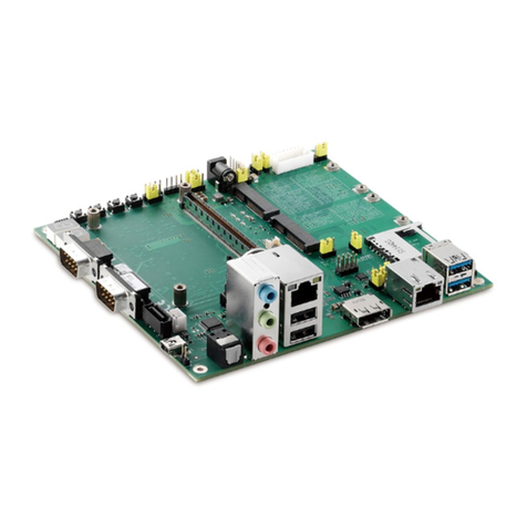
An evaluation carrier SMART-BEE is available for SMARC T335X computer on
module. SMART-BEE has all the interfaces on SMARC T335X module in the
form of either connectors or pin headers and is a good reference for hardware
designers who would like to develop their own carrier boards.
All examples of this document are based on SMART-BEE carrier board that is
available from Embedian. This document also provides a collection of useful
documentation, application reports, and design recommendations.

SMARC T335x Carrier Board Hardware Design Guide, Document Revision 1.2
1.1 Acronyms and Abbreviations Used
Table below shows the acronyms and abbreviations used in this section.
Abbreviation Explanation
ADCAnalogue to Digital Converter
Auto‐MDIXAutomatically Medium Dependent Interface Crossing, a PHY
with Auto-MDIX f is able to detect whether RX and TX need to
be crossed (MDI or MDIX)
CANController Area Network, a bus that is manly used in
automotive and industrial environment
CPUCentral Processor Unit
DACDigital to Analogue Converter
DDCDisplay Data Channel, interface for reading out the capability of
a monitor
DSIDisplay Serial Interface
EDIDExtended Display Identification Data, timing setting information
provided by the display in a PROM
EMIElectromagnetic Interference, high frequency disturbances
eMMCEmbedded Multi Media Card, flash memory combined with
MMC interface controller in a BGA package, used as internal
flash memory
ESDElectrostatic Discharge, high voltage spike or spark that can
damage electrostatic- sensitive devices
GBEGigabit Ethernet, Ethernet interface with a maximum data rate
of 1000Mbit/s
GNDGround
GPIOGeneral Purpose Input/Output, pin that can be configured
being an input or output
HDAHigh Definition Audio (HD Audio), digital audio interface
between CPU and audio codec
HDMIHigh-Definition Multimedia Interface, combines audio and
video signal for connecting monitors, TV sets or Projectors,
electrical compatible with DVI-D

SMARC T335x Carrier Board Hardware Design Guide, Document Revision 1.2
Abbreviation Explanation
I2CInter-Integrated Circuit, two wire interface for connecting low
speed peripherals
I2SIntegrated Interchip Sound, serial bus for connecting PCM
audio data between two devices
JTAGJoint Test Action Group, widely used debug interface
LCDLiquid Crystal Display
LSBLeast Significant Bit
LVDSLow-Voltage Differential Signalling, electrical interface standard
that can transport very high speed signals over twisted-pair
cables. Many interfaces like PCIe or SATA use this interface.
Since the first successful application was the Flat Panel
Display Link, LVDS became a synonymous for this interface. In
this document, the term LVDS is used for the Flat Panel
Display Link interface.
MDIMedium Dependent Interface, physical interface between
Ethernet PHY and cable connector
MDIXMedium Dependent Interface Crossed, an MDI interface with
crossed RX and TX interfaces
MSBMost Significant Bit
MXM3Mobile PCI Express Module (second generation), graphic card
standard for mobile device, the SMARC form factor uses the
physical connector but not the pin-out and the PCB dimensions
of the MXM3 standard.
N/ANot Available
N/CNot Connected
ODOpen Drain
OTGUSB On-The-Go, a USB host interface that can also act as
USB client when connected to another host interface
PCBPrinted Circuit Board
PDPull Down Resistor

SMARC T335x Carrier Board Hardware Design Guide, Document Revision 1.2
Abbreviation Explanation
PHYPhysical Layer of the OSI model
PMICPower Management IC, integrated circuit that manages
amongst others the power sequence of a system
PUPull Up Resistor
PWMPulse-Width Modulation
RGBRed Green Blue, colour channels in common display interfaces
RJ45Registered Jack, common name for the 8P8C modular
connector that is used for Ethernet wiring
RS232Single ended serial port interface
RS422Differential signaling serial port interface, full duplex
RS485Differential signaling serial port interface, half duplex, multi
drop configuration possible
SDSecure Digital, flash memory card
SDIOSecure Digital Input Output, an external bus for peripherals that
uses the SD interface
SOCSystem on a Chip, IC which integrates the main component of
a computer on a single chip
SPISerial Peripheral Interface Bus, synchronous four wire full
duplex bus for peripherals
TVSDiodeTransient-Voltage-Suppression Diode, diode that is used to
protect interfaces against voltage spikes
UARTUniversal Asynchronous Receiver/Transmitter, serial interface,
in combination with a transceiver a RS232, RS422, RS485,
IrDA or similar interface can be achieved
USBUniversal Serial Bus, serial interface for internal and external
peripherals
VDDPositive supply voltage
VGAVideo Graphics Array, analogue video interface for monitors

SMARC T335x Carrier Board Hardware Design Guide, Document Revision 1.2
1.2 Signal Table Terminology
Table below describes the terminology used in this section for the Signal
Description tables.
The “#” symbol at the end of the signal name indicates that the active or
asserted state occurs when the signal is at a low voltage level. When “#” is not
present, the signal is asserted when at a high voltage level.
Direction Type / Tolerance Notes
InputInput to the Module
OutputOutput from the Module
Output
OD
Open drain output from the Module
Bi‐DirBi-directional signal (can be input or output)
Bi‐Dir
OD
Bi-directional signal; output from the Module is
open drain
VDD_IN Signal may be exposed to Module input voltage
range (3.35 to 5.25V)
CMOS 1.8V CMOS logic input and / or output, 1.8V I/O supply
level or tolerance
CMOS 3.3V CMOS logic input and / or output, 3.3V I/O supply
level or tolerance
CMOS
VDD_IO CMOS logic I/O level – set to 3.3V for SMATC
T335X Modules
CMOS
VDD_JTAG_IO VDD_JTAG_IO is 3.3V in SMARC T335X. The
JTAG emulator adjusts to the VDD_JTAG_IO level
provided by the Module, on the JTAG connector
GBE MDI Differential analog signaling for Gigabit Media
Dependent Interface
LVDS AFB LVDS signaling for AFB – may be PCIe, SATA,
USB SS, GBE MDI, MLB or other low voltage high
speed differential physical interface

SMARC T335x Carrier Board Hardware Design Guide, Document Revision 1.2
Direction Type / Tolerance Notes
LVDS LCD LVDS signaling used for LVDS LCD displays
USB DC coupled differential signaling used for
traditional (non- Super-Speed) USB signals
USB SS LVDS signaling used for Super Speed USB 3.0
USB VBUS 5V 5V tolerant input for USB VBUS detection
10/100Base-TX Differential signaling, using MLT-3 (tri level) format
for 100 MBit / Sec full duplex Ethernet
REF Reference voltage output. May be sourced from a
Module power plane.
PDS Pull-down strap. A Module output pin that is either
tied to GND or is not connected. Used to signal
Module capabilities (pin-out type) to the Carrier
Board.
P Power input/output
Schematic examples are drawn with signal directions shown per the figure
below. Nets that connect to the SMARC Module are named per the SGET
SMARC specification.
Figure 1: Schematic Conventions

SMARC T335x Carrier Board Hardware Design Guide, Document Revision 1.2
Power nets are labeled per the table below. The power rail behavior under the
various system power states is shown in the table.
Term S0
On
S3
Suspend
to RAM
S4
Suspend
to Disk
S5
Soft Off
G3
Mechanical
Off
VDD_IN3.35V~5.25
V 3.35V~5.25
V 3.35V~5.25
V 3.35V~5.25
V Off
VDD_505V Off Off Off Off
VDD_333.3V Off Off Off Off
AUD_333.3V Off Off Off Off
VDD_181.8V Off Off Off Off
VDD_RTC3.0V 3.0V 3.0V 3.0V 3.0V

SMARC T335x Carrier Board Hardware Design Guide, Document Revision 1.2
1.3 Document and Standard References
1.3.1. External Industry Standard Documents
The I2C Specification, Version 2.1, January 2000, Philips
Semiconductor (now NXP) (www.nxp.com).
I2S Bus Specification, Feb. 1986 and Revised June 5, 1996, Philips
Semiconductor (now NXP) (www.nxp.com).
MXM3 Graphics Module Mobile PCI Express Module
Electromechanical Specification, Version 3.0, Revision 1.1, © 2009
NVIDIA Corporation (www.mxm-sig.org).
PICMG® EEEP Embedded EEPROM Specification, Rev. 1.0, August
2010 (www.picmg.org).
SD Specifications Part 1 Physical Layer Simplified Specification,
Version 3.01, May 18, 2010, © 2010 SD Group and SD Card
Association (Secure Digital) (www.sdcard.org).
SPI Bus – “Serial Peripheral Interface” - de-facto serial interface
standard defined by Motorola. A good description may be found on
Wikipedia
(http://en.wikipedia.org/wiki/Serial_Peripheral_Interface_Bus).
USB Specifications (www.usb.org).
1.3.2. SGET Documents
SMARC_Hardware_Specification_V1p0, version 1.0, December 20,
2012.
1.3.3. Embedian Documents
The following documents are listed for reference. The Module schematic is
not usually available outside of Embedian, without special permission. The
other schematics may be available, under NDA or otherwise. Contact your
Embedian representative for more information. The SMARC T335X
Evaluation Carrier schematic is particularly useful as an example of the
implementation of various interfaces on a Carrier board.
SMARC_T335X Evaluation Carrier Board Schematic, PDF and
OrCAD format
SMARC_T335X Evaluation Carrier Board User’s Manual
SMARC_T335X Carrier Board Hardware Design Guide
SMARC_T335X Carrier Board Hardware Layout Guide

SMARC T335x Carrier Board Hardware Design Guide, Document Revision 1.2
SMARC_T335X User’s Manual
SMARC_T335X Schematic Checklist
1.3.4. TI Documents
AM335x ARM Cortex-A8 Microprocessors (MPUs), April 15 2013 (rev.
F)
AM335x Schematic Checklist, Oct 31 2011
AM335x ARM Cortex-A8 Microprocessors (MPUs) Technical
References Manual, April 15 2013 (rev. H)
AM335x Power Consumption Summary, Oct 31 2011
1.3.5. TI Development Tools
Pin Mux Utility for ARM® Microprocessors
Power Estimation Tool (PET)
1.3.6. TI Software Documents
LINUXEZSDK-AM335x
ANDROIDDEVKIT-JB-AM335x
1.3.7. Embedian Software Documents
Embedian Linux BSP for SMARC T335X Module
Embedian Android BSP for SMARC T335X Module
Embedian Linux BSP User’s Guide
Embedian Android BSP User’s Guide
1.3.8. TI Design Network
Beaglebone
Adeneo Embedded (Windows Embedded Compact 7)
Nucleus
QNX

SMARC T335x Carrier Board Hardware Design Guide, Document Revision 1.2
1.4 Intended Audience
This design guide is intended for electronics engineers and PCB layout
engineers designing Carrier Boards for SMARC T335X Modules.

SMARC T335x Carrier Board Hardware Design Guide, Document Revision 1.2
Interfaces
This chapter describes the signals and implementation
guideline found on SMARC T335X connectors.
Section includes:
SMARC T335X Connector Pin Mapping
Ethernet Interface
USB Interface
Parallel RGB LCD Interface
SD/SDIO Interface
I2C Audio Interface
CAN BUS Interface
Serial COM Port Interface
SPI Interface
I2C BUS Interface
Selecting the Boot Mode
Watchdog Control Signals
Table of contents
