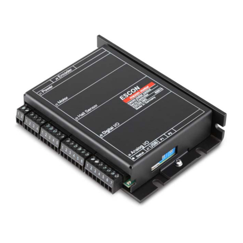
Embention MC24 User manual

MC24
Embention
Dec 14, 2022


CONTENTS
1 Introduction 3
2 Quick Start 5
2.1 Warnings ................................................. 5
2.2 Requirements ............................................... 5
3 Technical 7
3.1 Electrical Specifications ......................................... 7
3.2 Mechanical Specifications ........................................ 10
3.3 System Diagram ............................................. 12
3.4 FOC (Field Oriented Control) Background ............................... 12
3.5 Interfaces ................................................. 13
4 Hardware Installation 15
4.1 Pinout ................................................... 16
4.2 ESC-Motor Wiring ............................................ 19
5 Software Installation 21
6 Maintenance 23
7 Acronyms and Definitions 25
8 Contact Data 27
i

ii

MC24
CONTENTS 1

MC24
2 CONTENTS

CHAPTER
ONE
INTRODUCTION
Veronte MC24 speed controller is capable of driving any type of 3-phase PMSM motor. It can be used with a wide
variety of UAVs or eVTOL vehicles and also in automotive applications (Bikes, Karts, Cars).The MC24 uses FOC
algorithm for motor control together with MOSFET technology.
MC24 Speed Controller offers IP68 protection, allowing the operation under rain and extreme humidity environments.
MC24 Speed Controller working voltage range is 60-120V with a maximum input continuous current of 200A (up to
24kW).
The system has a temperature range of -20 to 55ºC. For higher temperature, a power limitation will be applied.
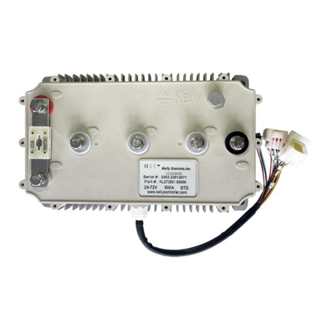
MC24 front view
3

MC24
MC24 rear view
4 Chapter 1. Introduction

CHAPTER
TWO
QUICK START
This document describes the main functionalities of the MC24 Speed Controller.
2.1 Warnings
When installing the MC24 speed controller in the vehicle, the following limitations shall be considered:
•The distance between the battery, the controller system and the motor should be as short as possible in order
to maximize the efficiency. It is preferable to place the controller system as close to the battery as possible and
extend the cables from the controller to the motor. Calibration will be needed depending on the final setup.
•The wire connections type between the power items must be crimped not soldered.
•The system must be placed in a ventilated place with proper air flow. If this is not possible, it is necessary to
install an external fan.
•The vehicle must have an inrush current limiter when powering MC24 for the first time.
•PID tuning is strongly not recommended, since it nullifies the warranty.
•An unappropriated use of the MC24 exempts Embention from responsabilities related to any damage.
Note: When working voltage is higher than 60V, use of insulating gloves are mandatory for installation and the system
must have a chassis fault detection system.
Warning: Careful! The system slowly discharges the voltage on the input terminals when the battery is
disconnected. Capacitors may remain charged unless enough time has passed.
2.2 Requirements
To dissipate the heat from the MC24 properly, there is a need to provide 16m/s of air speed against the heatsink.
5

MC24
Airflow dissipation
6 Chapter 2. Quick Start

CHAPTER
THREE
TECHNICAL
3.1 Electrical Specifications
Table 1: Electrical Characteristics
Type Specification
Voltage 60-120DC
Cont. Current (rms at battery input) 5 - 200A
Peak Current (<5s) 400A
Maximum speed (1 pole) 600000 ERPM
PWM frequency 10 kHz
Weigth 2430g
VCC
This is the main power input for the secondary part of the driver. It must be powered with a voltage of 8 to 20V.
The consumption of this pin also depends on the loads connected to 5V pin.
Status Value
Standby 6.6W
Active 13.2W
Note: No load on 5V output.
HALL Inputs
These inputs are used to add to the system a feedback in sensored mode (incremental type, usually magnetic).
FAN_PWM
This 0-3.3V output is used to control an external fan in case it is needed.
Opto PWM Input
This input is an optocoupled control digital signal.
The input is interpreted as 0-100% of the maximum RPM. An initial dead band can be configured to prevent the engine
from starting.
7

MC24
Table 2: Electrical Characteristics
Type Specification
Input voltage range 0-5V
Minimum input current 2.5mA
Maximum frequency 250Hz
NTC/PTC Input (External Temperature Sensing)
A PTC or NTC sensor can be integrated. The maximum voltage on this pin is 2V.
The PTC/NTC should be connected on the low side of an external resistor divider. This is the configuration by default.
A high side connection can be used too, but a custom modification is needed.
The isolated Voltage_ref output should be left floating in default mode. The iso_ground is the return path of the
NTC/PTC sensor.
ERROR_SIGNAL
This signal indicates if there is an error within the MC24. A positive voltage of 3.3V means that there is no problem.
SIN/COS_SIGNAL
These signals are those dedicated to the SIN / COS type analog sensor. There is a 100K ohms resistor to act as divider
so the maximum voltage on the pin does not exceed ±250mV.
USB
This is the interface normally used to configure the MC24 internal parameters.
The connection and disconnection of the USB related signals should always be done when the power supply (via the
VCC input) is on.
Note: Not recommended for sending telemetry by default.
RS-232
Single ended serial type protocol:
Table 3: Electrical Characteristics
Type Specification
ESD Protection ±15 kV (HBM)
Requirements TIA/EIA-232-F and ITU v.28
Speed Max. 250 kbit/s
Input Voltage -25 to 25V
Output Voltage -13.2 to 13.2V
RS-485
Differential serial type protocol:
8 Chapter 3. Technical

MC24
Table 4: Electrical Characteristics
Type Specification
ESD Protection ±15 kV (HBM)
Requirements TIA/EIA-485-A
Speed Max. 25 Mbit/s
Input Voltage(D) -0.5 to 7V
Output Voltage (D) 1.5 to 2.4V
CAN
Differential communication protocol:
Table 5: Electrical Characteristics
Type Specification
ESD Protection ±4 kV (HBM)
Requirements ISO11898-2
Speed Max. 5 Mbit/s
Input Voltage(D) -12 to 12V
Output Voltage (D) 2.9 to 4.5V
Motor
This tab sets all the physical parameters of the motor that will be used with Veronte MC24. These are:
1. Stator internal resistance: This is the resistance that is usually specified in datasheets. Expressed in Ohms.
2. Quadrature Inductance: Usually called “Lq”. Expressed in Henries (H).
3.1. Electrical Specifications 9

MC24
3. Direct Inductance: Usually called “Ld”. Expressed in Henries (H).
4. Pole pairs: Number of poles divided by two. For instance, if your motor has 42 poles, you must input 21 here.
5. Maximum RPMs: The maximmum RPMs the motor can reach in combination with your propeller. This
parameter is only used to determine the equivalence between the maximum command (PWM or CAN) and
the commanded RPM in speed closed loop mode.
6. Startup Iq: The current used to start the motor.
7. Maximum Iq: Maximum current the speed control loop can command to the quadrature current control loop.
Please refer to FOC background section for further reference.
8. Time to hold Max Iq: Maximum time to hold the previous value before going to off.
Warning: All the current are expressed in amperes/1000. So if in order to input 35 Apk, 0.035 must be typed.
Peripheral used for motor control
•Opto Isolated PWM
•CAN bus
Peripheral use for ESC telemetry
•Serial RS-232
•Serial RS-485
•USB
Any of the serial interfaces can be used to configure the internal variables of the MC24.
The ESC includes an internal SD memory which is used to record operating logs. The variables to store can be selected
through the corresponding interface.
Note: The selected configuration interface cannot be used to send telemetry.
3.2 Mechanical Specifications
•Weight: 2430g.
•Operating temperature: -40°C to 60°C.
•Dimensions:
10 Chapter 3. Technical

MC24
Dimensions
3.2. Mechanical Specifications 11

MC24
3.3 System Diagram
3.4 FOC (Field Oriented Control) Background
In order to achieve better dynamic performance, a more complex control scheme needs to be applied, to control the PM
motor. With the mathematical processing power offered by the microcontrollers, we can implement advanced control
strategies, which use mathematical transformations in order to decouple the torque generation and the magnetization
functions in PM motors. Such de-coupled torque and magnetization control is commonly called rotor flux oriented
control, or simply Field Oriented Control (FOC).
The Field Orientated Control consists of controlling the stator currents represented by a vector. This control is based on
projections which transform a three phase time and speed dependent system into a two co-ordinate (d and q co-ordinates)
time invariant system. These projections lead to a structure similar to that of a DC machine control. Field orientated
controlled machines need two constants as input references: the torque component (aligned with the q co-ordinate)
and the flux component (aligned with d co-ordinate). As Field Orientated Control is simply based on projections the
control structure handles instantaneous electrical quantities. This makes the control accurate in every working operation
(steady state and transient) and independent of the limited bandwidth mathematical model.
A basic scheme for the FOC is represented as follows:
12 Chapter 3. Technical

MC24
As it can be seen, there some key pieces in this algorithm:
1. Park/Clark transform: These output a two co-ordinate time invariant system and a outputs a two co-ordinate
time variant system respectively. As mentioned before, this is part of the process of getting two scalar values
from a three phase time dependent system.
2. PI Controllers: There are three of them: two to control quadrature current and direct current (torque and flux)
and one to control speed. This last one is placed as the one that controls Iq PI (cascade control) which means
that in order to get more speed the system will command more torque (or Iq).
3. Speed estimator: This block is able to estimate mechanical speed from current and voltage using the so-called
“Sliding Mode Observer” algorithm.
The main dificulty of this control proposal is to tune these three PI controller although in most cases both current PI
are exactly the same due to PMSM properties. In addition, there is an extra gain that needs to be tuned as part of the
angular speed estimator algorithm.
This last part is optional but highly recommended in case an external sensor is used such as a hall effect sensor or a
SIN/COS sensor.
3.5 Interfaces
The connectors references are shown in the next figure and table.
3.5. Interfaces 13

MC24
Name Commercial reference Embention reference
Sensor cable FGG.1K.316.CLAC65Z P005591
Phase C Wurth M8 5580870 P005590
Phase B
Phase A
In negative
In positive
User cable FGG.3K.324.CLAC90 P005704
14 Chapter 3. Technical

CHAPTER
FOUR
HARDWARE INSTALLATION
The MC24 system has the following positions of mounting holes:
Mounting Holes
15

MC24
4.1 Pinout
The user connector pinout is shown in the following figures and table:
Point of view
Pin numbers of user connector
16 Chapter 4. Hardware Installation
Table of contents
Other Embention Controllers manuals
