manuals.online logo
Brands
  1. Home
  2. •
  3. Brands
  4. •
  5. Festo
  6. •
  7. Controllers
  8. •
  9. Festo CPX Assembly instructions

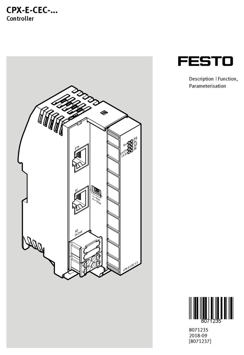
Festo CPX Assembly instructions

Translation of the original instructions
1 Applicable documents
All available documents for the product èwww.festo.com/pk.
Document Product Contents
Description Terminal CPX System, Assembly, Installation, Com
missioning
Description Valve terminal MPALVI
Description Valve terminal MPAF
Description Valve terminal MPAS
System, Assembly, Installation, Com
missioning, conversion, disassembly
Tab. 1
2 Safety
2.1 Safety instructions
– Only assemble the product on components that are in a condition to be safely
operated.
– Observe the handling specifications for electrostatically sensitive devices.
– Plan sufficient space:
– Enable heat dissipation by air circulation è 1 Applicable documents
– Ensure that the connections are accessible
– Requirements for the mounting surface:
– torsionfree operation of the product
– support of the weight and other forces occurring during operation
2.2 Intended use
The CPX terminal with valve terminal MPA1 is referred to as CPX terminal1 in
this instruction manual.
Product Use
CPX terminal1Control of pneumatic actuators. Query of the sensors.
Mounting
2/3/5/6/8/aJ
Additional wall mounting of the valve terminal1.
Tab. 2
3 Product range overview
3.1 Scope of delivery
1Terminal
CPX
with
Valve terminal
MPA
Fig. 1
Wall mounting
Mounting for CPX modules (plastic):
2Mounting
CPXBGRW...
Fig. 2
Mounting for CPX modules (metal):
3Mounting bracket
CPXMBGRW...
4ScrewM3
(threadcutting)
Fig. 3
Mounting for MPALVI modules
5Mounting bracket
VMPALBD
Fig. 4
Mounting for MPAF modules
6Mounting bracket
VMPAFBGRW...
7ScrewM4
(threadcutting)
Fig. 5
Mounting for MPAS proportionalpressure regulator
8Mounting bracket
VMPABG
9ScrewM3
(threadcutting)
Fig. 6
Mounting for MPAS intermediate supply (pneumatic supply plate)
10 Mounting bracket
VMPABGRW...
11 ScrewM3
(threadcutting)
Fig. 7
3.2 Not included
H-rail mounting
12 Hrail(1x)
EN 60715  35x7.5 or 35x15
Fig. 8
Mounting CPXCPABGNRH
13 Screw(3x)
14 Clamping element(3x)
Fig. 9
Mounting VMPAFFBBGNRH
8085254
CPX, CPX-M, MPAL-VI, MPA-F, MPA-S
Terminal CPX / Valve terminal MPA
8085254
201901a
[8085256]
Instructions|Assembly
Festo AG & Co. KG
Ruiter Straße 82
73734 Esslingen
Germany
+49 711 3470
www.festo.com
15 Clamping element MPAF(1x)
16 Screw(1x)
17 Screw(2x)
18 Clamping element CPA(2x)
Fig. 10
4 Mounting
4.1 Wall mounting
4.1.1 Check positions of the mountings
Mountings are preassembled depending on the configuration.
CPX modules: counting direction from the end plate[V]
MPA modules: orientation from the mounting points of the adapter plate[W]
Fig. 11
1. Check positions of the preassembled mountings and correct if required.
2. Assemble by step 3, 4, 5, 6 or 7 depending on the mounting:
3. Positions of mounting2 with CPX modules (plastic)
Number of modules Mounting between the modules
2 and 3 5 and 6 8 and 9
1…2 –
3 •1)
4…5 •
6…8 • •
9…10 • • •
1) This mounting is not required in combination with MPAL valve terminals.
Tab. 3
4. Positions of mounting3 with CPX modules (metal)
Number of modules Mounting to the modules
23467
1…3 –
4 •
5…6 •
7 •
8 • •
9…10 • •
Tab. 4
5. Positions of the mounting5 with MPALVI valve terminal ³ 200 mm
– every 130 mm
6. Positions of the mounting6 with MPAF valve terminal ³ 300 mm
– every 250 mm on subbase
7. Positions of the mounting8/aJ with MPAS valve terminal ³280 mm
– a mounting every 130 mm:
–8 on MPAS proportional pressure regulator or
–aJ on MPAS intermediate supply
With MPAS valve terminals size 14 in
• horizontal or vertical suspended position from mounting point [V] mount
a MPAS intermediate supply after every third module.
• horizontal recumbent position from mounting point [W] mount a MPAS
intermediate supply after every second module.
SG2: total length of valve terminal £ 430 mm
SG1: total length of valve terminal > 430 mm
4.1.2 Assemble mountings
4.1.2.1 Mounting[2] on CPX modules (plastic)
Fig. 12
1. Press mounting2 inclined into the back of the modules[A].
2. Tilt mounting2 until it catches.
3. Install additional mounting2 opposite.
4.1.2.2 Mounting[3] on CPX modules (metal)
For CPX modules (metal) without system supply, the mounting3 can be
assembled on both sides of the module.
Fig. 13
1. Place mounting3 on the module[B].
2. Tighten4 screws. When screwing in again, use the threads already present.
Tightening torque: 1.5Nm ± 10 %
4.1.2.3 Mounting[5] on MPAL-VI modules
Fig. 14
1. Press mounting5 inclined into the back of the modules[C].
2. Tilt mounting5 until it catches.
4.1.2.4 Mounting[6] on MPA-F modules
Fig. 15
1. Place mounting6 on the module[D].
2. Tighten7 screws. When screwing in again, use the threads already present.
Tightening torque: 4Nm ± 20 %
4.1.2.5 Mounting[8] for MPA-S proportional-pressure regulator
Fig. 16
1. Place mounting8 on the module[E].
2. Tighten9 screws. When screwing in again, use the threads already present.
Tightening torque: 1.5Nm ± 10 %
4.1.2.6 Mounting[10] on MPA-S intermediate supply
Fig. 17
1. Place mountingaJ on the module[F].
2. TightenaA screws. When screwing in again, use the threads already present.
Tightening torque: 1.5Nm ± 10 %
4.1.3 Overview of the mounting points
• Select screws suitable for the installation situation.
4.1.3.1 Mounting points of the CPX terminal (plastic) with
MPAL-VI valve terminal
Fig. 18
Mounting point Screw size Number
[G] M6 2x
[H] M4 1x every 2
[N] M6 2x
[P] M6 1x every 5
[L] M6 2x
Tab. 5
4.1.3.2 Mounting points of the CPX terminal (plastic) with
MPA-F valve terminal
Fig. 19
Mounting point Screw size Number
[G] M6 2x
[H] M4 1x every 2
[J] M6 2x
[K] M6 1x every 6
[L] M6 2x
Tab. 6
4.1.3.3 Mounting points of the CPX terminal (metal) with
MPA-F valve terminal
Fig. 20
Mounting point Screw size Number
[G] M6 2x
[M] M6 1x every 3
[J] M6 2x
[K] M6 1x every 6
[L] M6 2x
Tab. 7
4.1.3.4 Mounting points of the CPX terminal (plastic) with
MPA-S valve terminal
Fig. 21
Mounting point Screw size Number
[G] M6 2x
[H] M4 1x every 2
[Q] M4 2x
[R] M6 1x every aJ
[S] M6 1x every 8
[L] M6 2x
Tab. 8
4.1.3.5 Mounting points of the CPX terminal (metal) with
MPA-S valve terminal
Fig. 22
Mounting point Screw size Number
[G] M6 2x
[M] M6 1x every 3
[Q] M4 2x
[R] M6 1x every aJ
[L] M6 2x
Tab. 9
4.2 H-rail mounting
4.2.1 Mount H-rail
Fig. 23
• Mount HrailaB horizontally. Distance between the screws: 50mm
4.2.2 Mount CPX-terminal on H-rail
Fig. 24
• Remove preassembled mountings.
4.2.2.1 H-rail mounting with MPAL-VI or MPA-F valve terminal
Fig. 25
On the back of the modules:
1. Place clamping elementaE on the mounting point[U].
2. Fix clamping elementaE with the screwaF.
3. Place clamping elementsaH on the mounting points[T].
4. Fix clamping elementsaH with screwsaG.
Fig. 26
• Align clamping elementsaE parallel to the slot(Z).
Fig. 27
• Align clamping elementsaH parallel to the slot(Z).
Fig. 28
1. Attach CPX terminal1 to the slot(Z) on the HrailaB.
2. Swivel CPX terminal1 onto the HrailaB.
Fig. 29
•Tighten screwsaF/aG. Tightening torque: 1.3Nm ± 10 %
Fig. 30
Tightening the screwsaF/aG turns the clamping elementsaE/aH 90°. CPX termin
al1 is secured against tilting and slipping.
4.2.2.2 H-rail mounting with MPA-S valve terminal
Fig. 31
1. Place clamping elementsaD on the mounting points[T].
2. Fix clamping elementsaD with screwsaC.
Fig. 32
• Align clamping elementsaD parallel to the slot(Z).
Fig. 33
1. Attach CPX terminal1 to the slot(Z) on the HrailaB.
2. Swivel CPX terminal1 onto the HrailaB.
Fig. 34
•TightenaC screws. Tightening torque: 1.3Nm ± 10 %
Fig. 35
Tightening the screwsaC turns the clamping elementsaD 90°. CPX terminal1 is
secured against tilting and slipping.
5 Technical data
Vibration resistance/
Shock resistance
according to IEC 60068 Wall H-rail
Vibration Part 26 SL21) SG1
Shock Part 227 SG2 SG1
Continuous shock Part 227 SG1 SG1
1) SL1 = severity level 1; SL2 = severity level 2
Tab. 10
Features of severity level (SL)
Vibration load
Frequency range [Hz] Acceleration [m/s2] Deflection [mm]
SL1 SL2 SL1 SL2 SL1 SL2
2…8 2…8 – – ±3.5 ±3.5
8…27 8…27 10 10 – –
27…58 27…60 – – ±0.15 ±0.35
58…160 60…160 20 50 – –
160…200 160…200 10 10 – –
Shock load
Acceleration [m/s2] Duration [ms] Shocks per direction
SL1 SL2 SL1 SL2 SL1 SL2
±150 ±300 11 11 5 5
Continuous shock load
Acceleration [m/s2] Duration [ms] Shocks per direction
±150 6 1000
Tab. 11 Features of severity level (SL)

Other manuals for CPX

5

This manual suits for next models

4

Other Festo Controllers manuals

Festo MPPES 010 Series User manual

Festo

Festo MPPES 010 Series User manual

Festo 03-B User manual

Festo

Festo 03-B User manual

Festo ELGS-TB User manual

Festo

Festo ELGS-TB User manual

Festo DFPD-Series Setup guide

Festo

Festo DFPD-Series Setup guide

Festo DFPI-ND2P Series Setup guide

Festo

Festo DFPI-ND2P Series Setup guide

Festo CMMS-AS G2 Series User manual

Festo

Festo CMMS-AS G2 Series User manual

Festo LR G Series User manual

Festo

Festo LR G Series User manual

Festo CMMS-AS-G2 Series Operating and installation instructions

Festo

Festo CMMS-AS-G2 Series Operating and installation instructions

Festo DFPD-HD-Series User manual

Festo

Festo DFPD-HD-Series User manual

Festo SPC200 Series User manual

Festo

Festo SPC200 Series User manual
Festo CPX-E-CEC-C1-EP Parts list manual

Festo

Festo CPX-E-CEC-C1-EP Parts list manual

Festo CPX-E-CEC EP Series User manual

Festo

Festo CPX-E-CEC EP Series User manual

Festo CMMP-AS-***-M3 Series Operating and installation instructions

Festo

Festo CMMP-AS-***-M3 Series Operating and installation instructions

Festo CLR User manual

Festo

Festo CLR User manual

Festo 32 MPA User manual

Festo

Festo 32 MPA User manual

Festo CMMO-ST-C5-1-LKP User manual

Festo

Festo CMMO-ST-C5-1-LKP User manual

Festo SEC-ST-48-6-P01 Operating and installation instructions

Festo

Festo SEC-ST-48-6-P01 Operating and installation instructions

Festo MPS PA User manual

Festo

Festo MPS PA User manual

Festo DFPD-Series User manual

Festo

Festo DFPD-Series User manual
Festo CMMP Series Operating and installation instructions
Festo

Festo CMMP Series Operating and installation instructions

Festo CECX-K-D1 User manual

Festo

Festo CECX-K-D1 User manual

Festo CMMP-AS Series Reference guide

Festo

Festo CMMP-AS Series Reference guide

Festo SPC200 Series User manual

Festo

Festo SPC200 Series User manual

Festo SLS-6-Series-P-A User manual

Festo

Festo SLS-6-Series-P-A User manual

Popular Controllers manuals by other brands

S&C Micro-AT Quick start programming guide

S&C

S&C Micro-AT Quick start programming guide

TC Electronic DYN 3000 NATIVE quick start guide

TC Electronic

TC Electronic DYN 3000 NATIVE quick start guide

Primex CW6CDC user manual

Primex

Primex CW6CDC user manual

Bartlett Boss Series manual

Bartlett

Bartlett Boss Series manual

Arlight LT3200-350 quick start guide

Arlight

Arlight LT3200-350 quick start guide

BIFFI RPD Series Installation, operation and maintenance manual

BIFFI

BIFFI RPD Series Installation, operation and maintenance manual

Pentair 962 Series Operation manual

Pentair

Pentair 962 Series Operation manual

Zeck Audio F52EQ owner's manual

Zeck Audio

Zeck Audio F52EQ owner's manual

CSZ EZT-550 instruction manual

CSZ

CSZ EZT-550 instruction manual

Carotron RCP200 Series instruction manual

Carotron

Carotron RCP200 Series instruction manual

IRIS Energy Smart ES2H40HD045V Installation, operation and troubleshooting instructions

IRIS

IRIS Energy Smart ES2H40HD045V Installation, operation and troubleshooting instructions

Xantech VCIR-CFL install guide

Xantech

Xantech VCIR-CFL install guide

Siemens RWD44U Application guide

Siemens

Siemens RWD44U Application guide

Siemens Ertec 400 manual

Siemens

Siemens Ertec 400 manual

Larsen & Toubro C*2000 Series user manual

Larsen & Toubro

Larsen & Toubro C*2000 Series user manual

BÜCHI B-720 manual

BÜCHI

BÜCHI B-720 manual

Lenz Digital plus LH101 operating instructions

Lenz

Lenz Digital plus LH101 operating instructions

GYS GYSPACK TRUCK manual

GYS

GYS GYSPACK TRUCK manual

manuals.online logo
manuals.online logoBrands
  • About & Mission
  • Contact us
  • Privacy Policy
  • Terms and Conditions

Copyright 2025 Manuals.Online. All Rights Reserved.