Embraco Scroll SE6015GS-O User manual

FOR EMBRACO SCROLL
REFRIGERATION COMPRESSORS
SCROLL
INSTALLATION
INSTRUCTIONS

2

3
SCOPE OF THE COMPRESSOR INSTALLATION INSTRUCTIONS
These installation instructions applies to Embraco scroll compressors for refrigeration applications. The
Country of Origin is indicated on the compressor label.
It is addressed to professional, commercial refrigeration system manufacturers/installers and maintenance
technicians and intends to provide instructions/recommendations on the proper use of Embraco scroll
compressors regarding reliability, performance and safety aspects.
The information of this these installation instructions is limited to the Embraco scroll refrigeration
compressors and to their installation/operation/service. It is not to be considered comprehensive or as a
set of information for training for technicians that need to be qualified by appropriated training nor to replace
the instruction manual of the final equipments provided by the manufacturers.
All the operation on systems, their production, installation use, repairing and disposal must be carried out
according to all the applicable International and National regulations and standards.
DISCLAIMER
All product specifications and data are subject to change without notice; thus customer should always verify its
latest updates on Embraco website (www.embraco.com), catalogues before relying on them.
The information provided herein is correct to the best of Embraco’s knowledge of typical requirements that
are oen requested to Embraco’s products, It is the customer’s responsibility, relying solely on its own testing
and engineering work, to validate that a particular product with the properties described in Embraco’s product
specification is suitable for use in a particular application, Embraco makes no representation concerning the
suitability of its products for incorporation into or use with customer’s applications.
Parameters provided in datasheets and / or specifications may vary in different applications and performance
over time. Therefore Embraco’s statements related to all operating parameters, including typical parameters,
cannot be intended to replace the customer’s validation for each application by the customer’s technical experts.
Product specifications do not expand or otherwise modify Embraco’s terms and conditions of purchase, including
but not limited to the warranty expressed therein.
Embraco rejects any liability for damages and injures caused by its products and/or the applications they are
embedded into being installed or repaired by untrained personnel and/or in discordance with these safety
instructions.

4
GENERAL INDEX
1 SAFETY....................................................................................................p. 07
1.1 Safety notice ...........................................................................................p. 07
1.2 Safety advice ..........................................................................................p. 07
1.3 Safety instructions ................................................................................p. 08
2 PRODUCT INTRODUCTION ........................................................ p. 09
2.1 Compressor test condition ................................................................... p. 11
2.2 Compressor cooling types ....................................................................p. 11
3 COMPRESSOR APPLICABLE STANDARDS AND REGULATIONS.... p. 11
4 EMBRACO RELEVANT DOCUMENTS ......................................... p. 11
5 COMPRESSOR NOMENCLATURE .............................................. p. 12
5.1 Compressor model code ....................................................................... p. 12
5.2 Compressor Bill of material code ........................................................p. 12
5.2.1 Compressor size......................................................................................p. 12
5.2.2 Voltage and frequency supply .............................................................p. 13
5.2 3 External execution .................................................................................p. 13
5.2.4 Electrical execution ...............................................................................p. 13
5.2.5 Accessories execution ...........................................................................p. 14
5.2.6 Packaging execution .............................................................................. p. 14
5.3 Compressor label ................................................................................... p. 14
5.3.1 Serial number code ................................................................................ p. 15
6 PRODUCT DESCRIPTION......................................................................p. 15
6.1 Application description ..........................................................................p. 15
6.2 Approved refrigerants.............................................................................p. 16
6.2.1 Refrigerants general information.........................................................p. 17
6.3 External dimensions...............................................................................p. 18
6.4 Hermetic terminal dimensions ............................................................p. 19
6.5 Sight glass ...............................................................................................p. 20
6.6 Free internal volume ..............................................................................p. 20
7 TECHNICAL SPECIFICATIONS.............................................................p. 21
8 OPERATING CONDITIONS....................................................................p. 22
8.1 Ambient temperature.............................................................................p. 22
8.2 Compressor selection.............................................................................p. 22
8.3 Supply voltages and frequencies ......................................................... p. 23
8.4 Operating envelopes ..............................................................................p. 24
8.5 Low ambient operation..........................................................................p. 25
8.6 Refrigerant charge..................................................................................p. 25
8.7 Crankcase heater.................................................................................... p. 26
8.8 Accumulators ..........................................................................................p. 27
8.9 Pump down recommendations.............................................................p. 27
8.10 Compressor On/Off cycling ...................................................................p. 28
8.11 Shell temperrature ................................................................................p. 28
8.12 Maximum discharge gas pressures and temperatures ..................... p. 28
8.13 Discharge line thermostat ....................................................................p. 29
8.13.1 Discharge line thermostat for LBP .......................................................p. 29
8.13.2 Discharge line thermostat for MBP...................................................... p. 29

5
8.14 Pressure controls.................................................................................... p. 30
8.15 Internal pressure relief valve (IPR Valve).............................................p. 30
9 INSTALLATIONS..................................................................................... p. 30
9.1 System components compatibility ...................................................... p. 30
9.2 Painting ...................................................................................................p. 31
9.3 Grommets and sleeves ..........................................................................p. 31
9.4 Mounting for rack systems .................................................................... p. 31
9.5 Screens..................................................................................................... p. 32
9.6 Liquid injection .......................................................................................p. 32
9.7 Solenoid valve ......................................................................................... p. 33
9.8 Current sensing relay ............................................................................. p. 33
9.9 Temperature responsive expansion valve ...........................................p. 33
9.10 Suggested application techniques .......................................................p. 34
9.11 Compressor or valve service ................................................................. p. 34
9.12 Connectors ..............................................................................................p. 35
9.12.1 Compressor pressurization .................................................................... p. 35
9.12.2 Connectors brazing process ..................................................................p. 35
9.12.3 Tube brazing ............................................................................................ p. 36
9.12.4 Tube disconnects .................................................................................... p. 36
9.12.5 Tubing selection .....................................................................................p. 36
9.13 Connections.............................................................................................p. 37
9.14 Rotolock valves ....................................................................................... p. 38
9.15 Adapters...................................................................................................p. 38
10 ELECTRICAL SPECIFICATIONS ....................................................................p. 39
10.1 Electrical motor types ........................................................................... p. 39
10.2 Electrical components types ................................................................p. 40
10.2.1 Electrical components specification of single phase .........................p. 40
10.3 Electrical connections and wiring diagrams ....................................... p. 41
10.4 Motor protection .....................................................................................p. 42
10.4.1 Overload protector parameters.............................................................p. 42
10.5 Degree of protection .............................................................................p. 42
10.6 CSR box .................................................................................................... p. 43
10.7 Fusite pin ................................................................................................p. 43
10.8 Terminal cover mounting and removal ................................................p. 44
10.9 Three-Phase rotation direction ............................................................ p. 44
10.10 Brief power interruptions ......................................................................p. 45
10.11 Electrical supply line and cabinet supply cable ..................................p. 45
10.12 Maximum temperature of electric motor windings ............................p. 45
10.13a Electrical data of three phase motor.................................................... p. 46
10.13b Electrical data of single motor..............................................................p. 47
10.14 Definitions................................................................................................ p. 47
10.15 High potential (Hi-pot) testing ..............................................................p. 47
10.16 Electrical connections ............................................................................ p. 48
10.17 Screws tightening torque ......................................................................p. 48
10.18 Electrical insulation ................................................................................ p. 49
11 STARTING PROCEDURE ............................................................. p. 49
11.1 System cleanliness ................................................................................p. 49
11.2 Moisture removal ................................................................................... p. 49
11.3 System evacuation ................................................................................. p. 50
11.4 Deep vacuum operation ........................................................................p. 50
11.5 Dehydration.............................................................................................p. 50
11.6 Charging process .................................................................................... p. 51

6
11.7 Oil charge ................................................................................................p. 51
11.7.1 Oil Management for rack application ................................................... p. 52
11.8 Scroll functional check .......................................................................... p. 52
11.9 Starting sound level ...............................................................................p. 52
11.10 Sound generation in refrigeration system ........................................... p. 53
12 MAINTENANCE (COMPRESSOR REMOVAL AND REPLACEMENT) .. p. 53
12.1 Compressor replacement procedure ................................................... p. 55
12.2 Unbrazing system components ............................................................p. 55
13 HOW TO RETURN SUPPLIED PRODUCTS TO EMBRACO EUROPE . p. 56
14 COMPRESSOR DISPOSALS ...........................................................p.57
15 COMPRESSOR PACKAGING ............................................................... p.57
15.1 Multiple (industrial) packaging .............................................................p. 57
15.2 Single packaging .................................................................................... p. 57
16 HANDLING. TRANSPORTATION AND STORAGE.............................p.59
16.1 Handling...................................................................................................p. 59
16.2 Storage..................................................................................................... p. 59
16.3 Storage conditions .................................................................................p. 60
16.4 Transportation .......................................................................................p. 60
16.4.1 Shipment by container ..........................................................................p. 60
16.4.2 Shipment by truck ..................................................................................p. 61
16.4.3 Acceptable compressor positions during transportation
of finished product .................................................................................p. 61
16.4.4 Acceleration during transport and handling ....................................... p. 61
APPENDIX 1 – SAFETY RECOMMENDATIONS FOR COMPRESSOR INSTALLATION ......... p. 62
DIGITAL TOOLS ..............................................................................................................p. 67
ATEL: Acute-toxicity Exposure Limit
AHRI: Air-Conditioning, Heating and
Refrigeration Institute (formerly)
CSR (CSCR): Capacitive Start & Run
(Capacitor Start - Capacitor Run)
DTC: Discharge Temperature Control Valve
EN: European Standards
GFCI: Ground Fault Circuit Interrupter
GWP: Global Warming Potential
HFC: HydroFluoroCarbon
HFO: HydroFluoroOlefin
ID: Internal Diameter
IP: International Protection (ratings)
IPRV: Internal Pressure Relief Valve
ISO: International Organization of
Standardization
ISPM: Regulation of Wood packaging
Material in International Trade
LBP: Low Back Pressure
LCL: Less Then Container Load
LFL: Lower Flammability Limit
LRA: Locked Rotor Amps
LVD: Low Voltage Directive
MBP: Medium Back Pressure
MCC: Maximum Continuous Current
MD: Machine Directive
MOC: Maximum Operating Current
MSDSs: Material Safety Data Sheets
OD: Outside Diameter
ODL: Oxygen Deprivation Limit
ODP: Ozone Depletion
OFDN: Oxygen-Free-Dry-Nitrogen
OLP: Overload Protector
PED: Pressure Equipment Directive
POE: Polyolester
RCD: Residual Current Device
REACH: Regulation on Registration,
Evaluation, Authorization and Restriction of
Chemicals
RLA: Rated Load Amperage
RoHS: Restriction of Hazardous Substances
Directive
SH: Superheating
TXV: Thermostatic Expansion Valve
3Ø: Three-phase
Terms and Definitions
For the refrigeration system terms used in these Scroll installation instructions, refer to EN 378-1 or similar
standards.
ACRONYMS USED IN THE TEXT

7
1. SAFETY
1.1 SAFETY NOTICE
Embraco compressors are designed, manufactured and inspected according to the latest European
applicable standards, with particular care on the user’s safety.
Embraco compressors are designed as refrigerant pumping elements on refrigeration machines. Only if they
are used for this purpose and installed according to the instructions of these installation instructions and
the applicable regulations and standards can be put in service, as indicated on the Embraco Manufacturers
Declaration of Incorporation according the 2006/42/EC Machinery Directive.
These instructions should be retained throughout the lifetime of the compressor. You are strongly advised
to follow these safety instructions, and also the local related rules should be obeyed.
Technicians are strongly advised to follow the entire applicable International and National laws and
regulation as well as the instructions of these installation instructions.
1.2 SAFETY ADVICE
WARNING: Indicates Instructions that may result in personal injury or death and
property damage if not carefully followed.
CAUTION: indicates instructions that may results in property damage and possible
personal injury if not carefully followed.
IMPORTANT: indicates instruction to avoid damages/malfunction of the
compressors.
WARNING
CAUTION
IMPORTANT

8
1.3 SAFETY INSTRUCTIONS
Safety statements
• Refrigerant compressors must be used only for their intended use.
• Only qualified/certified and authorized refrigeration technicians are permitted
to perform installation and maintenance of compressors.
• Electrical connections must be made by qualified electrical technicians.
• All valid standards for installing, servicing, and maintaining of electrical and
refrigeration equipment must be observed.
• Usage of personal safety equipment is recommended (goggles, gloves, clothing,
boots and hard hats)
Electrical shock hazard
• Turn off power before servicing.
• Discharge all capacitors.
• Use compressor with grounded system only.
• Molded electrical plug must be used when required.
• Refer to original equipment wiring diagrams.
• Electrical connections must be made by qualified electrical personnel.
• Use only components approved by manufacturer.
• Failure to follow these warnings could result in serious personal injury.
Pressurized system hazard
• System contains refrigerant and oil under pressure.
• Remove refrigerant from both the high and low pressure side before removing
compressor.
• Use appropriate back up wrenches on Rotolock fittings when servicing.
• Never install a system and leave it unattended when it has no charge,
a holding charge, or with the service valves closed without electrically locking
out the system.
• Use only approved refrigerants and refrigeration oils.
• Failure to follow these warnings could result in serious personal injury.
Burn hazard
• Do not touch the compressor until it has cooled down.
• Ensure that materials and wiring do not touch high temperature areas of
the compressor.
• Use caution when brazing system components.
• Failure to follow these warnings could result in serious personal injury or
property damage.
For the compressor connection to the electrical supply line and for maintenance/
repairing operations, refer also to Appendix 1 - Recommendations - safety
instruction for compressor installation.
WARNING
WARNING

9
2. PRODUCT INTRODUCTION
Embraco offers a full range of hermetic reciprocating compressors for refrigeration from fractional
horse power (hp) up to 1.5hp with a long experience in developing innovative solutions for commercial
and professional refrigeration.
With the new range of scroll compressors for refrigeration Embraco complete the product range for
commercial and professional applications with a range of scroll compressors from 2hp up to 13hp
working with R404A, R452A, R449A, R448A and R134a, R513A (MBP only).
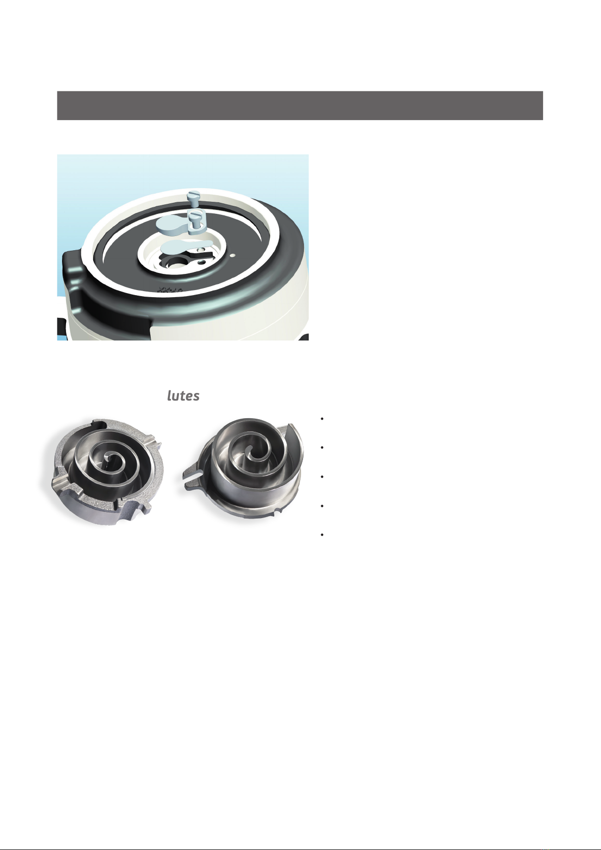
By visualizing the whole cycle of a scroll mechanism, we can notice that 3 phases: suction, compression
and discharge are simultaneously made in a continuous movement.
It represents numbers of advantages:
• Less parts in movement versus other compressor technologies; the compression system is
composed by only the mobile and the fix scroll.
• There is no dead space, the volumetric efficiency is close to 1.
• The absence of re-expansion loss makes that there is no reduction of the isentropic efficiency.
• The perfect suction system symmetry by two points diametrically opposed and discharge by
the center of spirals assure a functioning with much lower pulsations and noise.
LBP section MBP section
Figure 2.0 Product sections
10
DESIGN FEATURES
• Dynamic valve specially designed for
MBP/LBP working conditions - allows
high compression ratio reducing
compression.
• Instant shutdown.
• More efficient for pump down control.
• Designed for higher motor efficiency in different condition.
• Designed to ensure uniform three phase motor winding temperature.
• Build-in overload protector.
• Unique design with dual compliance – radial
and axial.
• Effective control of discharge temperature
to improve compressor reliability.
• Specially designed for Mid/Low
temperatures compression ratio.
• Height-thickness ratio to assure strength
of involutes.
• High isentropic efficiency design.
Figure 2.0.1. Discharge valve
Figure 2.0.2 Involutes
2.0.3 Motor
11
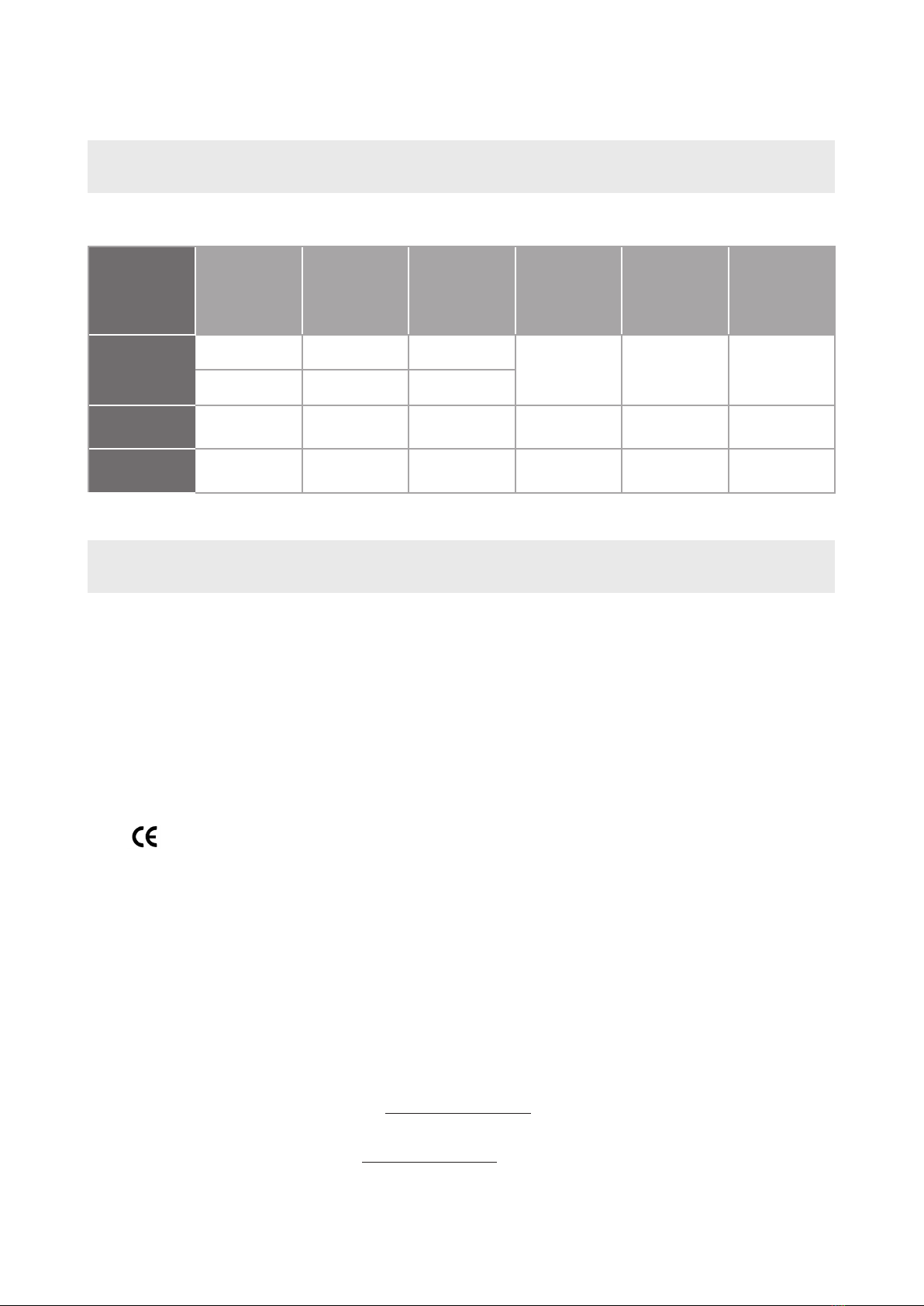
2.1 COMPRESSOR TEST CONDITION
Table 2.1 Test condition
TEST
CONDITIONS
RATING POINT
APPLICATION
EVAPORATING
TEMPERATURE
°C
CONDENSING
TEMPERATURE
°C
RETURN GAS
TEMPERATURE
°C
SUBCOOLING
AMBIENT
TEMPERATURE
°C
EN 12900
LBP -35 40
20 NO
SUBCOOLING 35
MBP -10 45
ARI 540
2015 LBP -31.6 40.6 4.4 NO
SUBCOOLING 35
ARI 540
2004 HBP -6.7 54.4 48.9 NO
SUBCOOLING 35
2.2 COMPRESSOR COOLING TYPES
Scroll compressors are designed as static, not requiring forced ventilation cooling. Its cooling is secured by
refrigerant. Ambient temperature has very little impact on compressor performance.
3. COMPRESSOR APPLICABLE STANDARDS AND
REGULATIONS
4. EMBRACO RELEVANT DOCUMENTS
• Embraco Product Selector on www.embraco.com
• Scroll Installation instructions.
Check available documents on www.embraco.com or contact Embraco Technical support team.
Compressors comply with the latest European standards and regulations and are marked with
mark.
• Low Voltage Directive 2014/35/EU.
• Machinery Directive 2006/42/EC.
• Pressure Equipment Directive (PED) 2014/68/UE.
• RoHS II Directive 2011/65/EU.
• REACH Regulation (EC) 1907/2006.

12
5. COMPRESSOR NOMENCLATURE
Information printed on compressor label: model, voltage and frequency supply, bill of material.
5.1 COMPRESSOR MODEL CODE
COMPRESSOR SCROLL
TYPE
PACKAGING EXECUTION
ACCESSORIES EXECUTION
VOLTAGE & FREQUENCY SUPPLY
COMPRESSOR SIZE
EXTERNAL EXECUTION
ELECTRICAL EXECUTION
MODEL CODE
30 1A C 01 01 AA
COMPRESSOR FAMILY
SE = Scroll Embraco
VOLTAGE & FREQUENCY SUPPLY
C - 220V 50Hz 1~
O - 380-420V 50Hz/460V 60Hz 3~
NOMINAL CAPACITY
In Btu/h at 60 Hz x 1000
ARI conditions
E.g. 015=15000 Btu/h
APPLICATION CODE
2 = LBP
6 = MBP
REFRIGERANT
R404A, R452A, R449A, R448A, R134a, R513A
SE 2015 GK C
5.2 COMPRESSOR BILL OF MATERIAL CODE
5.2.1 COMPRESSOR SIZE
1– MBP models for 2-6hp
2– MBP models for 7-13hp
3– LBP models for 2-6hp
4– LBP models for 7-13hp

13
5.2.3 EXTERNAL EXECUTION
Table 5.2.4
5.2.4 ELECTRICAL EXECUTION
5.2.2 VOLTAGE AND FREQUENCY SUPPLY
Table 5.2.2
VOLTAGE CODE RATED VOLTAGE & FREQUENCY
C220V 50HZ 1~
O380420V 50HZ / 460V 60HZ 3~
Table 5.2.3
EXTERNAL
EXECUTION
COMPRESSOR
SIZE
APPLICATION CONFIGURATION TYPE
01 2-6 hp MBP Brazing connection; discharge tube ID Ø12.92mm ±5; suction tube ID Ø22.4mm ±5;
oil sight glass.
02 2-6 hp LBP Brazing connection; discharge tube ID Ø12.92mm ±5; suction tube ID Ø22.4mm ±5;
Liquid Injection with DTC valve; oil sight glass.
03 7-13 hp LBP Brazing connection; discharge tube ID Ø22.47mm; suction tube ID Ø28.83mm; Liquid
Injection with DTC valve; oil sight glass.
04 7-13 hp MBP Brazing connection; discharge tube ID Ø22.47mm; suction tube ID Ø28.83mm; oil sight
glass.
11 2-6 hp MBP Rotolock connection; threaded discharge connection 3/4“-16 UNF 2A, ID Ø9mm; threaded
suction connection 1 1/4“-12 UNF 2A, ID Ø19.2mm; oil sight glass.
12 2-6 hp LBP
Rotolock connection; threaded discharge connection 3/4“-16 UNF 2A, ID Ø9mm;
threaded suction connection 1 1/4“-12 UNF 2A, ID Ø19.2mm; Liquid injection with DTC
valve; oil sight glass.
13 7-13 hp LBP
Rotolock connection; threaded discharge connection 1 1/4“-12 UNF 2A, ID Ø19.2mm;
threaded suction connection 1 3/4“-12 UNF 2A, ID Ø26.4mm. Liquid Injection with DTC
valve; oil sight glass.
14 7-13 hp MBP Rotolock connection; threaded discharge connection 1 1/4“-12 UNF 2A. ID Ø19.2mm;
threaded suction connection 1 3/4“-12 UNF 2A, ID Ø26.4mm; oil sight glass.
EXECUTION
MOTOR TYPE CONFIGURATION TYPE
01 3 PHASE Internal overload protector, terminal cover with gasket and wiring diagram, grounding screw.
04 1 PHASE CSR CSR box with start and run capacitor, Internal overload protector, terminal cover with gasket and wiring diagram,
grounding screw.

14
5.3 COMPRESSOR LABEL
Figure 5.3 Label
Table 5.2.5
Table 5.2.6
5.2.5 ACCESSORIES EXECUTION
5.2.6 PACKAGING EXECUTION
EXECUTION
CONFIGURATION TYPE
AGrommets, sleeves, tube plug, DTC valve included for LBP
EXECUTION
PCS PER PALLET
A9
B12 (for compressors 7-13 hp)
C16 (for compressors 2-6 hp)
Note: See Chapter 15 for detailed information about packaging.
* Manufacturing Date is part of Serial Number Code.
Compressor model
Displacement
Compressor protection
Bill of Materials code
Serial Number Code*
Oil initial
charge
Oil type
Maximum Operating Pressures
(Low and High Side)
Rated Load Amps (RLA)
Locked Rotor Amps (LRA
Voltage & Frequency Supply

15
YEAR / MONTH / DAY
PRODUCTION LINE
5.3.1 SERIAL NUMBER CODE
C170503 0061
SEQUENCE NUMBER
6. PRODUCT DESCRIPTION
6.1 APPLICATION DESCRIPTION
Each compressor model is intended for specific refrigerant and application. Their
use in different application and/or with different refrigerant may result in significant
impact to motor-compressor performance, life expectancy or even may result in
personal injury and damages.
LBP (Low Back Pressure) scroll compressors are designed to correspondent to the latest scroll technology
of refrigeration for low temperature application; including special scroll set design, dynamic discharge valve
and injection system. These special designs result in a compressor that is suitable for the most demanding
refrigeration applications with efficiencies comparable to the semi-hermetic piston compressors.
LBP models are optimized for low temperature applications with discharge
temperature management, working down to -40°C of evaporating temperature;
for instance commercial and professional refrigeration application, frozen food
cabinets, frozen food display cases, cold rooms, frozen products, environmental
test chambers.
MBP (Medium Back Pressure) scroll compressors are designed to correspondent to the latest scroll
technology of refrigeration for medium temperature applications.
MBP models are optimized for medium temperature applications, able to run
down to -30°C of evaporating temperature without injection solution; for instance
commercial and professional cabinets, fresh products cabinets, ice machines, milk
coolers and cold room.
WARNING

16
Table 6.2 Approved refrigerants
6.2 APPROVED REFRIGERANTS
Usage of different refrigerants can generate abnormal working conditions, excessive
pressure in the refrigeration system, damages of the compressor and explosions.
All operations related to the use of refrigerants shall be performed only by trained
and qualified technicians and in accordance with applicable International and
National standards, laws and regulations related to this subject.
Users must have available and understand the applicable HFCs Material Safety
Data Sheets (MSDSs).
When selecting the refrigerant, it is important to measure different aspects the environment would require:
legislations, standards, cost, availability, and surely the applications. Thanks to its specific technology, the
scroll allows the compressor to run as multi refrigerant product, Embraco has therefore qualified the range
with the following refrigerants:
WARNING
WARNING
APPLICATION
REFRIGERANTS
R404A R452A R449A R448A R134a R513A
LBP ✓ ✓ ✓ ✓ X X
MBP ✓✓✓✓✓✓
R404A is an HFC refrigerant without any ozone depletion (ODP=0) and suitable for medium temperature and
low temperature applications, it is near an azeotropic mixture and the glide effect is negligible. It has to be
charged in liquid phase.
R452A is a HFC/HFO blend, it contains R125/R32/R1234yf, but belong to A1 safety class (GWP: 2140; ODP:
0), originally developed for transport application, it can also be used in commercial refrigeration in both
medium and low temperature applications with similar performances than R404A. It can therefore be used in
new installations as well as retrofit of existing installations.
R449A is a HFC/HFO blend, it contains R125/R32/R134a/R1234yf, low GWP (1397), no ozone depletion
(ODP=0) and belong to A1 safety class. It can be used for medium and low applications.
The impact of its glide (6,1K) and higher discharge temperature has to be taken consideration for retrofit; an
audit of the heat exchangers, expansion devices has to be done before final decision.
R448A is a non flammable HFC/HFO blend. It contains R125/R32/R134a/R1234yf/R1234ze, low GWP (1387),
no ozone depletion (ODP=0) and belong to A1 safety class. It can be used for medium and low applications.
The impact of its glide (6,3K) and higher discharge temperature has to be taken consideration for retrofit;
an audit of the heat exchangers, expansion devices has to be done before final decision.
R134a is a pure refrigerant with zero glide and low GWP (1430), it is only qualified for medium temperature
application.
R513A is a HFO refrigerant, it contains R1234yf/R134a, low GWP (631), no ozone depletion (ODP=0) with
zero glide and belong to A1 safety class. It is qualified for medium temperature application, suitable for new
installations as well as retrofit of existing installations.

17
6.2.1 REFRIGERANTS GENERAL INFORMATION
Table 6.2.1
Refrigerant glide - Single component refrigerants evaporates and condense at constant temperature,
bubble point temperature and dew point temperature are the same. Some refrigerants mixtures, classified
as zeotropic refrigerants, have a measurable temperature change during evaporation or condensing process.
This temperature change is described as "glide“. The "glide“ depends on the mixture substances and their
compositions. As a consequence of "glide“, different temperatures are measured at inlet and outlet of heat
exchangers. For correct performance evaluation of zeotropic refrigerants with the glide more than 1K, the
average evaporator temperature and average condenser temperature shall be considered.
ACCORDING TO
EN378 R404A R452A R449A R448A R134aR513A
CHEMICAL
NAME
Mixture
R125/R143a/
R134a
Mixture
R32/R125/
R1234yf
Mixture
R32/R125/
R1234yf/ R134a
Mixture
R32/R125/
R1234yf/R134a/
R1234ze (E)
1,1,1,2
tetrafluoro-
ethane
Mixture
R134a/R1234yf
MOLECULAR
FORMULA
Weight %
(44/52/4)
Weight %
(11/59/30)
Weight %
24.3/24.7/
25.3/25.7
Weight %
(26/26/20/21/7) CH2FCF3 Weight %
(44/56)
SAFETY CLASS A1 A1 A1 A1 A1 A1
PED FLUID GROUP 2 2 2 2 2 2
PRACTICAL LIMIT
[kg/m3] 0.52 0.423 0.357 0.388 0.25 0.319
ATEL/ODL
[kg/m3]0.52 0.423 0.357 0.388 0.21 0.319
LFL [kg/m3]NF * NF * NF * NF * NF * NF *
VAPOUR DENSITY
25°C,
101.3 KPA [kg/m3]
3.99 4.30 3.62 3.58 4.17 4.256
MOLECULAR MASS
[g/mol] 97.6 103.51 8 7. 21 86.28 102 108.4
NORMAL BOILING
POINT
°C
46.5 to 45.7 47 to 43.2 46 to 39.9 45.9 to 39.8 26 29.05
ODP 0 0 0 0 0 0
GWP
[100 yr ITH] 3922 2140 1397 1387 1430 631.4
AUTOIGNITION
TEMPERATURE
°C
728 ND ND ND 743 ND
CRITICAL
TEMPERATURE
°C
72.12 74.9 81.5 83.7 101.06 96.5
CRITICAL PRESSURE
[kPa abs] 3734.9 4001.7 4447 4660 4059.3 3766
TEMPERATURE
GLIDE AT 1 BAR ABS
PRESSURE K
0.75 0.38 0.61 0.63 00.1
(*) NF signifes non-flammable.
Note: HFC refrigerants (R404A, R452A, R449A, R448A, R134a and R513A) are classified in Safety Class A1 -
lower toxicity, no flame propagation, (according to ISO817).
18
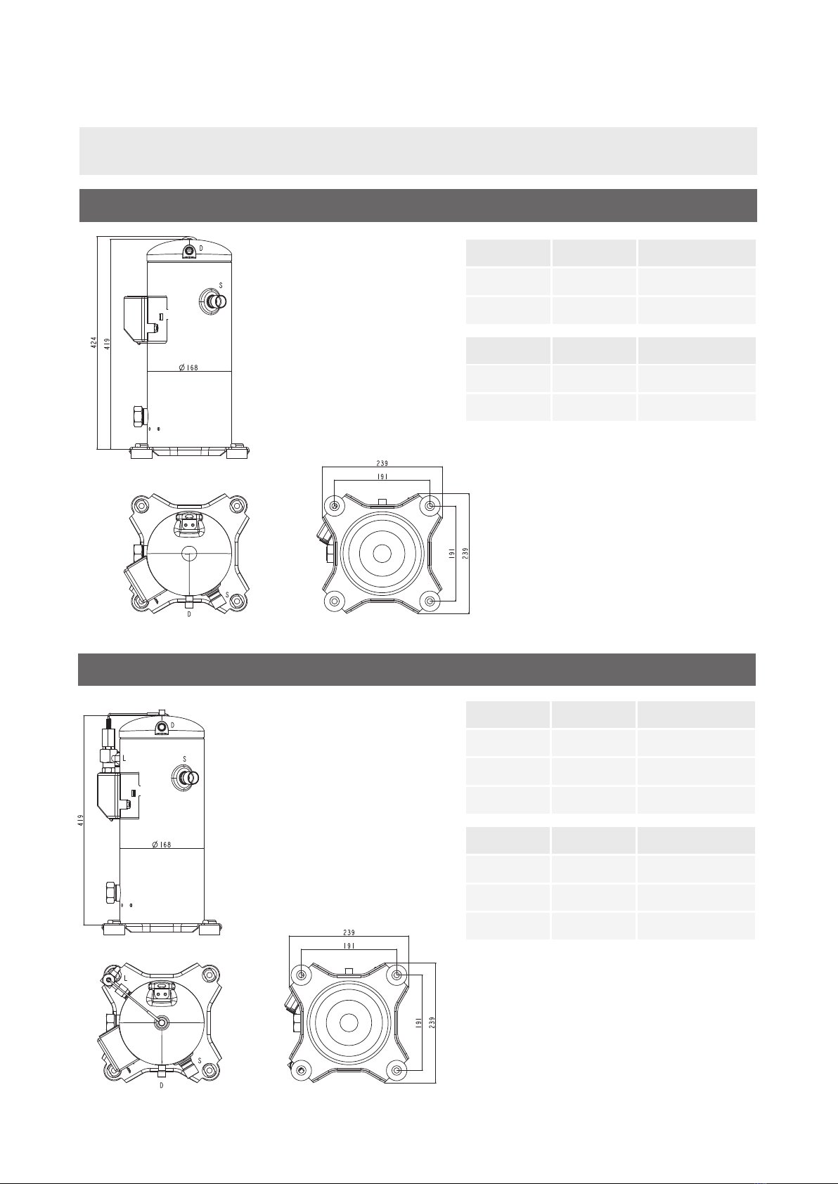
6.3 EXTERNAL DIMENSIONS
MBP_2-6 HP
BRAZING I.D. mm MATERIAL
S - SUCTION 22.35-22.45 COPPER PLATED STEEL
D - DISCHARGE 12.87-12.97 COPPER PLATED STEEL
ROTOLOCK I.D. inches MATERIAL
S - SUCTION 1 1/4"12UNF2A STEEL
D - DISCHARGE 3/4"16UNF2A STEEL
LBP_2-6 HP
BRAZING I.D. mm MATERIAL
S - SUCTION 22.35-22.45 COPPER PLATED STEEL
D - DISCHARGE 12.87-12.97 COPPER PLATED STEEL
L - LIQUID INJ. 3/8" COPPER PLATED STEEL
ROTOLOCK I.D. inches MATERIAL
S - SUCTION 1 1/4" 12UNF 2A STEEL
D - DISCHARGE 3/4" 16UNF 2A STEEL
L - LIQUID INJ. 3/8" STEEL

19
6.4 HERMETIC TERMINAL DIMENSIONS
Figure 6.4 Hermetic terminal
BRAZING I.D. mm MATERIAL
S - SUCTION 22.35-22.45 COPPER PLATED STEEL
D - DISCHARGE 12.87-12.97 COPPER PLATED STEEL
ROTOLOCK I.D. inches MATERIAL
S - SUCTION 1 1/4"12UNF2A STEEL
D - DISCHARGE 3/4"16UNF2A STEEL
MBP_7-13 HP
BRAZING I.D. mm MATERIAL
S - SUCTION 28.83 COPPER PLATED STEEL
D - DISCHARGE 22.47 COPPER PLATED STEEL
ROTOLOCK I.D. inches MATERIAL
S - SUCTION 1 3/4" 12UN STEEL
D - DISCHARGE 1 1/4" 12UNF 2A STEEL

20
Table 6.6b Compressor free internal volume for 1 phase motor
Table 6.6a Compressor free internal volume for 3 phase motor
6.5 SIGHT GLASS
Compressors are equipped and delivered with threaded
oil sight glass of size 1 ¼” 12UNF.
It can be used for visual check of oil, its quantity,
composition or used for parallel multi compressor
connections. Recommended size of wrench for sight
glass nut is 36mm applying torque 55÷60Nm.
6.6 FREE INTERNAL VOLUME
COMPRESSOR SIZE
FREE INTERNAL VOLUME L
LOW SIDE HIGH SIDE
2 HP 4.1 1
2.5 3 HP 3.8 1
3.5 5 HP 3.6 1
6 HP 3.2 1
7 HP 7.3 0.9
8 9 HP 6.5 0.9
10 13 HP 6.3 0.9
COMPRESSOR SIZE
FREE INTERNAL VOLUME L
LOW SIDE HIGH SIDE
2 3 HP 3.6 1
3.5 4 HP 3.2 1
Figure 6.5 Sight glass
This manual suits for next models
29
Table of contents
Other Embraco Air Compressor manuals


Popular Air Compressor manuals by other brands

 Instruction manual and safety instructions")


DeWalt
DeWalt DXCMH1608WB instruction manual

Bitzer
Bitzer 0 operating instructions

Gardner Denver
Gardner Denver ELECTRA-SAVER II Operating and service manual

Craftsman
Craftsman 921.152150 owner's manual

Parkside
Parkside PVKO 50 A1 Translation of the original instructions

Panasonic
Panasonic DA73C12RCU6 Specification sheet