EMBRON Hatteland Technology Series 1 User manual
Please visit www.hattelandtechnology.com for the latest electronic version of this manual.
JH 19T14 STD-AA1-AAAA - 19.0 inch Industrial Display (STD)
Series 1 - Industrial STD Models
USER MANUAL
User Manual STD Series 1
Updated: 03 Feb 2022 Doc Id: INB100036-2 (Rev 9)
Created: 7495/363 Approved: 6987

Copyright © 2021 Hatteland Technology AS
Eikeskogvegen 52, N-5570 Aksdal, Norway.
All rights are reserved by Hatteland Technology AS. This information may not, in whole or in part, be
copied, photocopied, reproduced, translated or reduced to any electronic medium or machine-
readable form without the prior written consent of Hatteland Technology AS. Review also:
www.hattelandtechnology.com/hubfs/pdf/misc/doc100703-1_permission_to_create_user_manuals.pdf
The products described, or referenced, herein are copyrighted to the respective owners.
The products may not be copied or duplicated in any way. This documentation contains proprietary
information that is not to be disclosed to persons outside the user’s company without prior written consent
of Hatteland Technology AS.
The copyright notice appearing above is included to provide statutory protection in the event of
unauthorized or unintentional public disclosure.
All other product names or trademarks are properties of their respective owners !
WARNING: This is a class A product. In a domestic environment this product may cause radio interference
in which case the user may be required to take adequate measures.
Statement above last revised 31 Jul. 2019

3
IND100130-32
Contents.......................................................................................... 3
Contents of package ..................................................................................5
General ............................................................................................ 7
About this manual ......................................................................................8
About Hatteland Technology ......................................................................8
www.hattelandtechnology.com...................................................................8
Contact Information....................................................................................8
Basic Construction .....................................................................................9
Product Labeling ......................................................................................10
Front Logo Label ..........................................................................12
Installation..................................................................................... 13
Installation and mounting .........................................................................14
Ergonomics ..............................................................................................14
Cables......................................................................................................16
Cable Entries & Connectors (Marked area) - Illustration only ......16
Maximum Cable Length ...............................................................16
Rotary Bracket and Mounting Bracket - assembling/nalization..............17
Physical Connections - STD Based Models ............................................19
Operation....................................................................................... 21
User Controls ...........................................................................................22
Status LED Overview...............................................................................24
OSD Menu Overview ...............................................................................25
OSD Menu Quick Start ............................................................................25
OSD Functions Map ................................................................................26
OSD Password / Keycode .......................................................................26
Specications ............................................................................... 39
Specications - JH 19T14 STD-AA1-AAAA.............................................40
Technical Drawings ...................................................................... 41
Technical Drawings - JH 19T14 STD-AA1-AAAA ....................................42
Contents

Contents
4
IND100130-32
Technical Drawings - Accessories.............................................. 43
Technical Drawings - JH 19TSV STD-A1.................................................44
Sun Visor - 19” .............................................................................44
Technical Drawings - JH MMDRO STD-A1..............................................45
Rotary Bracket - 17” to 26”...........................................................45
Technical Drawings - JH MMDBR STD-A1 ..............................................46
Mounting Bracket - 17” to 20”.......................................................46
Technical Drawings - JH 19TAP STD-A1.................................................47
CRT Adapter - 19” TFT to 21” ......................................................47
Technical Drawings - JH 19TAP STD-B1.................................................48
CRT Adapter (Custom) - 19” TFT to 21” ......................................48
Technical Drawings - JH 19VED STD-A1 ................................................49
VESA Adapter - 19”......................................................................49
Technical Drawings - JH 19TWC STD-B1 ...............................................50
Water Cover (HW01) - 19” ...........................................................50
Appendixes ................................................................................... 51
Pin Assignments - Common Connectors .................................................52
Pin Assignments - Multifunction Cable Outputs .......................................53
Basic Trouble-shooting ............................................................................54
Declaration of Conformity ........................................................................55
Return Of Goods Information...................................................................56
General Terms and Conditions ................................................................57
Pixel Defect Policy ...................................................................................58
Notes........................................................................................................59
Revision History .......................................................................................61
5
IND100131-18
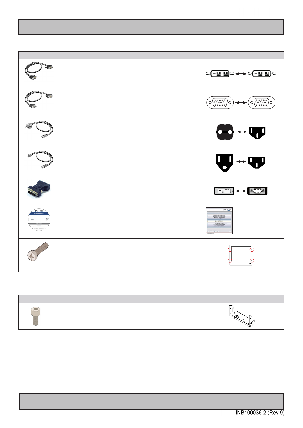
Contents of package
Item Description Illustration
HA-SDM-2M
1 pcs of Standard DVI Signal Cable.
DVI-D 18+1P Male to DVI-D 18+1P Male Single Link- Length 2.0m
HA-VGA-2M-32
1 pcs of Standard VGA Signal Cable.
DSUB 15P Male to DSUB 15P Male - Length 2.0m
FS-CABLE EU
1 pcs of power cable European Type F “Schuko” to IEC.
Length 1.8m
EUR TYPE F
IEC
80099
1 pcs of power cable US Type B plug to IEC.
Length 1.8m
US TYPE B IEC
DVI-4
1 x DVI-I > RGB/VGA adapter
DVI-I 24+5P (Dual Link) Male to DSUB 15P Female
MEDIA STD01
Documentation and Driver DVD/CD containing the user manual, including the Touch
Screen driver for units delivered with a factory mounted touch screen.
Menu and Driver browser
for
Microsoft® Windows®
1P06025 (screw) &
16M06012150 (washer)
4 pcs of M6X25 pan screws.
Suitable for securing the display unit into a console cut-out. See illustration to the right.
DO NOT USE THESE TO MOUNT BRACKETS ONTO THE UNIT.
Use the provided and dedicated screws for accessories (see next table below)
This product is shipped with:
Item Description Illustration
4 pcs of M6X12 Unbraco bolts.
These are included with mounting bracket, if ordered. (See illustration to the right)
Should only be used to secure the bracket onto display.
If you prefer your own bolts, make sure they do not exceed 12mm in length. Use any longer
is not possible due to mechanical limits.
Package may also include:

6
This page left intentionally blank

7
General
8
Hatteland Technology AS
IND100077-1
General
About this manual
The manual contains electrical, mechanical and input/output signal specications. All specications in this manual,
due to manufacturing, new revisions and approvals, are subject to change without notice. However, the last updated
and revision date of this manual are shown both on the frontpage and also in the “Revision History” chapter. This
user manual is a standard/general manual that applies to all variations of its product family, i.e. deviation from actual
conguration may exist.
About Hatteland Technology
Hatteland Technology is the leading technology provider of specialized display and computer products, delivering high
quality, unique and customized solutions to the international maritime, naval and industrial markets.
The company represents innovation and quality to the system integrators worldwide. Effective quality assurance and
investment in sophisticated in-house manufacturing methods and facilities enable us to deliver Type Approved and Mil
tested products. Our customer-oriented approach, technical knowledge and dedication to R&D, makes us a trusted
and preferred supplier of approved solutions, which are backed up by a strong service network.
www.hattelandtechnology.com
You will nd our website full of useful information to help you make an informed choice as to the right product for your
needs. You will nd detailed product descriptions and specications for the entire range on Displays, Computers,
Panel Computers and Military solutions as well as the range of supporting accessories. The site carries a wealth of
information regarding our product testing and approvals in addition to company contact information for our various
oces around the world, the global service locations and the technical support centre, all ensuring the best possible
support wherever you, or your vessel, may be in the world.
Contact Information
Head oce, Aksdal / Norway:
Hatteland Technology AS
Eikeskogvegen 52
N-5570 Aksdal, Norway
Switchboard:
Tel: +47 4814 2200
mail@hattelandtechnology.com
Sales oce, Frankfurt / Germany:
Hatteland Technology GmbH
Werner Heisenberg Strasse 2,
D-63263 Neu-Isenburg, Germany
Elke Freisens:
Tel: +49 173 6174753
Sales oce, Oslo / Norway:
Hatteland Technology AS
Strandveien 35
N-1366 Lysaker
Norway
Switchboard:
Tel: +47 4814 2200
mail@hattelandtechnology.com
Sales oce, Aix-en-Provence / France:
Hatteland Technology SAS
Actimart- 1140, rue Ampère, CS 80544
13594 Aix-en-Provence, Cedex 3
France
Mehdi Bounoua (Sales Director Europe, Middle East & Africa):
Tel : +33 6 88 33 64 93
Sales oce, Vista / USA:
Hatteland Technology Inc
450 South Melrose Drive,
Suite #107
Vista, CA 92081
USA
Donna Pallonetti:
Tel: +1 858-282-0659
Fax: +1 858-408-1834
For an up-2-date list, please visit https://www.hattelandtechnology.com/contact
9
IND100077-75
General
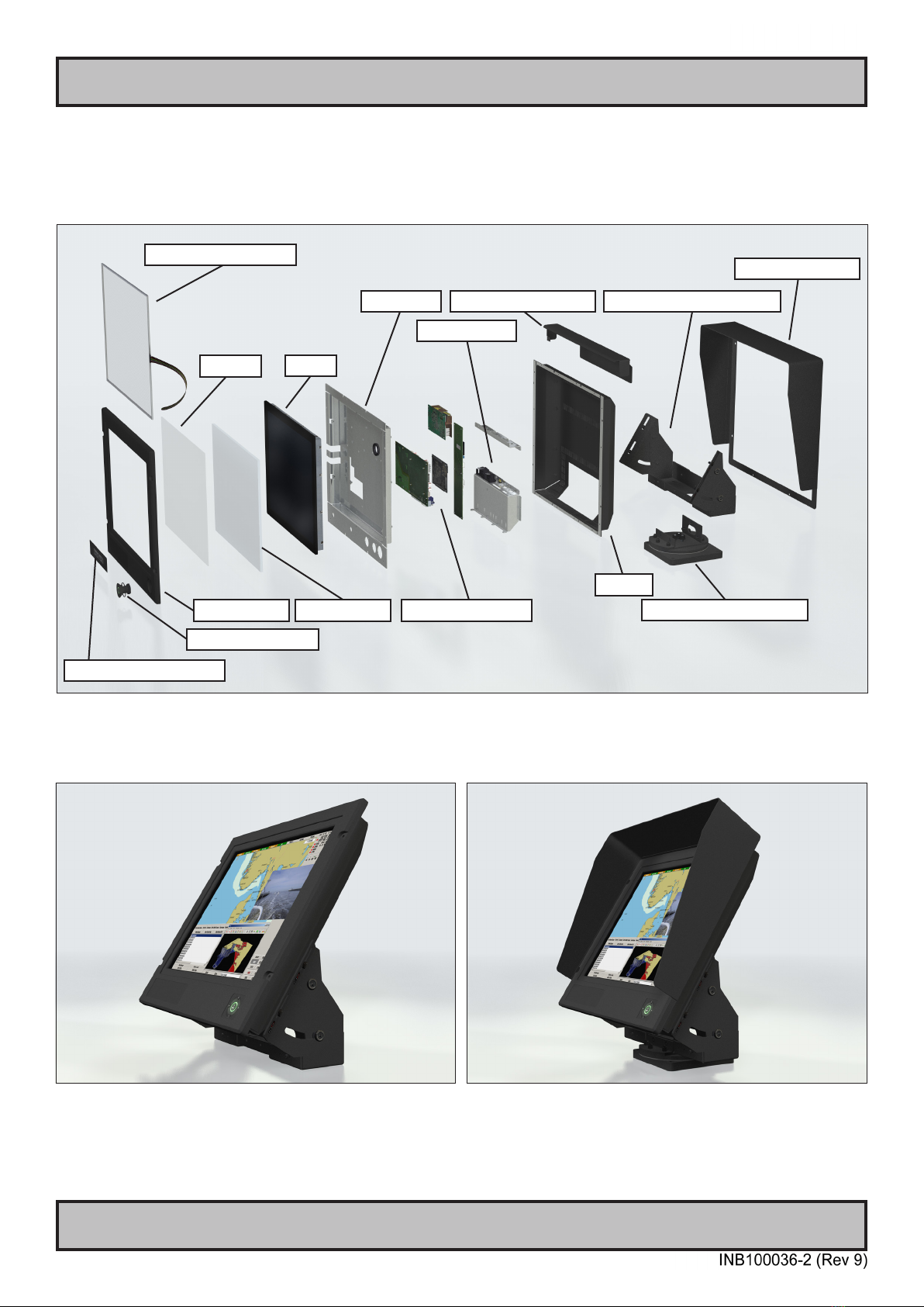
Basic Construction
Basic Construction - Series 1
TFT
Centerbox
Casing
Touch Screen (option)
Logo label (option)
Front Frame
User Controls
Electronics / PCB’s
Glass
Mechanics
Rotary Bracket (option)
Mounting Bracket (option)
Sun Visor (option)
Example with mounting bracket Example with sun visor, mounting bracket and rotary bracket
Bonding
Water Cover (option)

10
IND100077-143
Product Labeling
Introduction
This section details the locations, content details and specications for factory mounted labels for all currently
available standard Hatteland Display Industrial Display (STD) models. This information will in most cases also apply
for most Customized Models as well, but may dier based on customer requirements, in that case, please refer to the
customized User Manual (paper or electronic version, dependent on customer requirements).
Label Size and Types
ID Label Layout Description Specication
Manufacturer: Product: 100W 115VAC/60Hz
Hatteland Display 19,0 Inch 230VAC/50Hz
NORWAY TFT
Date: 20110526
Serial Number:
JH 19T14 STD-AA1-AAAA-000256
Type : Serial Number Label
Name : Label D
Size : 75mm wide x 60mm high (square size)
Note: Text content of label will match specications
derived from Data Sheet.
Silver with glue on back, non-
tearable and made for thermal
transfer printing.
Barcode type: CODE128 (used extensively world wide in shipping and packaging
industries. The symbology was formerly dened as ISO/IEC 15417:2007.)
Type : Warranty Label
Size : 30mm wide x 23mm high (oval size)
Tamper-proof sticker with glue on
back.
Type : Quality Control (QC) Label
Size : 30mm wide x 23mm high (oval size)
Ordinary sticker with glue on
back.

11
Product Labeling
IND100077-143
Label Locations
Number ID and coloring based on “Label Size and Types“ table from previous page. All illustrations below are seen
from rear (and side where needed) with connectors facing down. Actual labels regarding its size and text orientation
vs product size is drawn in. Due to space restrictions on selected units, some labels will be rotated 90 degrees to t
properly. The arrangement of labels may be shifted/stacked dierently as it is based on factory options, such as; Touch
Screen, but they will be grouped together where possible.
Label Positions Notes Applies for Product Range
Warranty label covers screw.
Labels placed on rear.
JH 19T14 STD-xxx-Axxx
12
Product Labeling
IND100077-137
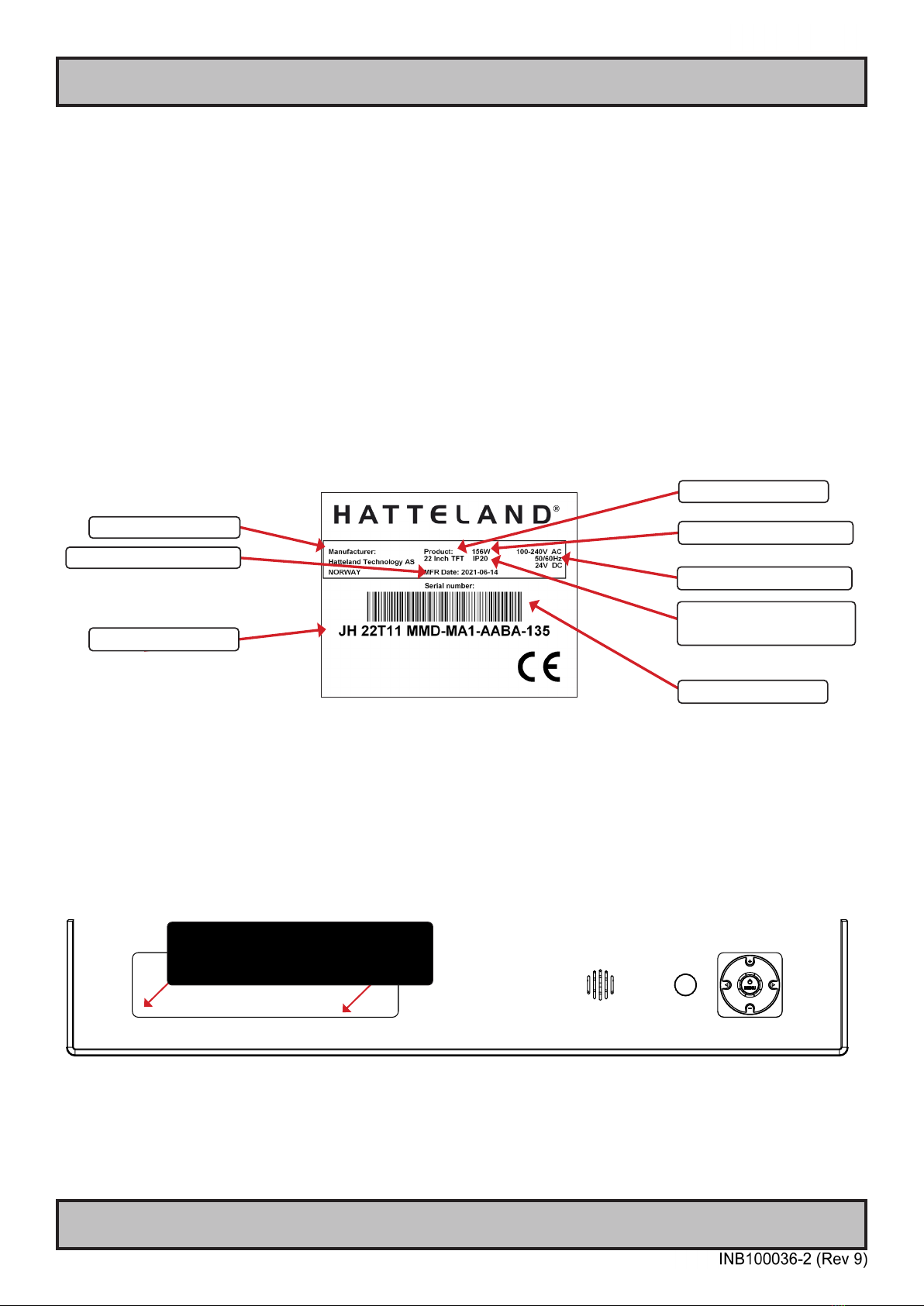
Serial Number Label Layout (example)
Warranty Label
If you are to perform service on a unit still under warranty, any warranty will be void if this label show signs of removal
attempts or damaged by screw driver. This label is located on the back of the product and covers a key screw. This is
to aid service departments in determining if there has been any unauthorized service on a unit still under warranty.
Quality Control (QC) Label
This label indicates that the unit is produced, tested and packed according to the manufacture’s QA specications. It
will include a Personal ID and signature by the personnel responsible for approving the unit in production, testing and
warehouse departments.
Handling Symbols Label
Ecodesign Requirements for Electronic Displays. The European Union published the Regulation 2019/2021 with
specic environmental ecodesign requirements for various types of electronic displays, such as TVs, monitors, and
digital signage displays.
Reference: https://www.enviropass.ca/2021/03/01/5-ecodesign-requirements-for-electronic-displays/
Manufacturer/Country
Product Description
Type+Serial Number
Barcode (TYP+SNO)
Front Logo Label
The front frame bezel design oers an area for customized logo label. These labels can be ordered and customized
with your own logo delivered from us The measurements are as follows.
WxH = 181.66 x 44.16mm / 7.15” x 1.74”. R4.10 - 4 places in each corner. Depth of area is 0.5mm.
Please note that typenumber shown above is a generic sample only. May not reect products mentioned in this
manual. Please review actual product S/N label.
Input Voltage(s)
Power Rating Max/Typ
Date of Production (YYYY-MM-DD)
IP Rating
Lowest value used, higher may apply,
check specications.

13
Installation

14
IND100078-19
Installation
Installation and mounting
1. Most of our products are intended for various methods of installation or mounting (panel mounting, bracket
mounting, ceiling/wall mounting etc.); for details, please see the relevant mechanical drawings.
2. Adequate ventilation is a necessary prerequisite for the life of the product. The air inlet and outlet openings must
denitely be kept clear; coverings which restrict ventilation are not permissible.
3. Generally, do not install the unit in a horizontal position (laying down), as this will cause heat to build up inside the
unit which will damage the LCD Panel. To prevent this problem we recommend installing the unit in a vertical
position (±30 degrees) to improve the airow through the unit.
4. To further improve the cooling of the unit we recommend installing Cooling Fans underneath blowing upwards into
the unit air inlet. This may be required in high temperature applications and also when there is reason to expect
temperature problems due to non-optimal way of mounting.
5. Exposure to extreme direct sunlight can cause a considerable increase in the temperature of the unit, and might
under certain circumstances lead to excessive temperature. This point should already be taken into consideration
when the bridge equipment is being planned (sun shades, distance from the windows, ventilation, etc.)
6. Space necessary for ventilation, for cable inlets, for the operating procedures and for maintenance, must be
provided.
7. If the push buttons of the product are not illuminated, an external, dimmable illumination (IEC 60945 Ed. 4, 4.2.2.3,
e.g. Goose neck light) is required for navigational use. The illumination should be free from glare and adjustable to
extinction.
8. Information about necessary pull-relievers for cables is indicated in the Physical Connection section of this manual.
Attention must be paid to this information so that cable breaks will not occur, e.g. during service work.
9. Do not paint the product. The surface treatment inuences the excess heat transfer. Painting, labels or other
surface treatments that dier from the factory default, might cause overheating.
10. Exposure to heavy vibration and acoustic noise might under certain circumstances aect functionality and
expected lifetime. This must be considered during system assembly and installation. Mounting position must be
carefully selected to avoid any exposure of amplied vibration.
Ergonomics
1. Adjust the unit height so that the top of the screen is at or below eye level. Your eyes should look slightly
downwards when viewing the middle of the screen.
2. Adjust screen inclination to allow the angle of gaze to remain at the centre of the screen approximately
perpendicular to the line of gaze.
3. When products are to be operated both from a sitting position and from a standing position, a screen inclination of
about 30° to 40° (from a vertical plane) has turned out to be favourable.
4. The brightness of displays is limited. Sunlight passing directly through the bridge windows - or its reection - which
falls upon the screen workplaces must be reduced by suitable means (negatively inclined window surfaces,
benetian blinds, distance from the windows, dark colouring of the deckhead).
5. The use of ordinary commercial lter plates or lter lms is not permitted for items of equipment that require
approval (by optical eects, “aids” of that kind can suppress small radar targets, for example).
General Installation Recommendations

15
IND100078-19
General Installation Recommendations
Installation
General mounting instructions
1. The useful life of the components of all Electronics Units generally decreases with increasing ambient temperature;
it is therefore advisable to install such units in air-conditioned rooms. If there are no such facilities these rooms
must at least be dry, adequately ventilated and kept at a suitable temperature in order to prevent the formation of
condensation inside the display unit.
2. With most Electronic Units, cooling takes place via the surface of the casing. The cooling must not be impaired by
partial covering of the unit or by installation of the unit in a conned cabinet.
3. In the area of the wheel house, the distance of each electronics unit from the magnetic standard compass or the
magnetic steering compass must not be less than the permitted magnetic protection distance. This distance is
measured from the centre of the magnetic system of the compass to the nearest point on the corresponding unit
concerned.
4. Units which are to be used on the bridge wing must be installed inside the “wing control console” protected against
the weather. In order to avoid misting of the viewing screen, a 25 ... 50 W console-heating (power depending on the
volume) is recommended.
5. When selecting the site of a display unit, the maximum cable lengths have to be considered.
6. When a product is being installed, the surface base or bulkhead must be checked to ensure that it is at in order to
avoid twisting of the unit when the xing screws are tightened, because such twisting would impair mechanical
functions. Any unevenness should be compensated for by means of spacing-washers.
7. Products with AC input must be grounded to protective Earth (Safety Ground) when necessary via the bolt (usually
on terminal plate) available on the product.
Products with DC input must be grounded to protective Earth (Safety Ground) via the bolt (usually on terminal
plate) available on the product.
A shorter and thicker cable gives better grounding. A 6mm² is recommended, but a 4mm² or even 2.5mm² can be
used for this purpose.
8. Transportation damage, even if apparently insignicant at rst glance, must immediately be examined and be
reported to the freight carrier. The moment of setting-to-work of the equipment is too late, not only for reporting the
damage but also for the supply of replacements.
9. The classication is only valid for approved mounting brackets provided by Hatteland Display. The unit shall be
mounted stand-alone without any devices or loose parts placed at or nearby the unit. Any other type of mounting
might require test and re-classication.
16
IND100078-19
General Installation Recommendations
Installation
Cables
Use only high quality shielded signal cables.
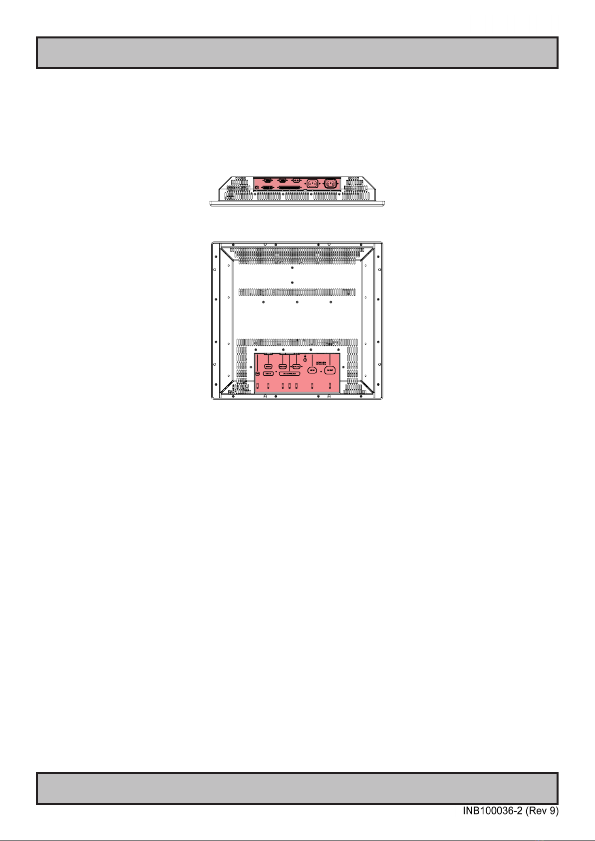
Cable Entries & Connectors (Marked area) - Illustration only
Bottom View
Back View
Maximum Cable Length
Any cable should generally be kept as short as possible to provide a high quality input/output. The maximum signal
cable length will depend not only on the signal resolution and frequency, but also on the quality of the signal output
from the computer/radar. Recommended refresh rate is 60Hz. Cables up to 10 meters generally provides good picture
quality even with a 1600x1200 (UXGA) 60Hz signal. In most cases (especially with lower resolutions) even longer
cables will provide a satisfactory result. This should however be tested in advance before making the decision on how
far the unit can be placed from the signal source.
17
General Installation Recommendations
Installation
IND100078-26
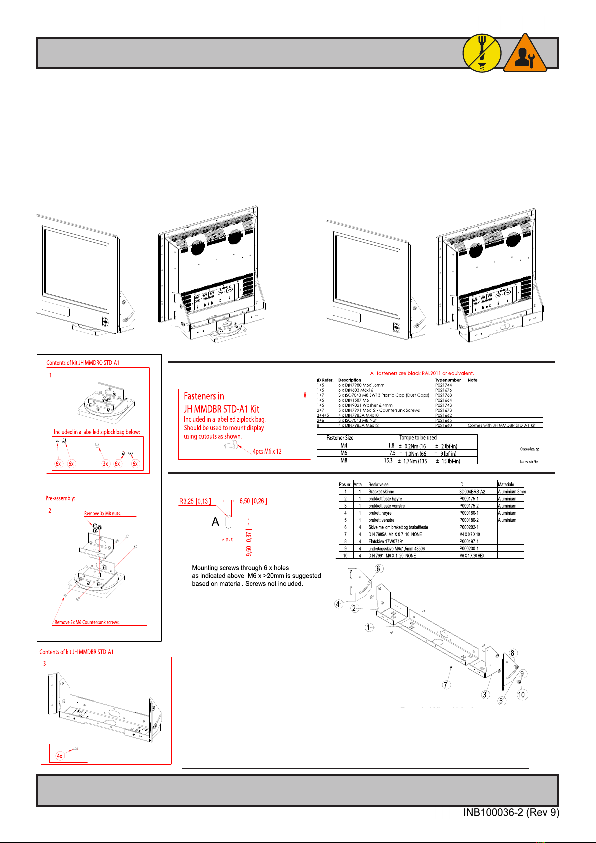
Rotary Bracket and Mounting Bracket - assembling/nalization
Illustration shows Mounting Bracket “JH MMDBR STD-A1” / “JH 23TBR T01” and “Rotary Bracket JH MMDRO STD-A1” combined and not
combined. The brackets are available separately and may be delivered in parts. Some disassembly/assembly is required. Use the provided screws/
bolts/nuts included in the package. A stand-alone “Rotary Bracket” can not be mounted to a Display or Panel Computer unit without the “Mounting
Bracket” as base first. For alternative drawings / measurements of the brackets, review sales drawing (available on internet or inside user manual).
The procedure applies for Display and Panel Computers of sizes: 17, 18, 19, 20 and 23 inch.
You must provide your own bolts to secure the completed unit (#A) to the mounting location. Recommended size to mount complete unit is:
M10 and minimum 30mm in length. If no Rotary Bracket is present or needed, the completed unit (#B) should be mounted at location with M6
>20mm in length depending on material of table/desktop etc.
Hatteland Technology AS
Eikeskogvegen 52
N-5570 Aksdal
Hatteland Technology AS
Eikeskogvegen 52
N-5570 Aksdal
Hatteland Technology AS
Eikeskogvegen 52
N-5570 Aksdal
Hatteland Technology AS
Eikeskogvegen 52
N-5570 Aksdal
Example #A: Mounting Bracket + Rotary Bracket Example #B: Mounting Bracket only
Tip:
If you need to combine Mounting Bracket “JH MMDBR STD-A1” / “JH 23TBR T01” with Rotary Bracket
“JH MMDRO STD-A1” onto Display or Panel Computer unit, please follow Step 1 to 8.
If you need to mount only Mounting Bracket “JH MMDBR STD-A1” to unit, please follow Step 3-4 and Step 5
(re-attach 4 x screws after adjustment based on product size).
Hatteland Technology AS
Eikeskogvegen 52
N-5570 Aksdal
Hatteland Technology AS
Eikeskogvegen 52
N-5570 Aksdal
JH MMDBR STD-A1
JH 23TBR T01
Hatteland Technology AS
Eikeskogvegen 52
N-5570 Aksdal

18
General Installation Recommendations
Installation
IND100078-26
Hatteland Technology AS
Eikeskogvegen 52
N-5570 Aksdal
Hatteland Technology AS
Eikeskogvegen 52
N-5570 Aksdal
Hatteland Technology AS
Eikeskogvegen 52
N-5570 Aksdal
Hatteland Technology AS
Eikeskogvegen 52
N-5570 Aksdal
Hatteland Technology AS
Eikeskogvegen 52
N-5570 Aksdal
Hatteland Technology AS
Eikeskogvegen 52
N-5570 Aksdal
23”
JH MMDBR STD-A1
JH 23TBR T01
19
IND100133-34
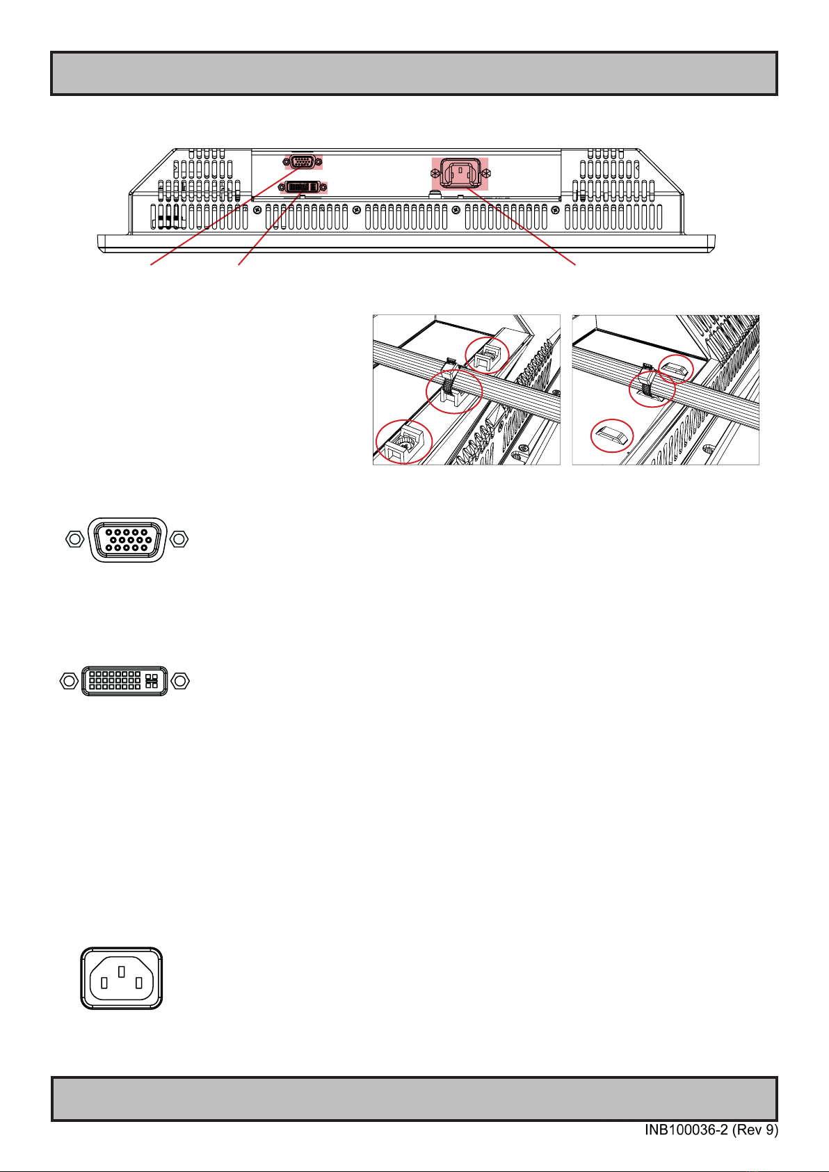
RGB IN AC Power Input
Connection area of display (illustration)
Cable Tension
To reduce tension on the cables you connect,
secure them with a cable tie to the base
mounted clamp or to the chassis hinges.
For certain models a base mounted clamp
is available (FIG 1). For other models a hinge
in the chassis is available (FIG 2).
FIG 1 FIG 2
Physical Connections - STD Based Models
DVI-I IN
RGB IN:
Connect the VGA cable to the D-SUB 15P Connector (female). Secure the VGA cable to the hex spacers provided on
the unit and make sure you do not bend any of the pins inside the connector when connecting. Connect the other end
of the cable to the VGA connector on your equipment and secure it.
DVI-I IN:
Connect your DVI cable to the DVI-I 29P Connector (female). The DVI-I connector can function as regular RGB IN by
using a DVI-I > RGB/VGA adapter. Secure the DVI cable to the hex spacers provided on the unit and make sure you
do not bend any of the pins inside the connector. Connect the other end of the cable to the DVI connector on your
equipment and secure it.
Important note for DVI signal detection:
Please note that for the operating system to detect DVI signals correctly, the DVI cable MUST be connected physically
to the display unit during boot up otherwise you may experience a black image. Furthermore certain graphics drivers
may need to refresh their device list (often done manually by user - detect devices), while in some cases the
Plug-n-Play will automatically detect the DVI signal correctly. Please consult your local technician if you have this
behavior of detection problems when using DVI. In all cases the problem can be solved in the operating system, and
this is not a malfunction in the graphic controller for HATTELAND® units.
POWER INPUT: (For models supporting AC input)
The internal AC power module supports both 115VAC/60Hz and 230VAC/50Hz power input.

20
This page left intentionally blank
This manual suits for next models
1
Table of contents
Other EMBRON Marine Equipment manuals


Popular Marine Equipment manuals by other brands


CORRECT CRAFT
CORRECT CRAFT LINC PANORAY 2020 owner's manual

olympia electronics
olympia electronics BS-531/1 manual

Argus Security
Argus Security CWS100 quick start guide

Raymarine
Raymarine ST60+ SPEED INSTRUMENT quick start guide

Harken
Harken 1561 instructions

olympia electronics
olympia electronics ΒS-532/WP quick start guide