EMBRON Hatteland Display Maritime Multi Computer X... User manual
Hatteland Display AS, Eikeskogvegen 52, N-5570 Aksdal, Norway
Tel: (+47) 4814 2200 - mail@hatteland-display.com - www.hatteland-display.com
HD 07T22 MMC-xxx-xxxx - 7.0 inch Maritime Multi Computer
HD 13T22 MMC-xxx-xxxx - 13.3 inch Maritime Multi Computer
Series X - Maritime Multi Computer (MMC) Models
USER MANUAL
Please visit www.hatteland-display.com for the latest electronic version of this manual.
User Manual MMC Series X Compact
Updated: 26 Oct 2018 Doc Id: INB100485-4 (Rev 03)
Created: 363
Approved: 6987

Copyright © 2018 Hatteland Display AS
Eikeskogvegen 52, N-5570 Aksdal, Norway.
All rights are reserved by Hatteland Display AS. This information may not, in whole or in part, be
copied, photocopied, reproduced, translated or reduced to any electronic medium or machine-
readable form without the prior written consent of Hatteland Display AS. Review also:
www.hatteland-display.com/pdf/misc/doc100703-1_permission_to_create_user_manuals.pdf
The products described, or referenced, herein are copyrighted to the respective owners.
The products may not be copied or duplicated in any way. This documentation contains proprietary
information that is not to be disclosed to persons outside the user’s company without prior written consent
of Hatteland Display AS.
The copyright notice appearing above is included to provide statutory protection in the event of
unauthorized or unintentional public disclosure.
All other product names or trademarks are properties of their respective owners !
WARNING: This is a class A product. In a domestic environment this product may cause radio interference
in which case the user may be required to take adequate measures.
Statement above last revised 6 Jan 2015

3
IND100130-49
Contents.......................................................................................... 3
Contents of package ....................................................................................................5
General ............................................................................................ 7
About this manual ........................................................................................................8
About Hatteland Display...............................................................................................8
www.hatteland-display.com..........................................................................................8
Contact Information......................................................................................................8
Maritime Multi Computer (MMC) - Introduction ............................................................9
Touch screen products...............................................................................................10
Product Labeling ........................................................................................................12
Product Labeling ........................................................................................................14
Warranty Label....................................................................................................... 14
Quality Control (QC) Label..................................................................................... 14
Installation..................................................................................... 15
General Installation Recommendations .....................................................................16
First Things First! .......................................................................................................16
Installation and mounting ...........................................................................................16
Installation limitations .................................................................................................17
Ergonomics ................................................................................................................19
Cables ........................................................................................................................19
Cable Entries & Connectors (Marked area) ........................................................... 19
Maximum Cable Length ......................................................................................... 20
Housing / Terminal Block Connector Overview ..........................................................21
Physical Connections.................................................................................................23
Connection area of 7 inch unit ............................................................................... 23
Connection area of 13 inch unit ............................................................................. 23
Operation....................................................................................... 25
User Controls .............................................................................................................26
Specications ............................................................................... 29
Specications - HD 07T22 MMC-xxx-xxxx ................................................................30
Specications - HD 13T22 MMC-xxx-xxxx ................................................................31
Specications Accessories ......................................................... 33
Specications - JH C01MF A-A..................................................................................34
Specications - External Modules (USB) ...................................................................35
Contents

Contents
4
IND100130-49
Technical Drawings ...................................................................... 37
Technical Drawings - HD 07T22 MMC-xxx-xxxx........................................................38
Technical Drawings - HD 13T22 MMC-xxx-xxxx........................................................39
Technical Drawings - Accessories.............................................. 41
Technical Drawings - HD CMB SX2-B1 .....................................................................42
Console Mount Kit 7 inch/8 inch ............................................................................ 42
Technical Drawings - HD CMB SX2-C1 .....................................................................43
Console Mount Kit 13 inch ..................................................................................... 43
Technical Drawings - External Modules (USB) ..........................................................44
Appendixes ................................................................................... 45
Power Mode / COM Cong ........................................................................................46
Pinout Assignments....................................................................................................47
Basic Trouble-shooting...............................................................................................48
Declaration of Conformity...........................................................................................49
Return Of Goods Information.....................................................................................50
General Terms and Conditions...................................................................................51
Pixel Defect Policy .....................................................................................................52
Notes..........................................................................................................................53
Revision History .........................................................................................................55

5
IND100131-33
Contents of package
Item Description Illustration
HD CMB SX2-B1
Console Mounting
Bracket Kit 7 inch
1 x Console Mounting Bracket Kit for 7 inch Models
HD CMB SX2-C1
Console Mounting
Bracket Kit 13 inch
1 x HD CMB SX2-C1 - Console Mounting Bracket Kit for 13 inch Models
USB and RJ45 Dust Covers
4 x USB Dust Cover
2 x RJ45 / LAN / Ethernet Dust Cover
Factory mounted.
USB Cable Support Bracket
P015955
1 x Cable Support Bracket for USB.
Stainless Steel w/Pan head screw with spring/flat washer M3x6
Factory mounted.
Terminal Block Connector Kit
Terminal Block Connector Kit as follows (may in some cases be factory mounted):
1 x 2-pin Terminal Block 5.08 Connector for DC Power In
1 x 5-pin Terminal Block 3.81 Connector for COM (isolated RS-422/485)
Refer to “Conguring Housing / Terminal Block Connector” section for usage.
Note: Location of module(s) may
differ between unit sizes
MEDIA STD01
Documentation and Driver DVD for factory installed components like mainboard, IDE,
network etc. It also includes the Touch Screen driver for units delivered with a factory
mounted touch screen. For most recent drivers, please visit “www.hatteland-display.
com/archive”.
Note: To use this DVD disc you will need an external USB CD/DVD drive or provide
means of getting contents copied over via USB memory stick/network to MMC unit. In
some cases (due to revisions) a provisonal CD (PRO02-xxx) may be delivered with the
unit instead.
Menu browser
for Microsoft®
Windows®
Operating
Systems
Product Declaration, Checklist and Burn-in Certificate (3 x A4 sheets).
Note: Entries listed below are for Standard factory shipments. Customized factory shipments may deviate from this list.

6
This page left intentionally blank

7
General

8
Hatteland Display AS
IND100077-1
General
About this manual
The manual contains electrical, mechanical and input/output signal specications. All specications in this manual,
due to manufacturing, new revisions and approvals, are subject to change without notice. However, the last update
and revision of this manual are shown both on the frontpage and also in the “Revision History” chapter at the end of
the manual. This User Manual is a standard/general manual that applies to all variations of its product family, i.e.
deviation from actual conguration may exist.
Furthermore, for third party datasheets and user manuals, please see dedicated Documentation and Driver DVD
delivered with the product or contact our sales/technical/helpdesk personnel for support.
About Hatteland Display
Hatteland Display is the leading technology provider of specialized display and computer products, delivering high
quality, unique and customized solutions to the international maritime, naval and industrial markets.
The company represents innovation and quality to the system integrators world wide. Effective quality assurance and
investment in sophisticated in-house manufacturing methods and facilities enable us to deliver Type Approved and Mil
tested products. Our customer oriented approach, technical knowledge and dedication to R&D, makes us a trusted
and preferred supplier of approved solutions, which are backed up by a strong service network.
www.hatteland-display.com
You will nd our website full of useful information to help you make an informed choice as to the right product for your
needs. You will nd detailed product descriptions and specications for the entire range on Displays, Computers and
Panel Computers, Military solutions as well as the range of supporting accessories. The site carries a wealth of
information regarding our product testing and approvals in addition to company contact information for our various
ofces around the world, the global service centers and the technical help desk, all ensuring the best possible
support wherever you, or your vessel, may be in the world.
Contact Information
Head ofce, Aksdal / Norway:
Hatteland Display AS
Eikeskogvegen 52
N-5570 Aksdal, Norway
Switchboard:
Tel: +47 4814 2200
mail@hatteland-display.com
Sales ofce, Frankfurt / Germany:
Hatteland Display GmbH
Werner Heisenberg Strasse 12,
D-63263 Neu-Isenburg, Germany
Uwe Scheumann:
Tel: +45 2463 9565
Elke Freisens:
Tel: +49 6102 370953
Sales ofce, Oslo / Norway:
Hatteland Display AS
Strandveien 35
N-1366 Lysaker
Norway
Switchboard:
Tel: +47 4814 2200
mail@hatteland-display.com
Sales ofce, Aix-en-Provence / France:
Hatteland Display SAS
Actimart- 1140, rue Ampère, CS 80544
13594 Aix-en-Provence, Cedex 3
France
Mehdi Bounoua:
Tel : +33 (0) 4 42 16 47 57
Fax: +33 (0) 4 42 16 47 00
Sales ofce, Vista / USA:
Hatteland Display Inc
380 South Melrose Drive,
Suite 349
Vista, CA 92081
USA
Donna Pallonetti:
Tel: +1 760-643-4061
Fax: +1 858-408-1834
For an up-2-date list, please visit www.hatteland-display.com/locations
9
Compact Panel Computers Series X
IND101057-14
General
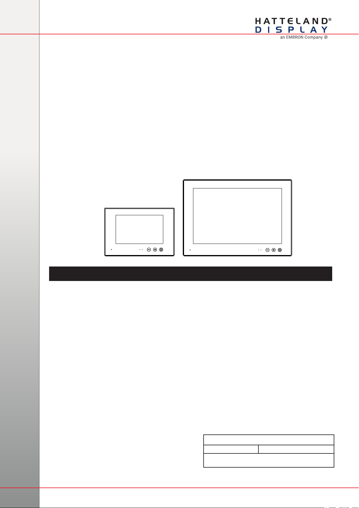
Maritime Multi Computer (MMC) - Introduction
Series X Displays and Panel Computers offer the ultimate in performance,
convenience, state of the art design and enduring quality for system integrators and
boat builders. Series X products offer a range of feature sets optimized for varying
requirements and applications.
The Series X Panel Computer range is a flexible all in one monitor & PC solution,
designed and type approved for the professional marine segment, where reliability
and long life time are key-pre requisites for the industry. The product range combines
state of the art display and computer technology with innovative features and options,
making it all that the integrator needs for top class type-approved marine systems.
The high performance MMC Panel Computer models provide a wide choice
of display size and format, along with various processor and storage options.
The compact, all-in-one MMC solution is the ideal one for all ship navigation or
automation installations. This range with all it’s versitility and capability provides a
robust and cost effective platform from which to run multiple applications and display
and manage data.
This model is delivered with a factory mounted Projected Capacitive Touch Screen
(Multitouch, USB interface) as standard. Brightness is dimmable from 0-100%.
A computer and display, all in one...
- MULTITOUCH
- Type Approved
- IP22 rear / IP66 front
- Superior Bonding Technology
- Module based, tailor-made systems made easy!
- GLASS DISPLAY CONTROL™ (GDC), Solid State Menu System
10
IND100110-12
Touchscreen
Introduction to products with touch screen
Nearly all of our products with touch screen use Projected Capacitive Touch screen (PCTS), widely used with great suc-
cess on mobile phones and typical pad devices. PCTS can be equally effective also for marine applications. One of the
advantages of PCTS is that it has features seen in both resistive and surface capacitive touch screen
technologies.
Multitouch is dened as the ability to recognize two or more simultaneous touch points. Using projected capacitive tech-
nology allows us to create a more intuitive form of human-device interaction. Touch interface gestures, supported by
projected capacitive sensors, can simplify the interface and provide an intuitive user experience that goes beyond the
typical "button replacement" found in most simple touch interfaces.
Please review the appropriate Product Datasheet (in this manual) to determine if PCTS are supported.
The technical benets of PCT are:
- Very good optical performance (same as surface capacitive)
- Environmentally strong, the touch sensor is inside the product (better than both surface capacitive and resistive)
- Supports Multitouch (Newer Operating System (OS) required in most cases.
- Excellent readability - light transmission of up to 91% through a standard sensor
- Stability - no drift, therefore no recalibration is required
- Pointing device - works with gloved and ungloved finger
- Resistance to contamination - by harsh cleaning fluids and other noxious substances
- Communicates via USB to external computer or internally
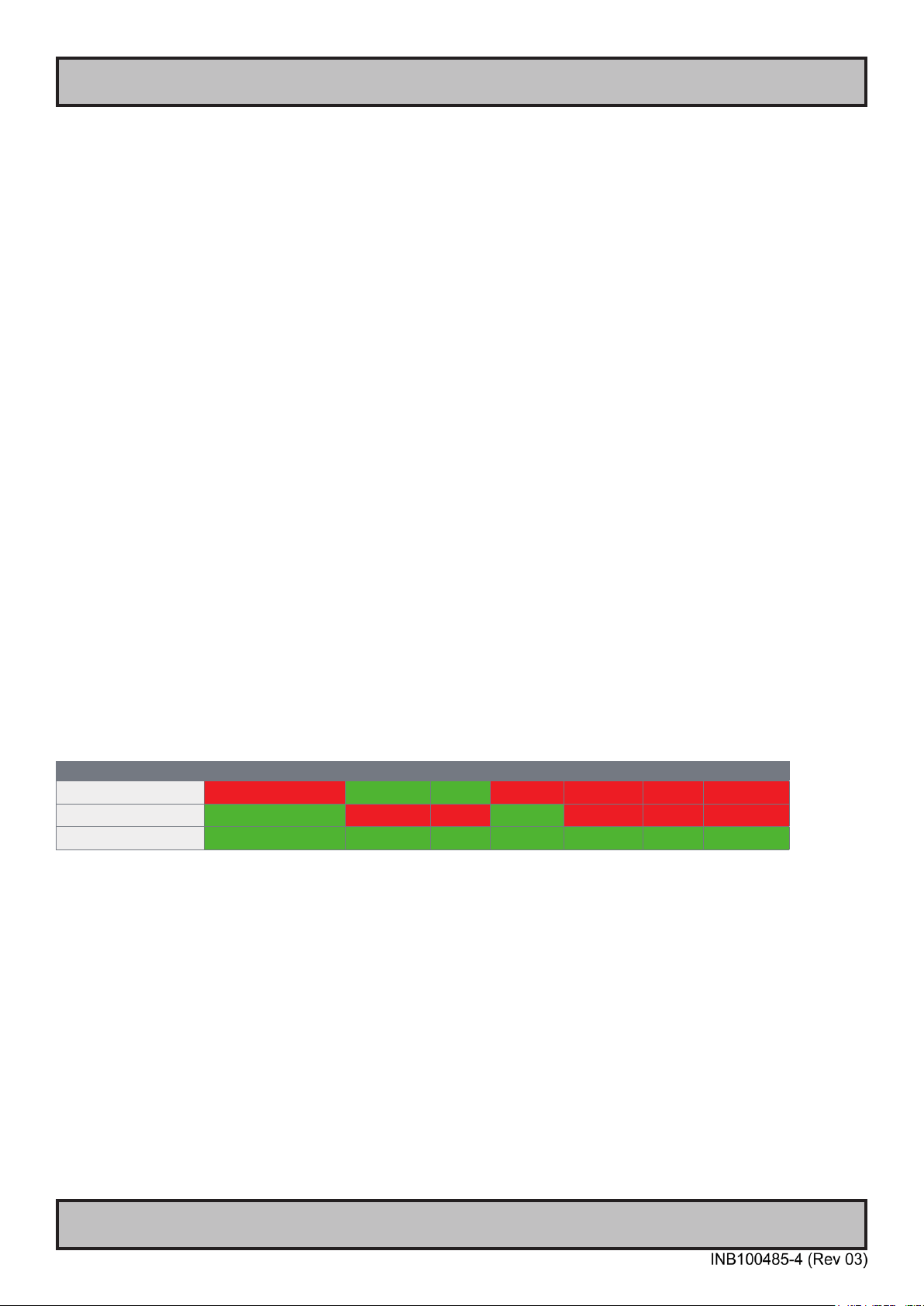
Comparisons between general Touch Technologies used by Hatteland Display:
Technology Optical Performance Gloves Water Durability Multitouch Stylus Objects
Analog Resisitive -- ++ ++ - - - --
Surface Capacitive ++ -- - + - - --
Projected Capacitive ++ + + *++ ++ ++ ++
*Projected Capacitive (PCTS) / Water: Touch Screen Glass Surface can withstand drip and direct rain, but expect reduced capability, detection and
performance if unit are exposed to these factors while powered. Hatteland Display recommends protecting the unit from direct rain or drips if critical
touch operations are to be performed. Take nessessary steps (if detected or suspected) within the installation environment to prevent accidental touch
gestures or presses not performed intentionally by a human operator.
Touch screen products

11Touch screen
IND100110-13
Touch Screen Drivers and Documentation
All units are shipped with a Documentation and Drivers DVD or CD which
contains suitable drivers*for touch screens. (Named MEDIA STD01).
You can also visit our website www.hatteland-display.com/archive to view the same
list (or even recently new added products) for our models with touch screen.
Before using the touch screen, it should be calibrated for your system.
Please install the 3rd party software*and use the Calibrate function.
For additional touch controller/screen documentation and updated drivers*, please
visit the 3rd party manufacturer website as found in the Touch Screen Wizard menu.
*General Note:
Newer Operating Systems (OS), from year 2011 and above, do not specically require additional 3rd party drivers in order to operate the touch
screen and support “Multitouch”. For example; Microsoft® Windows® 7 and above comes with default factory installed Windows HID drivers fully
supporting “Multitouch”. You may choose to install 3rd party drivers for example during trouble-shooting situations or to review features of the 3rd
party software. Hatteland Display suggests that you should use factory default Microsoft® Windows® 7 HID touch drivers in any case possible.
For older Operating Systems (like Microsoft® Windows® XP and older), before year 2011, the OS does not not support “Multitouch” technology and
the touch screen will just operate as a ordinary single-point touch screen. Additionally to get touch screen working at all in older OS, you need to
install 3rd party drivers.
Note that the lack of “Multitouch” support is not dependent on hardware or software/rmware for the controller specically, but rather dependent on
important core functions in the Operating System which are outside control of the 3rd party software.
Summary
Microsoft® Windows® 7 / Microsoft® Windows® 8 / Microsoft® Windows® 8.1 / Microsoft® Windows® 10 IoT
- All HD xxT21 / T22 / MVD units:
- Please use Windows® Generic HID driver, no specic driver needed to use multi-touch.
Microsoft® Windows® 7 32 bit only
- HD 07T22 / HD 13T22 units:
- Please use Windows® Generic HID driver, no specic driver needed to use multi-touch.
Linux (openSUSE® 11.4, Fedora™ 15, Ubuntu® 10.04 LTS, Ubuntu® 12.04 LTS)
- All units:
- Please use Linux Generic Touch driver.
Note: Kernel before 2.6.38: Single touch support.
Note: Kernel above 2.6.38: Multi touch support.
*32bit only available for HD 07T22 / HD 13T22 units. Other units, 32/64 bit supported.
------------------------------------------------- Note: Windows® XP is End Of Life ----------------------------------------------------------
Reference: http://www.hatteland-display.com/mails/09_2016_eol.html
Microsoft® Windows® XP
- 24 and 26 inch HD xx21 units:
- Please use Touch Screen Driver Wizard and install PCT Touch Utility, example PtouchUtility-1.0.0.4-150326.exe.
Reference August 2015: http://www.hatteland-display.com/mails/21_2015_ecn.html
Microsoft® Windows® XP
- 8, 12, 13, 15, 17 and 19 inch HD xxT21 units:
- Please use Touch Screen Driver Wizard and install eGalaxTouch Drivers (XPE_5.11.0.9223).
------------------------------------------------- Note: Windows® XP is End Of Life ----------------------------------------------------------
Touch screen products
12
IND100077-147
Product Labeling
Introduction
This section details the locations, content details and specications for factory mounted labels for all currently
available standard Hatteland Display Panel Computer (MMC) models. This information will in most cases also apply
for most Customized Models as well, but may differ based on customer requirements, in that case, please refer to the
customized User Manual (paper or electronic version, dependent on customer requirements).
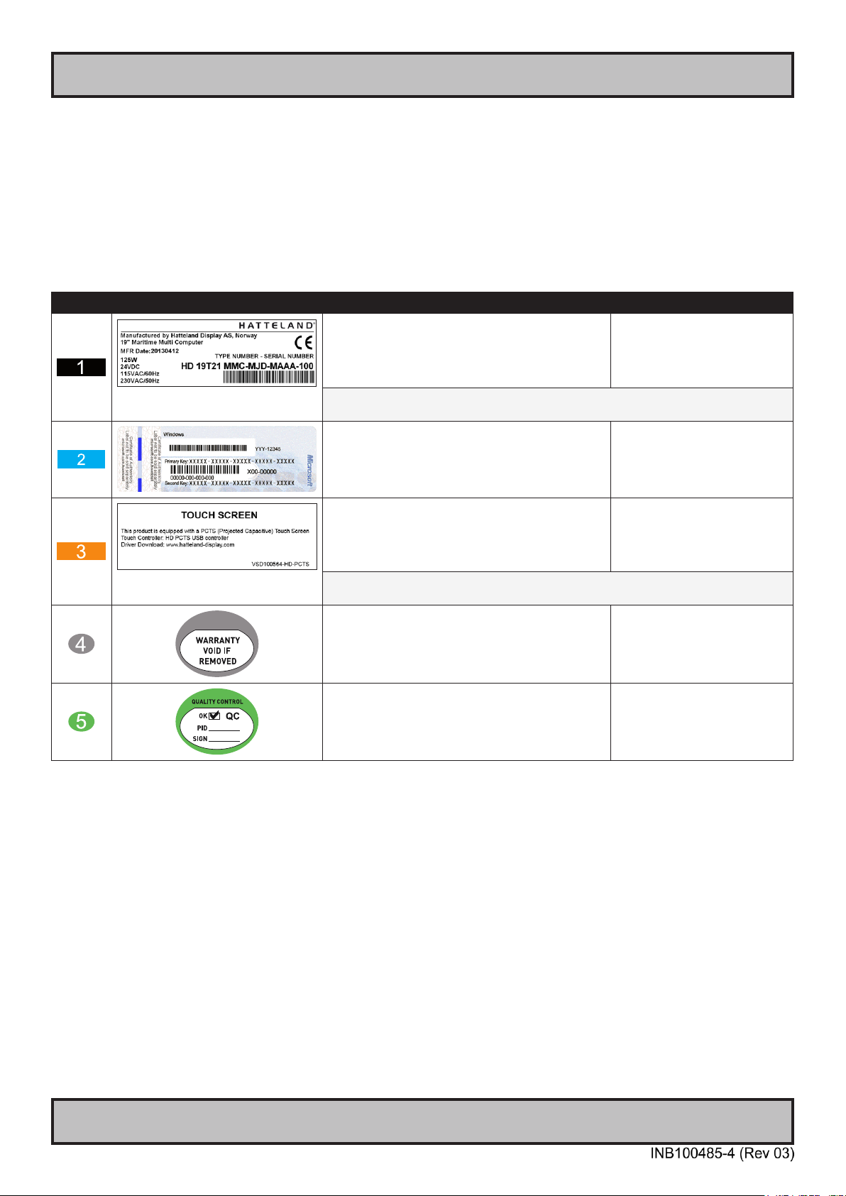
Label Size and Types
ID Label Layout Description Specication
Type : Serial Number Label
Name : Label B
Size : 60mm wide x 20mm high (rectangle size)
Note: Text content of label will match specications
derived from Data Sheet.
Silver with glue on back, non-
tearable and made for thermal
transfer printing.
Barcode type: CODE128 (used extensively world wide in shipping and packaging
industries. The symbology was formerly dened as ISO/IEC 15417:2007.)
Type : Operating System (OS) label.
Microsoft® Windows® Embedded Enterprise only.
Size : 70mm wide x 28mm high (rectangle size)
Note: Label only present if OS was part of factory
option order. Linux OS does not have any label.
As per delivered from supplier.
Type : Touch Screen Label
Name : Label B
Size : 60mm wide x 20mm high (rectangle size)
Note: Only present if Touch Screen was part of factory
option order.
Silver with glue on back, non-
tearable and made for thermal
transfer printing.
Note: Content on label will vary based on Touch Screen type and/or Touch Screen
Controller. Label shown to the right is for illustration purposes only!
Type : Warranty Label
Size : 30mm wide x 23mm high (oval size)
Tamper-proof sticker with glue on
back.
Type : Quality Control (QC) Label
Size : 30mm wide x 23mm high (oval size)
Ordinary sticker with glue on
back.

13
Product Labeling
IND100077-147
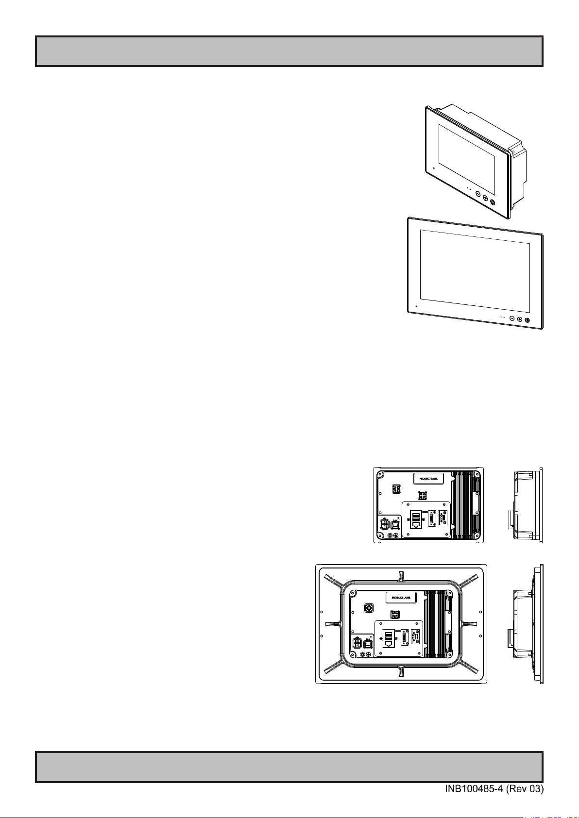
Label Locations
Number ID and coloring based on “Label Size and Types“ table from previous page. All illustrations below are seen
from rear (and side where needed) with connectors facing down. Actual labels regarding its size and text orientation
vs product size is drawn in. Due to space restrictions on selected units, some labels will be rotated 90 degrees to t
properly. The arrangement of labels may be shifted/stacked differently as it is based on factory options, such as; Touch
Screen and Operating System (OS), but they will be grouped together where possible.
Label Positions Notes Applies for Product Range
Labels placed on rear and
both sides.
HD 07T22 MMC-xxx-xxxx
Warranty label covers both
screw and bends over edge
(rear/side). Labels placed on
rear and side.
HD 08T21 MMC-xxx-xxxx
Warranty label bends over
edges (rear/side). Labels
placed on rear and both sides.
HD 13T22 MMC-xxx-xxxx
Warranty label covers screw.
Labels placed on rear and
side.
HD 13T21 MMC-xxx-xxxx
Intel® Core™2 Duo CPU
Warranty label covers screw.
Labels placed on rear and
side.
HD 13T21 MMC-xxx-xxxx
Intel® Atom™ CPU

14
IND100077-113
General
Product Labeling
Warranty Label
If you are to perform service on a unit still under warranty, any warranty will be void if this label show signs of removal
attempts (re-gluing) or removed completely. This label is located on the back of the product and covers a key screw.
This is to aid service departments in determining if there has been any unauthorized service on a unit still under
warranty.
Quality Control (QC) Label
This label indicates that the unit is produced, tested and packed according to the manufacture’s QA specications. It
will include a Personal ID and signature by the personnell responsible for approving the unit in production, test and
warehouse departments.

15
Installation

16Installation
IND100078-29
General Installation Recommendations
First Things First!
Applies for non-bonded product only: If exposed to humidity
in combination with temperature variations, product might
show condensation on the glass (inside and outside).
Inside condensation can be removed by power on the
product and set brightness to 100%. During minutes the
internal temperature rise will remove condensation.
Humidity Exposure Notice!
y
y
ATTENTION!
IND100148-5 - Rev 05
To prevent damage to
chassis and glass, please
review the illustrations ! Place horizontally on a smooth and clean surface (table with cloth) Do not stress the corners, nor place it on a coarse and/or dirty surface
CORRECT HANDLING! WRONG HANDLING!
CORRECT HANDLING! WRONG HANDLING!
Installation and mounting
1. Most of our products are intended for various methods of installation or mounting (panel mounting, bracket
mounting, ceiling/wall, console mounting etc.); for details, please see the relevant mechanical drawings.
2. Adequate ventilation is a necessary prerequisite for the life of the product. The air inlet and outlet openings must
denitely be kept clear; coverings which restrict ventilation are not permissible.
3. Generally, do not install the unit in a horizontal position (laying down), as this will cause heat to build up inside the
unit which will damage the LCD Panel. To prevent this problem we recommend installing the unit in a vertical
position (±30 degrees) to improve the airow through the unit.
4. To further improve the thermal situation we recommend to use forced air passing by the product. In some cases,
convection based cooling can create “heat zones” around the product. This may be required in high temperature
applications and also when there is reason to expect temperature problems due to non-optimal way of mounting.
5. Exposure to extreme direct sunlight can cause a considerable increase in the temperature of the unit, and might
under certain circumstances lead to overtemperature. This point should already be taken into consideration when
the bridge equipment is being planned (sun shades, distance from the windows, ventilation, etc.). To maximize
product life, it is recommended to use Hatteland Display's Sun Covers when the product is not in use. Long term
direct sun exposure might have cosmetic impacts on the product.
6. Space necessary for ventilation, for cable inlets, for the operating procedures and for maintenance, must be
provided.
7. If the push buttons of the product are not illuminated, an external, dimmable illumination (IEC 60945 Ed. 4, 4.2.2.3,
e.g. Goose neck light) is required for navigational use. The illumination shall be free from glare and adjustable to
extinction.
8. Information about necessary pull-relievers for cables is indicated in the Physical Connection section of this manual.
Attention must be paid to this information so that cable breaks will not occur, e.g. during service work.

17
General Installation Recommendations
Installation
IND100078-29
9. Do not paint the product. The surface treatment inuences the excess heat transfer. Painting, labels or other
surface treatments that differ from the factory default, might cause overheating.
10. Expose to heavy vibration and acoustic noise might under certain circumstances affect functionality and expected
lifetime. This must be considered during system assembly and installation. Mounting position must be carefully
selected to avoid any exposure of amplied vibration.
Installation limitations
Due to environmental factors, please review the points noted below.
A: Overheat prevention:
For Maritime Multi Computer (MMC, Panel Computers) it is advised that you do not mount the unit in a
vertical angle lower than ±30 degrees, as noted in point 3 (previous section), i.e. at mounting of the unit.
This is to prevent both overheating the unit as well as ensure proper cooling airow to sustain long-life and
stable operation. Panel Computer units generate more heat than regular Display units naturally because of
CPU and mainboard chips.
It should be noted that 24” and 26” MMC units have internal fans providing additional cooling airow of
their own, whilst smaller units (typically 8” to 19”) has no internal fans. In such cases, the ±30 vertical angle
may in certain situations allow for lower angle mounting provided that the console casing has adequate
cooling (see point D), however this is suggested as a trouble-shooting tip during installation or during short-
term observer use if found suitable. It should not be considered as a dentive trusted solution.
B: Glass Display Control™ (GDC) front glass touch buttons:
As this uses Projected Capacitive technology (instead of conventional hard physical buttons and knobs),
the touch controller can react and is sensitive to raindrops (for outdoor installations). To ensure that
raindrops do not stay on the unit’s at glass surface, please do not mount the unit in a vertical angle lower
than ±30 degrees, i.e. at mounting of the unit. This is to prevent accidental touches that are similar to a
human nger (cover area for a x period of seconds) as well as make sure the raindrops are “moving” and
runs down off the glass surface.
For Maritime Multi Display (MMD) and Industrial Standard Display (STD) units (not available for Panel
Computers (MMC) units), the angle could potentionally be lower as the On Screen Display (OSD) menu offers
a "OSD Key utdoor" function with 5 seconds delay before activation on front glass functions. Please review
the "OSD Menu Functions" to learn more. In certain situations this might help, but is only suggested as a
trouble-shooting tip during installation or during short-term observer use if found suitable. It should not be
considered as a dentive trusted solution.
C: Projected Capacitive Technology (PCTouch) MULTITOUCH and in general Touch Screen glass:
For all units with a factory mounted touch screen and for outdoor use especially, please review point B above
regarding standing raindrops. Only solution to this situation is not to mount the unit in a vertical angle lower
than ±30 degrees, i.e. at mounting of the unit to ensure touch screen is not activated and accidentally
automatically chooses functions in your running chart, radar or other software installed.
D: General rule for console mounted units:
To ensure proper cooling airow, long-life and stable operation for all units, please make sure that the
console casing has either fans or decent ventilation holes to prevent overheating inside the console due to
the combined temperature of both Display or Panel Computer units together with other electronic instruments.
A general rule is to make sure the console casing is capable of expelling “worst case scenario” in respect of
the “Max Power Consumption” of all devices installed. Please review also point 2, 5, 6 and 9 (previous
section) for additional information and installation tips.
Note that 24” and 26” Panel Computer units have their own internal fans. See point A for more information.

18
General Installation Recommendations
Installation
IND100078-29
General mounting instructions
1. The useful life of the components of all Electronics Units generally decreases with increasing ambient temperature;
it is therefore advisable to install such units in air-conditioned rooms. If there are no such facilities these rooms
must at least be dry, adequately ventilated and kept at a suitable temperature in order to prevent the formation of
condensation inside the display unit.
2. With most Electronic Units, cooling takes place via the surface of the casing. The cooling must not be impaired by
partial covering of the unit or by installation of the unit in a conned cabinet.
3. In the area of the wheel house, the distance of each electronics unit from the magnetic standard compass or the
magnetic steering compass must not be less than the permitted magnetic protection distance. This distance is
measured from the centre of the magnetic system of the compass to the nearest point on the corresponding unit
concerned.
4. Units which are to be used on the bridge wing must be installed inside the “wing control console” protected against
the weather. In order to avoid misting of the viewing screen, a 25 ... 50 W console-heating (power depending on the
volume) is recommended.
5. When selecting the site of a display unit, the maximum cable lengths have to be considered.
6. When a product is being installed, the surface base or bulkhead must be checked to ensure that it is at in order to
avoid twisting of the unit when the xing screws are tightened, because such twisting would impair mechanical
functions. Any unevenness should be compensated for by means of spacing-washers.
7. This Product shall be grounded to protective Earth. For AC Power cables this is done through the ground wire in the
connector, for DC input the ground bolt shall be used. A shorter and thicker cable gives better grounding. A 6mm²
is recommended, but a 4mm² or even 2.5mm² can be used for this purpose
8. Transportation damage, even if apparently insignicant at rst glance, must immediately be examined and be
reported to the freight carrier. The moment of setting-to-work of the equipment is too late, not only for reporting the
damage but also for the supply of replacements.
9. The classication is only valid for approved mounting brackets provided by Hatteland Display. The unit shall be
mounted stand-alone without any devices or loose parts placed at or nearby the unit. Any other type of mounting
might require test and re-classication.

19
General Installation Recommendations
Installation
IND100078-29
Ergonomics
1. The front surface of the display glass has an anti-reective (AR) coating which can be scratched and damaged with
improper cleaning. It is recommended to use only 90+% pure Isopropyl alcohol (Isopropanol) and a soft fabric
cloth for this rst cleaning. Fold a cloth into a small pad, dampen the cloth with alcohol, and wipe the glass from
one edge to the other in one direction with one continuous motion. The product glass will require cleaning as
needed. The soft cloth & alcohol wipe is recommended to clean ngerprints and oils off the glass. Water stains
(including coffee, tea & coke) should be rst cleaned off the glass with a soft fabric cloth wet with water,
immediately followed with wiping using an alcohol wetted cloth.
2. Adjust the unit height so that the top of the screen is at or below eye level. Your eyes should look slightly
downwards when viewing the middle of the screen.
3. Adjust screen inclination to allow the angle of gaze to remain at the centre of the screen approximately
perpendicular to the line of gaze.
4. When products are to be operated both from a sitting position and from a standing position, a screen inclination of
about 30° to 40° (from a vertical plane) has turned out to be favourable.
5. The brightness of displays is limited. Sunlight passing directly through the bridge windows - or its reection - which
falls upon the screen workplaces must be reduced by suitable means (negatively inclined window surfaces,
venetian blinds, distance from the windows, dark colouring of the deckhead). However, units can be offered with
optical enhanced technology and/or High Bright panels to reduce reections and are viewable in direct sun light,
but as a general rule the units at the bridge wing area are recommended to be installed or mounted by suitable
alignment or bulkhead / deckhead mounting in such a way that reections of light from the front pane of the display
are not directed into the observer’s viewing direction.
6. The use of ordinary commercial lter plates or lter lms is not permitted for items of equipment that require
approval (by optical effects, “aids” of that kind can suppress small radar targets, for example).
7. For ECDIS applications, the minimum recommended viewing distance are as follows:
(IEC62288, Part 7.5 Screen resolution)
17 inch = 907mm 19 inch = 1010mm 24 inch = 951mm 26 inch = 985mm
Cables
Use only high quality shielded signal cables.
Cable Entries & Connectors (Marked area)
Illustration below for smallest/largest sizes only.
Bottom View Back View

20
General Installation Recommendations
Installation
IND100078-29
Maximum Cable Length
Any cable should generally be kept as short as possible to provide a high quality input/output. The maximum signal
cable length will depend not only on the signal resolution and frequency, but also on the quality of the signal output from
the computer/radar.
This manual suits for next models
5
Table of contents
Other EMBRON Marine Equipment manuals


