EMC-PARTNER AVI3000 User manual

LARGEST RANGE OF IMPULSE TESTERS UP TO 100KV/100KA
User Manual
Version 1.0
AVI3000
•CN-BT7
•SHUNT0E1
•CN-GI-CI-V

The Manufacturer
EMC PARTNER AG
Baselstrasse 160
4242 Laufen
Switzerland
Phone +41 61 775 20 30
Fax +41 775 20 59
service@emc-partner.ch
Your local representative
Check www.emc-partner.ch to find your local representative
The small print
All products from EMC PARTNER AG fulfill the EMC and safety requirements to obtain
CE certification. A copy of the individual certificates can be viewed and downloaded from
www.emc-partner.com section company documents.
This document may only be reproduced or distributed as the complete document. Partial repro-
duction of this document requires full, written approval of EMC PARTNER.
generated on June 29, 2016 with opensource software L
A
T
EX
Subject to change without notice.
Page 2/45

Safety instructions
This warning sign is visible on the tester. Meaning: This equipment should only be operated
by trained personnel after carefully reading the user manual.
The system belongs to Safety class 1
The system fulfills the requirements of the safety standards IEC 61010 for laboratory measurements
equipment "Safety requirements for electrical measuring, control and laboratory equipment".
Consider always the following safety points
•Dangerous mains voltage or high voltages are present inside the test equipment and ALL devices
attached to it.
•The protective Earth must be connected to Earth on the test equipment.
•Before removing any covers from the test equipment, remove all external connection cables.
•Before changing the mains fuse, remove all external connection cables.
•Fuses should only be replaced with the same type and value.
•People with heart pacemakers must not be in the vicinity of the test equipment when it is in
operation.
•Do not switch on or operate the test equipment if an explosion hazard exists.
•The test equipment should be operated in a dry room. If condensation is visible, the affected
unit(s) should be dried before operating.
•Never touch the Equipment under Test (EUT), when the test system is operating.
•Establish a safety barrier around the EUT and if required connect it to the safety circuit in the
auxiliary connector on the rear panel. The cables under high voltage must not be touched during
testing.
•The EUT should be covered and/or well marked during the tests.
•If protective elements, which are tested are likely to explode during tests they must be covered
with a protective cabinet.
•If the test equipment or any of the system components are damaged or it is possible that damage
has occurred, for example during transportation, do not apply any voltage.
•This user manual is an integral part of the Test-System. EMC PARTNER and its sales partners
refuse to accept any responsibility for consequential or direct damage to persons and/or goods due
to none-observance of instructions contained herein or due to incorrect use of the test equipment
Typographical Conventions
Warnings
Safety notices that must be heeded are indicated with this warning triangle.
additional advice
Throughout the user manual very important or helpful advice is indicated with this symbol.
Page 3/45

Sicherheitshinweise
Gefahr! Dieses Warnsysmbol ist am Tester sichtbar angebracht. Es bedeutet: Diese Ausrüstung
darf nur durch ausgebildetes Personal bedient werden, nachdem diese die Bedienungsanleitung
sorgfältig gelesen hat.
Das Gerät gehört der Schutzklasse I an.
Das Gerät erfüllt die Anforderungen der Sicherheitsnormen IEC 61010 für Messungen in Laboratorien
“Sicherheitsanforderungen an elektrische Mess- und Regelgeräte sowie Laborausrüstung”.
Beachten Sie stets die folgenden Sicherheitshinweise:
•Gefährliche Netzspannung oder Hochspannung liegt im Inneren der Testausrüstung und an ALLEN
daran angeschlossenen Geräten an.
•Der Schutzerdeanschluss der Testausrüstung muss mit der Schutzerde des Netzes verbunden sein.
•Bevor Sie irgendwelche Abdeckungen von der Testausrüstung entfernen, entfernen Sie alle äusseren
Anschlusskabel.
•Bevor Sie die Netzsicherung austauschen, entfernen Sie alle äusseren Anschlusskabel.
•Netzsicherung nur mit demselben Typ und Ansprechwert ersetzen.
•Personen mit Herzschrittmacher dürfen sich nicht in der Nähe des Geräts aufhalten, wenn dieses
in Betrieb ist.
•Schalten Sie die Testausrüstung nicht ein oder betreiben Sie das Gerät nicht, wenn Explosionsgefahr
besteht.
•Die Testausrüstung darf nur in einem trockenen Raum betrieben werden. Wenn Kondensation
(Beschlag) sichtbar ist, sind die betroffenen Teile der Ausrüstung zu trocknen.
•Berühren Sie niemals die getestete Ausrüstung (EUT), wenn das Testsystem arbeitet.
•Stellen Sie eine Sicherheitsabtrennung rund um das EUT auf und verbinden Sie diese, wenn verlangt,
mit dem Sicherheitskreis im Hilfsanschluss (Auxiliary) an der Rückwand. Die unter Hochspannung
stehenden Kabel dürfen während des Tests nicht berührt werden.
•Während des Tests sollte das EUT abgedeckt und/ oder gut markiert werden.
•Wenn Schutzelemente leicht explodieren können während Tests, müssen diese mit einem schützen-
den Deckel abgedeckt werden.
•Legen sie keine Spannung an, wenn die Testeinrichtung oder irgendwelche Systembestandteile
beschädigt sind oder möglicherweise ein Schaden eingetreten ist, zum Beispiel beim Transport.
•Diese Bedienungsanleitung ist ein vollständiger Bestandteil des Testsystems. EMC PARTNER und
seine Verkaufspartner lehnen jede Verantwortung für direkte wie für Folgeschäden an Personen oder
Gütern ab, die aufgrund von Nichtbeachten von hierin enthaltenen Anweisungen oder aufgrund von
unrichtigem Gebrauch dieser Testausrüstung entstehen.
Typografische Übereinkünfte
Warnung
Sicherheitshinweise, die befolgt werden müssen, sind mit diesem Warndreieck gekennzeichnet
Zusätzlicher Hinweis
Überall in der Bedienungsanleitung wird ein sehr wichtiger oder hilfreicher Hinweis mit diesem
Symbol gekennzeichnet.
Page 4/45

Consignes de sécurité
Ce sigle d’avertissement est visible sur le testeur. Signification: Cet équipement ne doit être
utilisé que par du personnel formé et après avoir soigneusement lu le mode d’emploi.
Le système appartient à la classe de sécurité 1
Le système répond aux exigences des normes de sécurité CEI 61010 pour les équipements de labora-
toire "Exigences de sécurité pour les appareils électriques de mesure, de contrôle et d’équipement de
laboratoire".
Considérez toujours les points de sécurité suivants:
•Des tensions secteurs dangereuses ou des tensions élevées sont présentes à l’intérieur de l’équipement
de test et de TOUS les périphériques.
•La mise à la terre de l’équipement de test doit être effectuée.
•Avant de retirer les couvercles de l’équipement, débranchez tous les câbles de connexion externes.
•Avant de changer le fusible secteur, débranchez tous les câbles de connexion externes.
•Les fusibles ne doivent être remplacés que par le même type et valeur.
•Les personnes portant un stimulateur cardiaque ne doivent pas se tenir à proximité de l’équipement
de test lorsqu’il est sous tension d’opération.
•Ne pas allumer ou faire fonctionner l’équipement de test si un risque d’explosion existe.
•L’équipement de test doit être utilisé dans un local sec. Si de la condensation est visible, les
appareils affectés doivent être séchés avant utilisation.
•Ne jamais toucher l’équipement sous test (EST), lorsque le système est sous fonction.
•Mettre en place une barrière de sécurité autour de l’EST et, si nécessaire raccorder la au circuit de
sécurité du connecteur auxiliaire sur le panneau arrière. Les câbles sous haute tension ne doivent
pas être touchées pendant le test.
•L’EST doit être couvert et / ou bien marqué pendant les essais.
•Si des éléments de protection sont susceptibles dŠexploser lors de tests, ils doivent être couverts
avec un boîtier de protection.
•Si l’équipement de test ou l’un des composants du système ont été endommagés ou il est possible
que des dommages ont eu lieu, par exemple pendant le transport, ne pas appliquer de tension.
•Ce manuel fait partie intégrante du Système de Test. EMC PARTNER et ses partenaires commerci-
aux refusent d’accepter toute responsabilité pour des dommages indirects ou directs à des personnes
et / ou des marchandises dues au non-respect des instructions contenues dans ce document ou en
raison d’une mauvaise utilisation de l’équipement de test.
Conventions Typographiques
Avertissements
Les consignes de sécurité qui doivent être respectées sont indiqués par ce triangle de signalisa-
tion.
Conseils supplémentaires
Tout au long du manuel d’utilisateur des conseils très important ou utile sont indiqués par ce
symbole
Page 5/45

Contents
Contents
1 System overview 8
2 Initial Operation 10
2.1 UnpackingandChecking .................................. 10
2.2 Installation.......................................... 10
2.3 PoweringtheEquipment................................... 10
2.4 SafetyCircuit ........................................ 10
3 Using the Generator 11
3.1 Frontpanel.......................................... 11
3.2 Rearpanel.......................................... 13
3.3 SoftwareUserInterface ................................... 14
4 Perform a test 16
4.1 Programmingthegenerator................................. 16
4.2 Runatest .......................................... 17
4.3 Pin Injection WF3 / WF4 / WF5A . . . . . . . . . . . . . . . . . . . . . . . . . . . . . 18
4.3.1 SystemCalibration.................................. 18
4.3.2 EUT-Test ...................................... 19
4.4 Cable Bundle WF1, WF2, WF3, WF5A, WF6 . . . . . . . . . . . . . . . . . . . . . . . 20
4.4.1 Calibration...................................... 20
4.4.2 EUT-Test ...................................... 21
4.5 GroundInjectionWF4.................................... 22
4.5.1 SystemCalibration.................................. 22
4.5.2 EUT-Test ...................................... 24
4.6 CableInductionWF4 .................................... 24
4.6.1 SystemCalibration.................................. 24
4.6.2 EUT-Test ...................................... 26
5 Additional Software Features 27
5.1 Protocols........................................... 27
5.2 Setuplibrary......................................... 27
5.2.1 Storesetup ..................................... 28
5.2.2 Loadsetups ..................................... 28
5.3 Setuplinker ......................................... 28
5.4 Filemanager......................................... 29
6 Configuration 30
6.1 Settings ........................................... 30
6.2 Generator .......................................... 31
7 Accessories 32
8 Remote Operation 33
8.1 TEMA3000 ......................................... 33
9 Maintenance and Service 34
9.1 Firmwareupdate....................................... 34
Page 6/45

Contents
9.2 Maintenance......................................... 34
9.3 Cleaning ........................................... 34
9.4 Warranty........................................... 34
9.5 CustomerService ...................................... 35
10 Technical Data 36
10.1Max.TestLevels ...................................... 36
10.2WF1CableInduction .................................... 37
10.3WF2CableInduction .................................... 37
10.4WF31MHzPinInjection .................................. 38
10.5WF31MHzCableInduction................................. 38
10.6 WF3 10MHz Cable Induction . . . . . . . . . . . . . . . . . . . . . . . . . . . . . . . . 39
10.7WF4PinInjection...................................... 39
10.8WF4GroundInjection.................................... 40
10.9WF4CableInjection..................................... 40
10.10WF5APinInjection ..................................... 41
10.11WF5ACableInduction ................................... 41
10.12WF6 ............................................. 42
10.13MultipleStrokeTiming ................................... 42
10.14MultipleBurstTiming.................................... 42
10.15AVI3000 ........................................... 43
10.16CN-BT7 ........................................... 43
10.17CN-GI-CI-V ......................................... 44
10.18SHUNT0E1 ......................................... 44
11 Appendix 45
11.1Recycling/Disposal..................................... 45
Page 7/45

1 System overview
1 System overview
AVI3000 (PN 107630)
AVI3000 generator is a compact system with all waveforms for DO-160 section 22 up to level
3 and MIL-STD-461 CS117 for internal tests. A coupling transformer, for cable injection tests,
completes the system. The 7 inch graphic colour touch panel provides an intuitive and comfortable
user interface. Interactive parameter input, help text and graphic illustrations, guide the user
through the instrument programming process.
CN-BT7 (PN 107632)
Coupling transformer for Cable Bundle testing used with WF1, WF2, WF3, WF5A, WF6. The
CN-BT7 has a large aperture of 6 x 9cm and is equipped with a monitor loop for calibration and
supervision during the test.
SHUNT0E1 (PN 103575)
0.1 Ohm shunt with SHV-BNC connector for direct measurement of current impulses on AVI3000
and CN-BT7.
CN-GI-CI-V (PN 103577)
Page 8/45

1 System overview
The preferred coupling method for WF4 is Ground Injection. Ground Injection is possible directly
with AVI3000 without any additional coupling device. The CN-GI-CI-V is only neccessary if WF4
will be applied as Cable Induction test.
Not all accessories are used for all tests. The chapter “Perform a test” provides more informa-
tion.
Page 9/45
2 Initial Operation
2 Initial Operation
2.1 Unpacking and Checking
1. Check the packaging for signs of damage. If damage is visible, report this to the shipping company
immediately.
2. Gently remove the equipment from the packaging.
3. Check the delivery for completeness using the delivery note and the accessory lists for the var-
ious items. If something is missing, contact EMC PARTNER or your local sales representative
immediately.
4. Check the equipment for any damage. If there is damage, immediately contact the shipping
company who made the delivery.
Retain the original packing material for a safe transport at a later date.
2.2 Installation
The equipment is designed for use under laboratory conditions. Make sure that all fan openings are
unobstructed, that the airflow perforations are unimpeded, and that the minimum distance from the wall
is 10cm. An insufficient airflow can cause the equipment to overheat, which may disturb the operation
and even cause damage.
Most equipment from EMC PARTNER can be mounted in a 19" Rack. A special rack mounting
kit is available. Contact your local sales company for a quotation.
2.3 Powering the Equipment
Check that the local AC-supply is suitable for the equipment. Power rating of the instrument is indicated
on the type plate next to the AC power supply connector located on the rear panel. Only use the supplied
power cord to connect to your public power supply.
The equipment must always be connected to protective earth. Check the earth connection on
your power outlet before you connect and turn on the equipment.
2.4 Safety Circuit
The Generator is equipped with a Safety Circuit. As long as the safety circuit is open, no test can be
started. To close the safety circuit
1. connect the auxiliary Connector on the rear panel
2. pull out the emergency stop button on the front panel with a slight turn clockwise
A closed safety circuit is indicated by a red illuminated emergency stop button
Page 10/45

3 Using the Generator
3 Using the Generator
3.1 Front panel
1
2
3
4 5
6 7 8
9
1 ON/STBY
Power-up or power-down the generator.
2 Touchscreen monitor
User interface to perform all functions including test types selection, parameter entry, saving and
recalling tests.
3 Rotary knob
Entry device enables faster navigation and parameter entry.
4 Run/Stop
Starts or stops the selected test.
A green blinking LED indicates a running test.
A red blinking LED indicates a stopped test due to an error.
A red LED indicates a finished test.
Page 11/45

3 Using the Generator
5 Emergency stop button
Push to open the safety circuit.
As soon as the safety circuit is open, all running tests are immediately stopped and no more tests
can be started.
Release the emergency stop button with a slight turn clockwise.
A closed safety circuit is indicated by a red illuminated emergency stop button.
6 USB Port
Connect a USB memory stick to copy files (setups, protocols, error logs) from the generator. The
USB interface is also used to update the internal firmware.
7 Auxiliary Connection
Interface for additional external equipment.
8 Trigger out
BNC output for a direct connection to the scope to start pulse acquisition. Level and duration
depend on the specific test. Some typical values are
•12V primary impulse trigger
•8V secondary impulse trigger
•5V EUT power state
9 Plug-in module
The plug-in contains all WF3 circuits. It is part of the AVI3000 standard delivery. Future plug-ins
could be developed for different wave forms. The plug-ins are secured by two retained screws on
the bottom.
Never remove a plug-in during a running test.
Page 12/45
3 Using the Generator
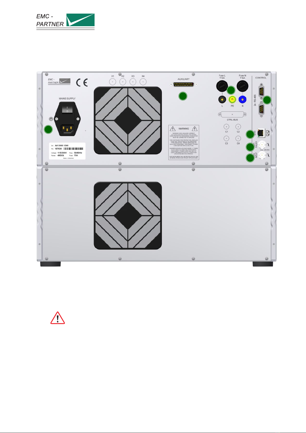
3.2 Rear panel
1
23
4
5
6
7
1 AC Socket / Main fuse
A country specific mains cable is delivered with the equipment, this should be used to connect to
the mains power supply. A mains fuse is located in the socket housing. The value is indicated on
the equipment type plate.
Take care to ensure the power main matches the power ratings on the equipment type
plate.
The generator must always be connected to protective earth
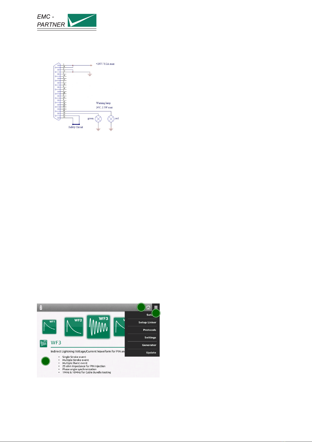
2 Auxiliary connector
Fit the auxiliary connector delivered with the equipment, to close the safety circuit.
It is possible to extend the safety circuit or to connect additional external warning lamps.
Page 13/45
3 Using the Generator
•The green lamp indicates safety circuit open, no test can be started
•The red lamp indicates safety circuit closed, tests can be started
3 EUT Power Input
Separate EUT Power input if required for a specific plug-in.
4 RS485 Interfaces
Interfaces to connect additional equipment that is controlled directly from the test equipment.
5 Ethernet Interface
Remote control using TEMA3000 software via a common Ethernet interface.
6 EUT Failed
A falling edge to ground impressed on the BNC connector is indicated in the test protocol as an
EUT Fail condition. The input is internally pulled up to max. 24V. Driving with an open-collector
output is recommended.
7 Trigger Input
A falling edge to ground on the BNC connector, triggers impulse release. This function must be
configured in the test parameter menu. The input is internal pulled up to max. 24V. Driving with
an open-collector output is recommended.
3.3 Software User Interface
1
23
1 Test selection
The main window is a carousel of all tests available in the equipment. A short description is
included with each test type. A green icon indicates test is available, a grey icon indicates test
Page 14/45

3 Using the Generator
is not currently available. Select a test by bringing the relevant icon to centre screen. This is
achieved by finger swipe on the touch panel or by using the rotary knob.
Not all tests are available all the time. Availability depends on hardware configuration.
To simplify the menu structure, tests that are unavailable can be removed from the
configuration.
≡(General Menu) –> Settings –> Test Settings
2 Home button
Select from any point in the menu structure to return to main window.
3 General menu
Activates a drop-down menu on the right side giving access to equipment configuration settings.
Page 15/45

4 Perform a test
4 Perform a test
Additional information for calibration is also available in the calibration report.
4.1 Programming the generator
The same process is used to program the generator for different tests. In the first step, the parameters
should be set according to the requirement of the test.
1
2
3
1 Main category
For quick access, categories at the bottom of the display contain groups of relevant parameters.
Select a category using the touch panel.
2 Parameter list
All parameters from a selected category are shown on a single screen. Click on a parameter to edit
the value.
Press and turn the rotary knob at the same time for a quick parameter change.
All parameters are checked for validity during the entry process. If necessary (for example test
level too high), the system automatically corrects the value. Corrected values are indicated by a
red background.
The system also checks for inconsistencies with other parameters and, where necessary, makes an
adjustment. It is not possible to create a test containing invalid parameters.
Page 16/45

4 Perform a test
For each parameter, an additional help text ist provided directly on the generator. Press and hold
a parameter to open the help text in a popup window.
3 Parameter image
Individual images clarify the effect of each parameter.
4.2 Run a test
Starting a test by pressing the run button on the front panel, changes the display to the run view.
1
23 4
5
1 Information Area
Indicates the most important information about a running test.
2 Progress bar
Indicates progress of the whole test and, if available, about the current cycle.
3 Status bar
Provides information about the current event.
4 Running options
Click to open a menu where it is possible to mark or fail a test at the current position. This
information will be included in the protocol.
5 Parameter change
Click to open a shutter menu containing all parameters that can be edited while a test is running.
Depending on the test type, parameter change will take place with the next cycle or after a few
seconds. Changed values are highlighted for a few seconds in the information area.
Page 17/45

4 Perform a test
4.3 Pin Injection WF3 / WF4 / WF5A
4.3.1 System Calibration
Prior to each test, the system has to be calibrated. The calibration is made using the 2m cable on the
AVI3000 at the desired test level with both polarities.
1
2
3
4
1 Generator
Select the desired Waveform and Pin Injection as coupling type.
For all Pin Tests, the necessary decoupling elements are already built into the generator.
2 Connection cable
The calibration is performed including a 2m MC-cable. Connect the cable to the correct output.
The pictures shows the setup for WF4 and WF5A. For WF3, the output is on the front
of the plugin. The correct output is always indicated by a red LED.
3 Measurement Equipment
Use a HV differential probe to measure the open circuit voltage. The current is measured with a
current probe with a short circuit at the end of the connection cable. It may be necessary to adjust
the generator output to achieve the required test level. Current measurements must be made at
the adjusted level to determine the generator impedance.
Page 18/45

4 Perform a test
4 Oscilloscope
The oscilloscope must have a minimum bandwith of 500 MHz.
4.3.2 EUT-Test
1
2
3
4
5
1 Generator
Select the desired Waveform and Pin Injection as coupling type. For all Pin Tests, the necessary
decoupling elements are already built into the generator.
2 Connection cable
The 2m MC-cable is connected between the EUT and the generator output.
The pictures shows the setup for WF4 and WF5A. For WF3, the output is on the front
of the plugin. The correct output is always indicated by a red LED.
3 Voltage monitor
Use a HV differential probe to monitor the voltage during the test.
4 Current monitor
Use a current probe to monitor the current during the test.
5 Oscilloscope
The oscilloscope must have a minimum bandwith of 500 MHz.
Page 19/45

4 Perform a test
4.4 Cable Bundle WF1, WF2, WF3, WF5A, WF6
4.4.1 Calibration
Prior to each test, the system has to be calibrated. The calibration is made at the desired test level with
both polarities.
1
2
3
4
1 Generator
Select the desired Waveform and Cable Induction. The correct output is always indicated with a
red LED.
The connection setup for SingleStroke, MultipleStroke and MultipleBurst is the same.
The desired mode has to be selected in the generator menu.
2 CN-BT7
The output of the generator is connected with the input of the CN-BT7. For the different wave-
forms, different setups are used.
•For WF1, connect the WF1-output on the generator with the CN-BT7 INPUT 1 using a 2 m
HV-BNC cable. On the coupler, put the MC-bridge in the FILTER position.
•For WF2, connect the WF2-output on the generator with the CN-BT7 INPUT 1 using a 2 m
HV-BNC cable. On the coupler, put the MC-bridge in the FILTER position.
•For WF3 1MHz, connect the WF3 1MHz-output on the generator with the CN-BT7 INPUT
1 using a 2 m HV-BNC cable. On the coupler, put the MC-bridge in the FILTER position.
•For WF3 10MHz, connect the WF3 10MHz-output on the generator with the CN-BT7 INPUT
1 using a 1 m HV-BNC cable. On the coupler, put the MC-bridge in the PARKING position.
•For WF5A, connect the WF5A-output on the generator with the CN-BT7 INPUT 2 using a
2 m MC cable. On the coupler, put the MC-bridge in the FILTER position.
Page 20/45
Table of contents
Other EMC-PARTNER Test Equipment manuals


Popular Test Equipment manuals by other brands


PIE
PIE PIECAL 334Plus operating instructions

Instron
Instron 3400 Series Operator's guide

Columbus McKinnon
Columbus McKinnon Yale RPYS-1215 Translated Operating Instructions

Ametek
Ametek Newage VERSITRON AT130-RDS Operation manual

Agilent Technologies
Agilent Technologies 41900A Operation and service manual

Markes International
Markes International Easy-VOC C-EZVOCPO Instructions for use


