EMC-PARTNER ESD3000 User manual

E-ESD3000-E-Manual.doc 1/66
User Manual ESD3000
Title: EMC Test System ESD3000
Date: 22.03.2002
Division Manager: M. Lutz
Quality Manager: R. Henz
Revised: 10.May 2016
EMC TESTER
Electrostatic Discharge ESD3000
ESD3000-System
2/66
ATTENTION
This user manual provides information necessary for operation of the test
equipment.
Throughout the users manual, standard references are used as an aid to
understanding only.
The relevant standard(s) must be obtained and used in conjunction with this
users manual
Declaration of Conformity
See sheets attached at the end of this user manual:
•Declaration of conformity to product standards
•Declaration of conformity to low voltage directive
•Declaration of conformity to EMC directive

ESD3000-System
3/66
Contents:
1 DESCRIPTION 7
1.1.1 Electrostatic discharge ESD 7
1.1.2 How ESD, EFT, SURGE, DIPS differ 7
1.2 Technical data of the ESD3000 and DM Discharge Modules 8
1.2.1 ESD3000 equipment 8
1.2.2 Discharge Module ESD3000DM1 (IEC 61000-4-2 and EN61000-4-2) 8
1.2.3 Discharge Module ESD3000DM2 (ISO TR10605 - inside vehicle, module tests) 9
1.2.4 Discharge Module ESD3000DM4 (MIL-STD-883E, MIL-STD-464, GR78-CORE) 9
1.2.5 Discharge Module ESD3000DM5 (RTCA/DO 160) 9
1.2.6 Discharge Module ESD3000DM6 (IEC 61340-3-1, JEDEC 22-A114, MIL-STD-750D9) 10
1.2.7 Discharge Module ESD3000DM7 (IEC 61340-3-2, JEDEC 22-A115) 10
1.2.8 Discharge Module ESD3000DM8 (IEC 60571, EN 50155) 10
1.3 Technical data of the ESD3000RM and DN Discharge Networks 11
1.3.1 Discharge Network ESD3000DN2 (ISO TR10605 - inside vehicle, module tests) 11
1.3.2 Discharge network ESD3000DN3 (ISO TR10605 -outside vehicle, sensitive classification) 11
1.3.3 Discharge Module ESD3000DN4 (MIL-STD-883E, MIL-STD-464, GR78-CORE) 12
1.3.4 Discharge Module ESD3000DN5 (MIL-DLT-23659D, STANAG 4239, MIL-STD 331) 12
1.3.5 Discharge Module ESD3000DN6 (MIL-DLT-23659D, STANAG 4239, MIL-STD 331) 12
1.4 Mechanical dimensions 13
1.5 Power Consumption 13
1.6 Accessories, dimensions 14
1.6.1 Included articles, dimensions 14
1.6.2 Standard accessories 14
2 SAFETY 15
2.1 Safety standard 15
2.2 Climatic Conditions 15
2.3 Precautionary measure during use 16
2.4 Electromagnetic Compatibility 16
2.5 The manual is an integral part of the equipment. Refer to the manual. 16
2.6 No operation of ESD3000 without ground wire 16
3 MECHANICAL STRUCTURE 17
3.1 General 17
3.2 Overview on ESD3000 system 17
3.2.1 ESD3000 Contact Discharge (CD) up to max. 10kV with Discharge Module (DM ) 17
3.2.2 ESD3000 Contact Discharge (CD) up to max. 30kV with (RM and (DM ) 17

ESD3000-System
4/66
3.2.3 Avoiding Mechanical Damage to Discharge Modules 18
4 CONTROL PANEL 19
4.1 Front panel of the ESD3000 19
4.2 Interchange of discharge modules 20
4.3 Interchange of the finger and tips 20
4.4 Inputs and Outputs 20
5 PREPARATION FOR OPERATION 21
5.1 Attention, Refer to Manual 21
5.1.1 ESD test set up 21
5.1.2 Test set-up for table top equipment 22
5.2 Practical testing sequence 23
6 TESTING WITH THE ESD3000 25
6.1 Contact discharge 25
6.2 Air discharge 26
6.3 Main parameter setting with the buttons on the front plate 27
6.4 The different software menus of the ESD3000 29
6.4.1 Repetition, number of pulses, count mode 29
6.4.2 Menu „Ramps“ 30
6.4.3 Menu „Setup“ 31
6.4.4 Menu „Settings“ 32
6.4.5 Menu „Service“ 32
6.4.6 Reset of the ESD3000 to default values 33
6.5 Parameter changing during operation „RUN Mode“ 33
7 MAINTENANCE AND SERVICING 35
7.1 Maintenance 35
7.2 Verification of the ESD3000 by the user 35
7.3 Verification of the ESD3000 by EMC PARTNER AG 35
7.4 System Reset 36
7.5 Caution with calibration labels 36
7.6 What must be done when the serial number is not indicated during the start up 36

ESD3000-System
5/66
8 WHAT MUST BE DONE FOLLOWING FAILED OPERATION 37
8.1 Display messages 37
8.1.1 Examples of messages 37
8.2 Service; Repairs 37
8.3 Spare parts list 37
8.4 Service department of EMC PARTNER AG 38
9 CHARGING THE BATTERIES OR REPLACING BATTERIES 39
10 PACKAGING AND TRANSPORT 41
10.1 Packaging 41
10.2 Transport 41
11 RECYCLING / DISPOSAL 43
11.1 RoHS directive 2002/95/EG 43
11.2 WEEE directive 2002/96/EG 43
11.3 Information for dismantling 43
11.4 Parts which can be recycled 43
11.5 Parts which can not be recycled 43
12 MODULES AND ACCESSORIES 45
12.1 ESD3000 with DM discharge modules 45
12.2 Pictures of the accessories 48
13 E3LOADER AND SERIAL COMMUNICATION 51
13.1 Remote control with „E3Loader“ 51
13.2 Controlling ESD3000 51
13.3 Module Calibration 52
13.4 Firmware Upload 52
14 ESD3000 CONTROL WITH TEST-MANAGER (TEMA) 53
14.1 Remote Control from PC 53

ESD3000-System
6/66
15 APPENDIX AND CORRECTIONS 55
15.1 Appendix 55
15.1.1 Definition of the ESD Waveform 55
15.2 Correction 56
15.2.1 Declaration of conformity to the EMC directive 89/336/EEC 56
15.2.2 Declaration of conformity to the LV directive 93/68/EEC 56
15.2.3 Declaration of conformity to the Basic Standards 56
16 GLOSSARY 57
17 INDEX 59
E-ESD3000-E-Manual.doc 7/66
1 Description
1.1.1 Electrostatic discharge ESD
Electro Static Discharge
Figure: 1.0.2
What causes electrostatic discharges?
A person becomes electrostatically charged by walking over an insulating floor surface. The capacity of the
body can be charged to several kilovolts (1000 V). This capacity is discharged when contact is made with an
electronic unit or system. The discharge is visible as a spark in many cases and can be felt by person
concerned, who gets a „shock“. The discharges are harmless to humans, but not to sensitive, modern
electronic equipment. The resulting current causes interference in the units or makes entire systems
„crash“.
For over 25 years it has been known to the electrical industry that electrostatic discharges as encountered
every day can have a disastrous effect on electronic equipment.
The cost of damage caused by ESD is difficult to assess, but amounts to billions of dollars world-wide.
The areas most affected are:
•manufacturing of integrated circuits (chips).
•the chemical industry, e.g. by explosion, fires caused by the sparks from electrostatic discharges.
•malfunctioning of process control with the secondary damage costs. characteristics
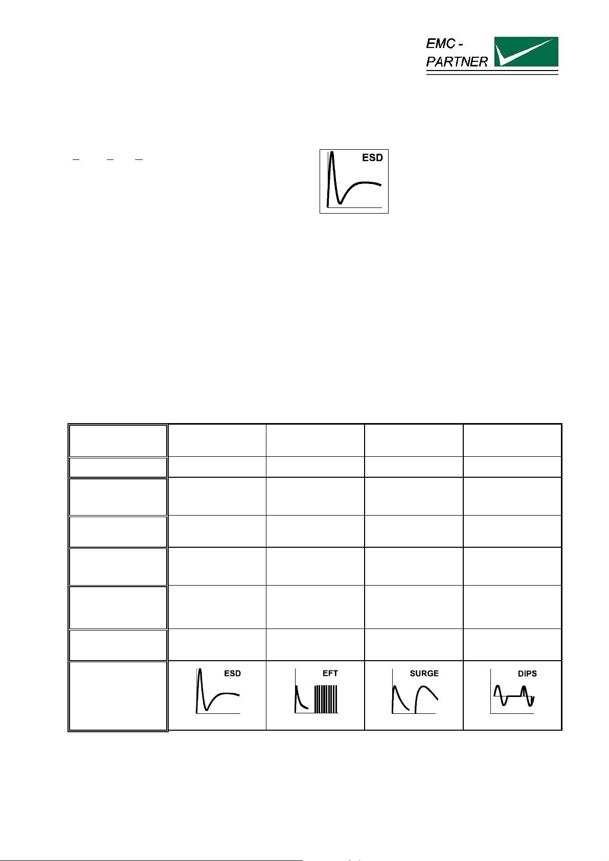
1.1.2 How ESD, EFT, SURGE, DIPS differ
Characteristics Static discharges Switched
inductance
Lightning.
switching actions
Mains
Interruptions
Phenomenon "ESD" "EFT Burst" "Surge" "DIPS"
Voltage U
up to 15 kV up to 4 kV up to 4 kV supply source
voltage
Energy at maximum
voltage
approx. 10 mJ 300 mJ 300 J -
Repetition rate
Single event Multiple event 5 kHz
Maximum 6
Impulse / minutes
supply source
frequency
Application to the
different ports
Touchable metallic
part ( enclosure
ports)
AC/DC ports, Signal
and data lines
AC/DC ports, Signal
and data lines
AC/DC ports
upper limit
frequency
approx.. 1 GHz approx. 200 MHz approx. 350 kHz approx. 100 kHz
impulse waveform
IEC 61000-4-2
IEC 61000-4-4
IEC 61000-4-5
IEC 61000-4-11
The overview of „How ESD,EFT, SURGE, DIPS differ“ shows that all four test have to be carried out
because the frequency content and energy of the four transient tests are different.
ESD3000-System
8/66
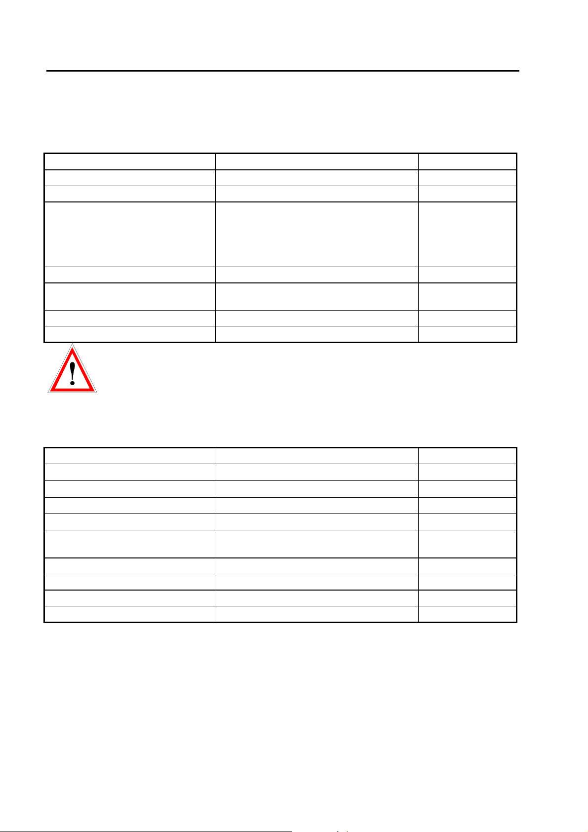
1.2 Technical data of the ESD3000 and DM Discharge Modules
1.2.1 ESD3000 equipment
Supply batteries NIMH standard UM-3/AA size
charging time (empty to full) ca. 5 hours
Polarity positive, negative; alternate
Number of discharges
Detection of the number of
discharges
-preselectable
-count „all“, -count „discharge“. Only the
impulses whereas the voltage of the
discharge capacitor tropes lower then 10%
of the charging voltage are counted.
1 to 29’999
Ramps voltage amplitude changes from shot to shot,
Reporting test sequence with the number of
discharges, voltage amplitude, polarity
Only possible with
control form PC
Discharge modes: see list below
Repetition of the discharges 0.05 up to 30 s or single discharge „Man“
Note: The repetition rates are applicable to IEC 61000-4-2 only. For all other modules or
applications consult the relevant DM (Discharge Modules) or DN (Discharge Network) specific Instruction
sheets.
1.2.2 Discharge Module ESD3000DM1 (IEC 61000-4-2 and EN61000-4-2)
Energy storage capacitance 150 pF ± 10%
Discharge resistance 330 Ω± 10%
Charging resistance 54 MΩ
Holding time (drop to 95%) better than 5 s
Current rise time, 2 Ωload 0,7 to 1 ns
First current amplitude into 2 Ω
„contact discharge“
7,5 to 30 A ± 10%
Current amplitude at 30 ns 4 to 16 A ± 30%
Current amplitude at 60 ns 2 to 8 A ± 30%
Voltage range „air discharge“ 0.2 to 16 kV ± 10%
Voltage range „contact discharge“ 0.2 to 10 kV ± 10%

ESD3000-System
9/66
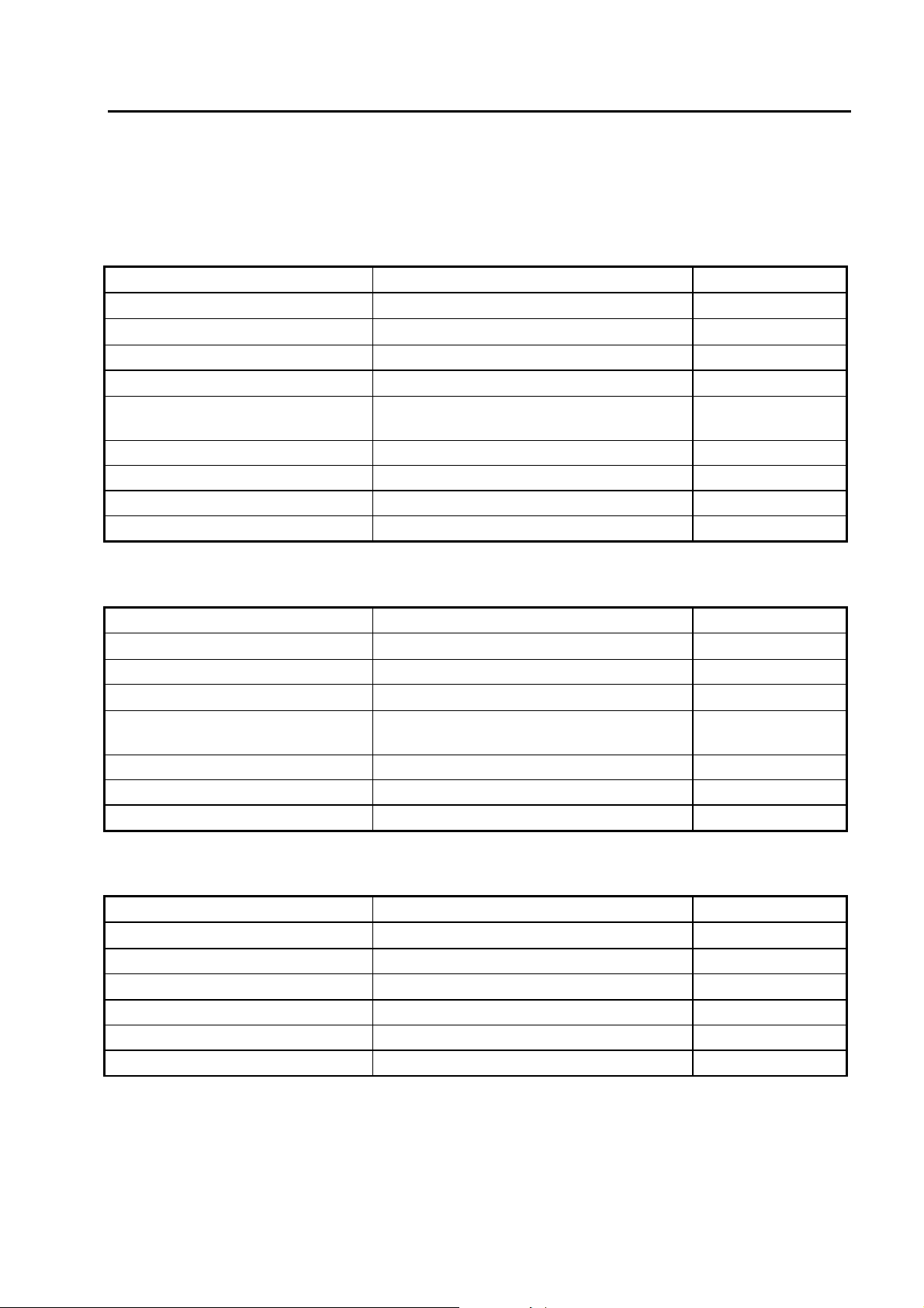
1.2.3 Discharge Module ESD3000DM2 (ISO TR10605 - inside vehicle, module tests)
Energy storage capacitance 330 pF ± 10%
Discharge resistance 2000 Ω± 10%
Holding time (drop to 95%) better than 5 s
Current rise time, 2 Ωload 0,7 to 1 ns
First current amplitude into 2 Ω
„contact discharge“
7,5 to 30 A ± 10%
RC time constant 600 ±130ns
Voltage range „air discharge“ 0.2 to 16 kV ± 10%
Voltage range „contact discharge“ 0.2 to 10 kV ± 10%
1.2.4 Discharge Module ESD3000DM4 (MIL-STD-883E, MIL-STD-464, GR78-CORE)
Energy storage capacitance 100 pF ± 10%
Discharge resistance 1500 Ω± 10%
Holding time (drop to 95%) better than 5 s
Current rise time, 2 Ωload <10 ns at - 4 kV
Peak current 3.33 A at 5 kV
Voltage range „air discharge“ 0.2 to 16 kV ± 10%
Voltage range „contact discharge“ 0.2 to 10 kV ± 10%
1.2.5 Discharge Module ESD3000DM5 (RTCA/DO 160)
Energy storage capacitance 150 pF ± 10%
Discharge resistance 330 Ω± 10%
Holding time (drop to 95%) better than 5 s
Current rise time, 2 Ωload <5 ns at 15 kV
RC time constant 50 ns
Voltage setting accuracy ± 10% for voltages greater than 5 kV and ±
500 V for voltages lower than 5 kV
Voltage range „contact discharge“ 1 to 30 kV ± 10%

ESD3000-System
10/66
1.2.6 Discharge Module ESD3000DM6 (IEC 61340-3-1, JEDEC 22-A114, MIL-STD-750D9)
Energy storage capacitance 100 pF ± 10%
Discharge resistance 1500 Ω± 10%
Discharge mode only contact discharge
Current rise time, 50 Ωload 2 to 10 ns
RC time constant 150 ns
Voltage range 200 V up to 10000 V
Voltage rise time, 500 Ωload 5 to 25 ns
Voltage verification V charging1000V 375 up to 550 V
Voltage range 200 V up to 8000 V
1.2.7 Discharge Module ESD3000DM7 (IEC 61340-3-2, JEDEC 22-A115)
Energy storage capacitance 200 pF ± 10%
Discharge resistance 500 Ω± 10%
Discharge mode only contact discharge
Current waveform, short circuit <1 ΩFirst peak to second peak 67% to 97%
oscillation period 63 ns up to 91 ns
Voltage verification V charging 400V first peak <1.31 A
Voltage verification V charging 400V amplitude at 100 ns 0.29 A -15%
Voltage range 80 V up to 2500 V
1.2.8 Discharge Module ESD3000DM8 (IEC 60571, EN 50155)
Waveform B Risetime 10/90% < 0.05 µs
Half value time 50 % to 50% 0.1 µs ±20%
Voltage amplitude > 8400 V
Series Resistor (Rs) 100Ω±10%
Dimension / Weight l = 120, diameter = 60 mm 0.5 kg
Pulse Repetition Maximum 1 Hz
Required equipment ESD3000 + DM8
Voltage amplitude CD 200V up to 10’000V CD = Contact Discharge
Further Information to additional discharge modules DM or discharge networks DN can be
found in the relevant instruction sheets. or in the ESD3000 brochure.
ESD3000-System
11/66
1.3 Technical data of the ESD3000RM and DN Discharge Networks
For all DN network the ESD3000RM relay module is necessary.
Discharge network ESD3000DN1 (IEC 61000-4-2 and EN61000-4-2)
Energy storage capacitance 150 pF ± 10%
Discharge resistance 330 Ω± 10%
Charging resistance 54 MΩ
Holding time (drop to 95%) better than 5 s
Current rise time, 2 Ωload 0,7 to 1 ns
First current amplitude into 2 Ω
„contact discharge“
7,5 to 30 A ± 10%
Current amplitude at 30 ns 4 to 16 A ± 30%
Current amplitude at 60 ns 2 to 8 A ± 30%
Voltage range „air discharge“ 1 to 30 kV ± 10%
Voltage range „contact discharge“ 1 to 30 kV ± 10%
1.3.1 Discharge Network ESD3000DN2 (ISO TR10605 - inside vehicle, module tests)
Energy storage capacitance 330 pF ± 10%
Discharge resistance 2000 Ω± 10%
Holding time (drop to 95%) better than 5 s
Current rise time, 2 Ωload 0,7 to 1 ns
First current amplitude into 2 Ω
„contact discharge“
7,5 to 30 A ± 10%
RC time constant 600 ±130ns
Voltage range „air discharge“ 1 to 30 kV ± 10%
Voltage range „contact discharge“ 1 to 30 kV ± 10%
1.3.2 Discharge network ESD3000DN3 (ISO TR10605 -outside vehicle, sensitive classification)
Energy storage capacitance 150 pF ± 10%
Discharge resistance 2000 Ω± 10%
Holding time (drop to 95%) better than 5 s
Current rise time, 2 Ωload 5 ns at + 15 kV
RC time constant 300 ±60ns
Voltage range „air discharge“ 1 to 30 kV ± 10%
Voltage range „contact discharge“ 1 to 30 kV ± 10%

ESD3000-System
12/66
1.3.3 Discharge Module ESD3000DN4 (MIL-STD-883E, MIL-STD-464, GR78-CORE)
Technical data
Voltage contact up to 30 kV
Capacitance DN4 500 pF
Serial resistor DN4 5000 Ohm
Weight incl. accessories 0.8 kg
Standard MIL-STD 1512
Standard VG 95378
Usable with testers ESD3000, ESD3000RM32
1.3.4 Discharge Module ESD3000DN5 (MIL-DLT-23659D, STANAG 4239, MIL-STD 331)
Technical data
Voltage contact up to 30 kV
Capacitance 500 pF
Serial resistor 500 Ohm
Weight incl. accessories 0.8 kg
Standard customised
Usable with testers ESD3000, ESD3000RM32
1.3.5 Discharge Module ESD3000DN6 (MIL-DLT-23659D, STANAG 4239, MIL-STD 331)
Technical data
Energy storage capacitance 330 pF ± 10%
Discharge resistance 330 Ω± 10%
Charging resistance 54 MΩ
Holding time (drop to 95%) better than 5 s
Current rise time, 2 Ωload 0,7 to 1 ns
Voltage range „contact discharge“ 1 to 30 kV ± 10%
First current amplitude into 2 Ω„air
discharge“
< 5ns
RC time constant 300 ns ± 60ns
Voltage range „air discharge“ 1 to 30 kV ± 10%
Further Information to additional discharge modules DM or discharge networks DN can be
found in the relevant instruction sheets. or in the ESD3000 brochure.
ESD3000-System
13/66
1.4 Mechanical dimensions
Tester -Type Dimensions [mm] Weight [kg] Versions
width x depth x height
ESD3000 350 x 70 x 200 0.7 19" 4 UH
Discharge Module DM 550 x 600 x 190 0.35 19" 4 UH
The weight slightly differ a little bit from module to module
1.5 Power Consumption
The power supply of the ESD3000 is 42 V d.c.
AD / DC adapter inputs 100 up to 240 V ( 50/60 Hz )
300 mA
± 10 %
Output of AC/DC Adapter 24 V 500 mA

ESD3000-System
14/66
1.6 Accessories, dimensions
1.6.1 Included articles, dimensions
1.6.2 Standard accessories
E-ESD3000-E-Manual.doc 15/66
2 Safety
The ESD3000belongs to Safety class 1
2.1 Safety standard
The ESD3000 fulfils the requirements of the safety standards IEC 61010 for laboratory measurements
equipment „Safety requirements for electrical measuring, control and laboratory equipment“. Based on EN
61010 (IEC61010) the declaration of conformity to low voltage directive (LVD 73/23/EEC O.J.N° L77, 1973-
03-26) is given.
This manual is a integral part of the ESD3000 tester. The instructions
contained in the manual regarding operation and the test set up are to
be strictly observed
2.2 Climatic Conditions
The ESD3000 contains high voltage circuits in integrated form. EMC PARTNER only guarantees a correct
functioning of the tester ESD3000 and the associated accessories, if the ESD3000 is operated in the
climatic condition specified.
Temperature 15 °C to 35 °C Charging voltage up to 25 kV
Relative humidity 10 % to 60 % Charging voltage up to 25 kV
Atmospheric pressure 86 kPa to 106 kPa
(860 to 1060 mbar)
Charging voltage up to 25 kV
Atmospheric condition Voltages > 25 kV
20°C, RH 30%, pressure 101.3 kPa
Contact discharge not influenced by: direct solar radiation, rain or condense water, dust or larger
electro magnetic fields as specified in the EMC compatibility
chapter.
The ESD3000 should be operated in a dry, clean room. If for any reason water condenses in the ESD3000,
then no operation should be started before the tester is dry.
It is strictly forbidden to operate the ESD3000 in rooms with of gas explosion risk.
The high voltage of the ESD3000 generate sparks, which can ignite the gas.
People with heart pacemakers should not be in the vicinity of the test set up during operation.
ESD3000-System
16/66
2.3 Precautionary measure during use
The ESD3000 generates high voltages. The energy content of the 30 kV modules is high
and can be dangerous with improper use. It is wise to observe the following rules
•Never touch the EUT when a test is in operation.
•Touch no connectors of connection cable or tips when a EMC test is in operation.
•The high voltage of the ESD3000 and the power on the EUT must turned off before a manipulation on
the EUT is carried out.
•For all tests the 2 m ground cable must be connected to ground.
2.4 Electromagnetic Compatibility
The outputs of the ESD3000 and the discharge to the EUT will emit disturbances.
Please consider the national emission rules.
The Test System ESD3000 should not be operated near sensitive measuring and
control systems.
The ESD3000 fulfils the following immunity requirements
•Electrostatic discharge Level 4 (8 kV) (IEC 61000-4-2)
2.5 The manual is an integral part of the equipment. Refer to the manual.
This manual is an integral part of the ESD3000. The safety rules and precautions in the manual must
be observed. EMC PARTNER and their representatives are not responsible for damage to persons
and equipment by not observance the safety rules and precautions in the manual.
2.6 No operation of ESD3000 without ground wire
The ESD3000 must be operated with a ground wire attached to the battery case

E-ESD3000-E-Manual.doc 17/66
3 Mechanical structure
3.1 General
The battery operated ESD3000 is ideal for running tests in development/test laboratory environments and
for outdoor service on larger systems.
3.2 Overview on ESD3000 system
3.2.1 ESD3000 Contact Discharge (CD) up to max. 10kV with Discharge Module (DM )
3.2.2 ESD3000 Contact Discharge (CD) up to max. 30kV with (RM and (DM )
ESD3000 Contact Discharge (CD) up to 30 kV) with Relay Module (RM), Discharge Network (DN)
ESD3000
Batteries
standard
VM size 3
Discharge Module (DM)
Sharp Tip for
contact discharge (CD)
Rounded Tip for
air discharge (AD)
30 mm Tip Electrode for
(AD) V > 16 kV
ESD3000
Batteries
standard
VM size 3
Sharp Tip for
contact discharge (CD)
Rounded Tip for
air discharge (AD)
30 mm Tip Electrode for
(AD) V > 16 kV
Discharge
Network (DN)
Relay Module
(RM)

ESD3000-System
18/66
The ESD test System consist of ESD3000, the discharge modules (DM) or relay module and networks.
The batteries, the charger and control are part of ESD3000. The discharge modules or networks includes
the high voltage generation and the wave-shaping network.
ESD3000 with one discharge module Discharge Module
The screw on the bottom side of the ESD3000 must be unscrewed, before the DM can be pull out and
changed with an other one. The modules can be inserted only in one position.
3.2.3 Avoiding Mechanical Damage to Discharge Modules
ESD3000 discharge modules contain components sensitive to mechanical shock. When modules suffer
mechanical shock they can be damaged beyond repair.
When ESD3000 modules are not in use, place them in the transport case. Do not
allow them to roll around on the test bench or fall onto the floor.
Positioning part of the
discharge modules

E-ESD3000-E-Manual.doc 19/66
4 Control Panel
4.1 Front panel of the ESD3000
The operator should study the manual in detail. Only instructed personal is allowed to operate the ESD3000.
The most important elements of the front panel are:
1. Display
2. Voltage up or menu command line up
3. Voltage down or menu command line down
4. Run button: With the „Run“ button, a test can be started or interrupted. With the run button the unit is
turned „ON“
5. Enter
6. Selection of the programmed test levels. The programmed test levels changes with discharge module
interchange
7. Polarity selection
8. Screw for looking the discharge modules. The same screw can be used for fix the ESD3000 on a
tripod stand.
9. Trigger button: When manual trigger is programmed and the tester is ready for manual trigger, this will
be signalled by the LED. As soon as the signal occurs the pulse can be released.
2
9
8
7
6
5
4
1
3
ESD3000-System
20/66
4.2 Interchange of discharge modules
Loose the screw 8 and pull the discharge module out.
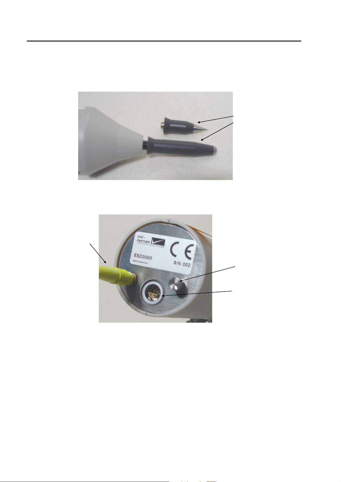
4.3 Interchange of the finger and tips
Pull out the finger and
insert the tip
CD = sharp tip
AD = finger electrode
4.4 Inputs and Outputs
The control of the ESD3000 is carried out by a microprocessor. The microprocessor controls the EMC tests,
stores the inputs of the numeric input terminal, updates the display, checks whether the inputs of the
operators are allowed values or not. The operator communicates with the ESD3000 via the input terminal
and the display.
This plate is reserved for the CE mark. The CE -mark is needed for the free movement of the goods into
and within European community.
Via this interface port, the ESD3000 can be also controlled by an external PC. To configure the interface,
see Chapter 13 „Remote Control“.
Ground connection 2 m
Screw holding the
battery module
Input for charging the
batteries, and RS232
input for remote control
Table of contents
Other EMC-PARTNER Test Equipment manuals


Popular Test Equipment manuals by other brands

Bosch
Bosch DAS 3000 S20 Original instructions

Batterytester
Batterytester AT00001 Quick manual

Kurth Electronic
Kurth Electronic xDSL MultiTest KE3700 Short Operating Manual

MULTI MEASURING INSTRUMENTS
MULTI MEASURING INSTRUMENTS 104 instruction manual

MITECH
MITECH MH600 user manual

Aeroflex
Aeroflex IFR 4000 Calibration


