manuals.online logo
Brands
  1. Home
  2. •
  3. Brands
  4. •
  5. Fluke
  6. •
  7. Test Equipment
  8. •
  9. Fluke 810 User manual

Fluke 810 User manual

How to Answer the Setup Questions
for a Vibration Test with the
Fluke 810 Vibration Tester
The Fluke 810 Vibration Tester can accurately diagnose a
wide range of machine conditions, but to do so it must have
a complete and accurate description of the components being
tested and how they are configured.
To gather the required information quickly and conveniently, the
Tester asks a series of questions about the following when you
set up a new test:
•The motor that drives the system
•The couplings and transmission
•The driven component
As you answer these questions, the Fluke 810 Vibration Tester
displays an image of the system that you have described so you
can be sure that it has an accurate representation.
Motor
Coupling
Blower
Motor
Coupling
Blower
Entering Motor Information
Entering an accurate
running speed (RPM)
is critical to receiving
a proper diagnosis.
The Fluke 810 Vibration Tester
uses the running speed that
you enter to analyze vibration
information and to give you an
accurate diagnosis. Entering
an incorrect running speed
significantly reduces the
accuracy of the tester. Use
the keypad of the Fluke 810
Vibration Tester to enter the
running speed. (Figure 1)
Getting the speed information for constant-speed motors
You can get the speed of a constant-speed motor from the motor nameplate or
the motor manual. You can also measure RPM with tachometer supplied with
the Fluke 810.
Getting the speed information for variable-speed motors
You can get the speed of a variable-speed motor from:
•The tachometer supplied with the Fluke 810 Vibration Tester
•A separate strobe or contact tachometer
•The information listed on the variable frequency drive
To get consistent diagnoses on motors controlled by variable speed drives
(VFDs), it may be necessary to reduce or increase the load on the motor to get
the motor speed to match the speed at which previous measurements were
made. If you can manually adjust the VFD, set the VFD to its maximum output
speed (50Hz or 60Hz).
To calculate motor speed from the VFD output setting, use the following formula:
VFD output frequency / motor nameplate frequency
×motor nameplate speed = motor speed
For example, if the motor nameplate tells you that that motor speed at 60 Hz is
1,775 RPM and you set the VFD to 60 Hz, the motor runs at its nameplate speed:
60 Hz / 60 Hz ×1,775 RPM = 1,775 RPM
If you reduce the VFD to half the previous output frequency, the motor runs
half as fast:
30 Hz / 60 Hz ×1,775 RPM = 887 RPM
Figure 1
Vibration Tester
810
Using the Machine Setup Wizard
When you set up a machine for measurement and diagnosis using the
Machine Setup Wizard, answer each question carefully and correctly, based
on your knowledge of the machine to be tested. If you are unsure about
how to interpret the questions asked by the Machine Setup Wizard, refer to
the Fluke 810 Users’ Manual or this guide.
•Use the Dial on the Fluke 810 to highlight your choice. (Figure 2)
•Use the softkeys to select the component, and then press Enter (Figure 3)
Figure 2
Figure 3
Softkeys
7. Motor detached from drive train?
Answer NO unless:
a. The driven component is physi-
cally disconnected from the motor
- or -
b. You want to test only the motor and
not any attached components. (If a
or b is true, answerYES).
Detached Motor
8. Motor Close Coupled?
Answer NO unless:
a. The motor shaft is driving the
driven component directly
- and -
b. The only bearings are on the motor
shaft (for example, when the motor
is bolted directly to a fan, a pump,
or a compressor)
Then, answer YES.
Motor Close Coupled
Also called “direct mount” or
“direct drive,” a motor is “
close-coupled” if:
•There are no bearings on
the driven unit.
•There is only one shaft
running at one speed
9. Coupling between motor and next
component?
Flexible Coupling
If there is flexible
material between the
flanges of the coupling,
answer YES.
Rigid Coupling
Otherwise, if the
coupling is rigid and
the flanges are bolted
together with no
flexible material, or no
coupling, answer NO.
Next component: Press Enter on the
center of the Dial, rotate the Dial, and
select the driven unit.
If the driven unit is a gearbox,
go to step 11. Otherwise,
go to step 12.
Flexible or Rigid Coupling
Regardless of coupling type:
•There are bearings on
both the motor and the
driven shafts
•There are two shafts, both
running at the same speed
Flexible Coupling
Rigid Coupling
If in doubt, select
Flexible Coupling.
Measurement locations
Motor
Flexible coupling
Shaft
Gearbox
Fan
Belt drive Bearing
Create A New Machine Setup Answers And Diagrams
1. Push New Machine on the startup
screen. Or push SETUP.
Use the Dial to select and enter
characters.
2. Enter a machine name:
Enter a descriptive name for the ma-
chine, for example, B5 Supply Fan 3.
A maximum of 15 characters is
allowed.
Machine Setup Questions
1. Select motor type: AC DC
2. AC motor with VFD: Yes No
Select a variable frequency drive
(“Yes”) or a constant speed motor
(“No”).
3. Enter speed in RPM:
Enter the speed from the motor’s
nameplate or the tachometer.
4. Enter nominal hp (kw):
Enter the horsepower or kilowatts
listed on the motor’s nameplate.
Press Next Page.
5. Motor mounted: Horiz/Vert
Specify whether the motor shaft is
horizontal or vertical.
6. Motor bearing type: Roller/Journal
Choose roller or journal bearings.
Roller or Journal Bearings
Roller Bearing
Roller bearings
support a load
with round
rolling elements
Journal Bearing
Journal bearings
support a load
without round
rolling elements
If in doubt,
select Roller Bearings.
Flexible coupling bearing
Journal bearing
Cylindrical roller bearing
Rigid coupling bearing
Flexible coupling bearing
Journal bearing
Cylindrical roller bearing
Rigid coupling bearing
Setup Questions and Results
Answering the Setup Questions
Use the Fluke 810 User’s Manual and this guide to help answer the setup questions
required for each test.
Symbols used in this guide
10.
Coupling between motor and next
component? Answer “No.”
Next component: Belt Drive
Press Enter on the center of the Dial,
rotate the Dial, then select Belt Drive.
Input shaft speed:
Enter the motor shaft speed.
Output shaft speed:
Enter the driven unit shaft speed.
Rotation speed (optional):
Use a strobe or contact tachometer to
measure the speed of the belt.
Next component: Press Enter on
the center of the Dial, rotate the Dial,
then select driven unit.
If the next component is Gearbox,
skip to #13.
Belt driven machine
•Bearings on motor and
driven shafts
•Two shafts with
different speeds
11.
After completing the steps in #9:
Next component: Gearbox
Press Enter on the center of the Dial,
rotate the Dial, then select Gearbox.
Gearbox bearing type: Roller/
Journal
Select roller or journal bearings.
Number of speed changes: 1/2 /3
Scroll and select the number of
changes.
What is known: Shaft speeds/
Gear ratios/Gear Teeth Count
Make selection and enter either shaft
speeds, gear ratio, or gear teeth count.
Flexible coupling between gearbox
and next component? Yes/No
Select whether there is or isn’t a
coupling between the gearbox and
the coupling.
Next component that gearbox is
attached to:
Press Enter on the center of the Dial,
rotate the Dial, then select the
driven unit.
If the next component is a belt
drive, skip to #14.
Gear driven machine
•Bearings on motor, gearbox
and driven shafts
•Motor shaft, gear shafts,
driven shaft – different
speeds
If in doubt, use input and
output shaft speeds to
calculate ratio.
Always use number one in
ratio – 4.25:1 (reducer) or
1:4.25 (increaser).
12.
After completing the steps in #9:
Next component:
Press Enter on the center of the Dial,
rotate the Dial, then select Driven
unit - Pump, Fan, Compressor,
Blower, or Spindle.
Driven component (Fan) bearing
type: Roller / Journal
Select roller or journal bearings.
Driven Unit (Fan) is supported by:
Two Bearings/Overhung
“Two bearings” means the fan is sup-
ported on both sides (see diagram)
“Overhung” the fan is mounted at the
end of the shaft unsupported on one
side.
No. of fan blades [optional]:
If you are certain you know the num-
ber of blades, enter the number.
If not, leave blank.
When you are done, select Next
Page, and then select Done.
Supported or Overhung
Component
If in doubt, select spindle
for all driven units that
are not a pump, fan,
compressor, or blower.
Blower refers to a driven
with multi-stage centrifugal
wheels or lobes, not a fan
with blades (should be
setup as a fan).
Screw compressors –
select roller bearings even
if you have journals.
13.
After completing the steps in #10:
Next component: Gearbox
Press Enter on the center of the Dial,
rotate the Dial, then select Gearbox.
Then follow steps in #11 for Gearbox.
Belt and Gearbox driven
machines
14.
After completing the steps in #11:
Next component: Belt drive
Press Enter on the center of the Dial,
rotate the Dial, then select Belt drive.
Then follow steps in #10 for Belt
drive.
©2013 Fluke Corporation.
Specifications subject to change without notice.
Printed in U.S.A. 6/2013 4161309B_EN
Modification of this document is not
permitted without written permission from
Fluke Corporation.
Fluke. The Most Trusted Tools
in the World.
Supported Fan
Overhung Fan
Other manuals for 810

3

Other Fluke Test Equipment manuals

Fluke 80PK-27 User manual

Fluke

Fluke 80PK-27 User manual

Fluke NFK-LAUNCH Series User manual

Fluke

Fluke NFK-LAUNCH Series User manual

Fluke 714B User manual

Fluke

Fluke 714B User manual

Fluke AIRCHECK Instruction manual

Fluke

Fluke AIRCHECK Instruction manual

Fluke PRV240FS User manual

Fluke

Fluke PRV240FS User manual

Fluke TS 1200 User manual

Fluke

Fluke TS 1200 User manual

Fluke IT100 IntelliTone Toner User manual

Fluke

Fluke IT100 IntelliTone Toner User manual

Fluke 80T-150U User manual

Fluke

Fluke 80T-150U User manual

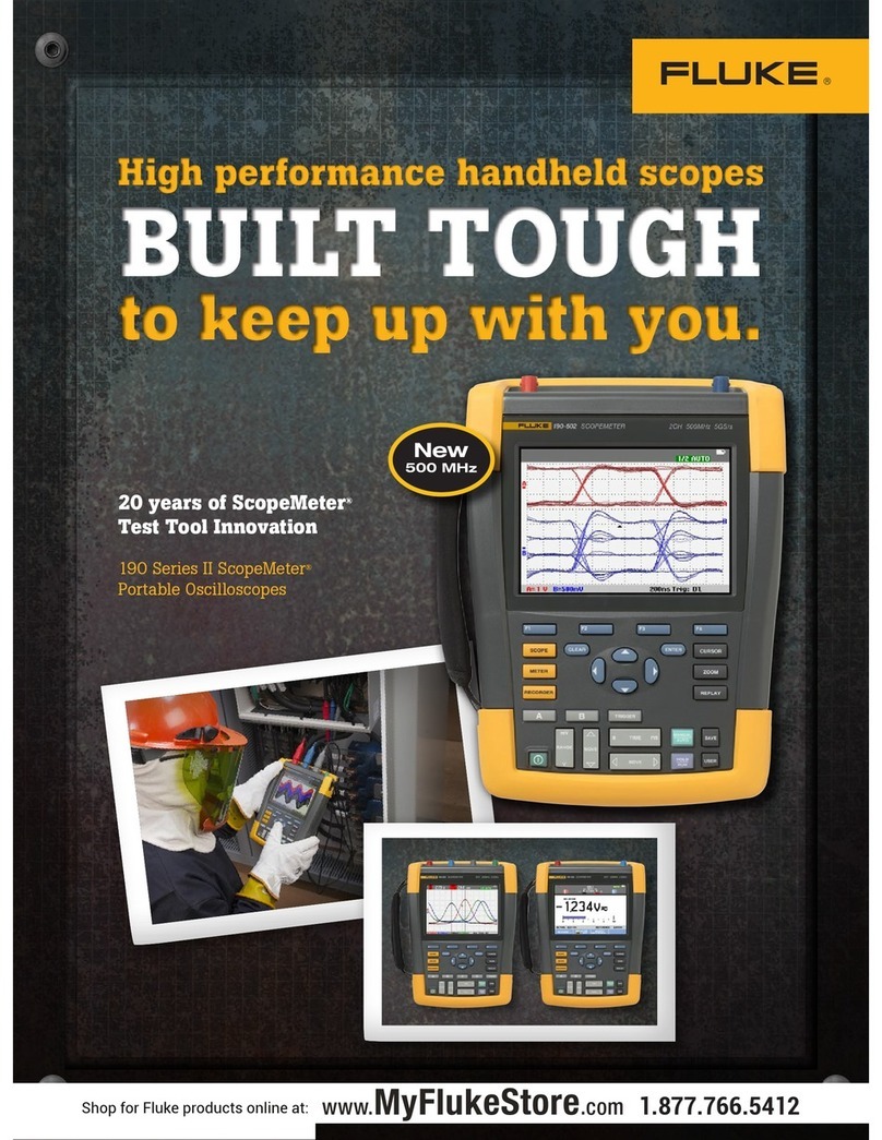
Fluke ScopeMeter 190-502 User manual

Fluke

Fluke ScopeMeter 190-502 User manual

Fluke 1535 User manual

Fluke

Fluke 1535 User manual

Fluke T5-600 Operating and installation instructions

Fluke

Fluke T5-600 Operating and installation instructions

Fluke 1746 Use and care manual

Fluke

Fluke 1746 Use and care manual

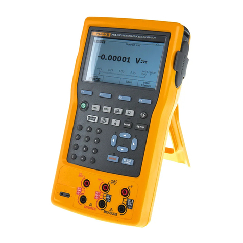
Fluke 753 User manual

Fluke

Fluke 753 User manual

Fluke TS22 User manual

Fluke

Fluke TS22 User manual

Fluke 714C User manual

Fluke

Fluke 714C User manual

Fluke 9009 User manual

Fluke

Fluke 9009 User manual

Fluke 715 User manual

Fluke

Fluke 715 User manual

Fluke TS 42DLX User manual

Fluke

Fluke TS 42DLX User manual

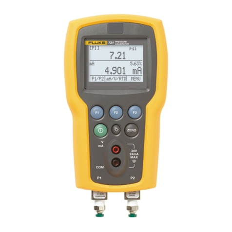
Fluke 721 User manual

Fluke

Fluke 721 User manual

Fluke OF-500 OptiFiber User manual

Fluke

Fluke OF-500 OptiFiber User manual

Fluke FTK100 User manual

Fluke

Fluke FTK100 User manual

Fluke 190 Series II User manual

Fluke

Fluke 190 Series II User manual

Fluke 154 User manual

Fluke

Fluke 154 User manual

Fluke 753 User manual

Fluke

Fluke 753 User manual

Popular Test Equipment manuals by other brands

digi-tech QM-7300 user manual

digi-tech

digi-tech QM-7300 user manual

M-TI 1510A Software Operation manual

M-TI

M-TI 1510A Software Operation manual

X-Vision XTM020 instruction manual

X-Vision

X-Vision XTM020 instruction manual

Show Tec RT-200 manual

Show Tec

Show Tec RT-200 manual

Fineart FINE 2970W/1080C manual

Fineart

Fineart FINE 2970W/1080C manual

Pite 3830 user manual

Pite

Pite 3830 user manual

TankRadar REX RTG 3900 Commissioning manual

TankRadar REX

TankRadar REX RTG 3900 Commissioning manual

HP 8921A Programmer's guide

HP

HP 8921A Programmer's guide

Tektronix TBS1000C Series Technical reference

Tektronix

Tektronix TBS1000C Series Technical reference

SEW 6210 IN Operation manual

SEW

SEW 6210 IN Operation manual

eXact Pool EZ quick start guide

eXact

eXact Pool EZ quick start guide

Major tech MT474 instruction manual

Major tech

Major tech MT474 instruction manual

SIGLENT SDS2000X Series user manual

SIGLENT

SIGLENT SDS2000X Series user manual

Telwin DT400 instruction manual

Telwin

Telwin DT400 instruction manual

Owon PDS8102T user manual

Owon

Owon PDS8102T user manual

Mark-10 TT05 Series user guide

Mark-10

Mark-10 TT05 Series user guide

TESTING 1.0366 operating manual

TESTING

TESTING 1.0366 operating manual

Megger DET2/2 user guide

Megger

Megger DET2/2 user guide

manuals.online logo
manuals.online logoBrands
  • About & Mission
  • Contact us
  • Privacy Policy
  • Terms and Conditions

Copyright 2025 Manuals.Online. All Rights Reserved.