CIRCUIT DESIGN WA-TBT-03S User manual

OG_WA-TB-03S_v10e 1 Circuit Design, Inc
OPERATION GUIDE
OPERATION GUIDE
Test board for WA-TX-03S, WA-RX-03S
WA-TBT-03S and WA-TBR-03S
Operation guide
Version 1.0 (May 2017)
CIRCUIT DESIGN, INC.,
7557-1 Hotaka, Azumino-city
Nagano 399-8303 JAPAN
Tel: + +81-(0)263-82-1024
Fax: + +81-(0)263-82-1016
http://www.cdt21.com

OG_WA-TB-03S_v10e 2 Circuit Design, Inc
OPERATION GUIDE
OPERATION GUIDE
CONTENTS
GENERAL DESCRIPTION AND FEATURES....................................2
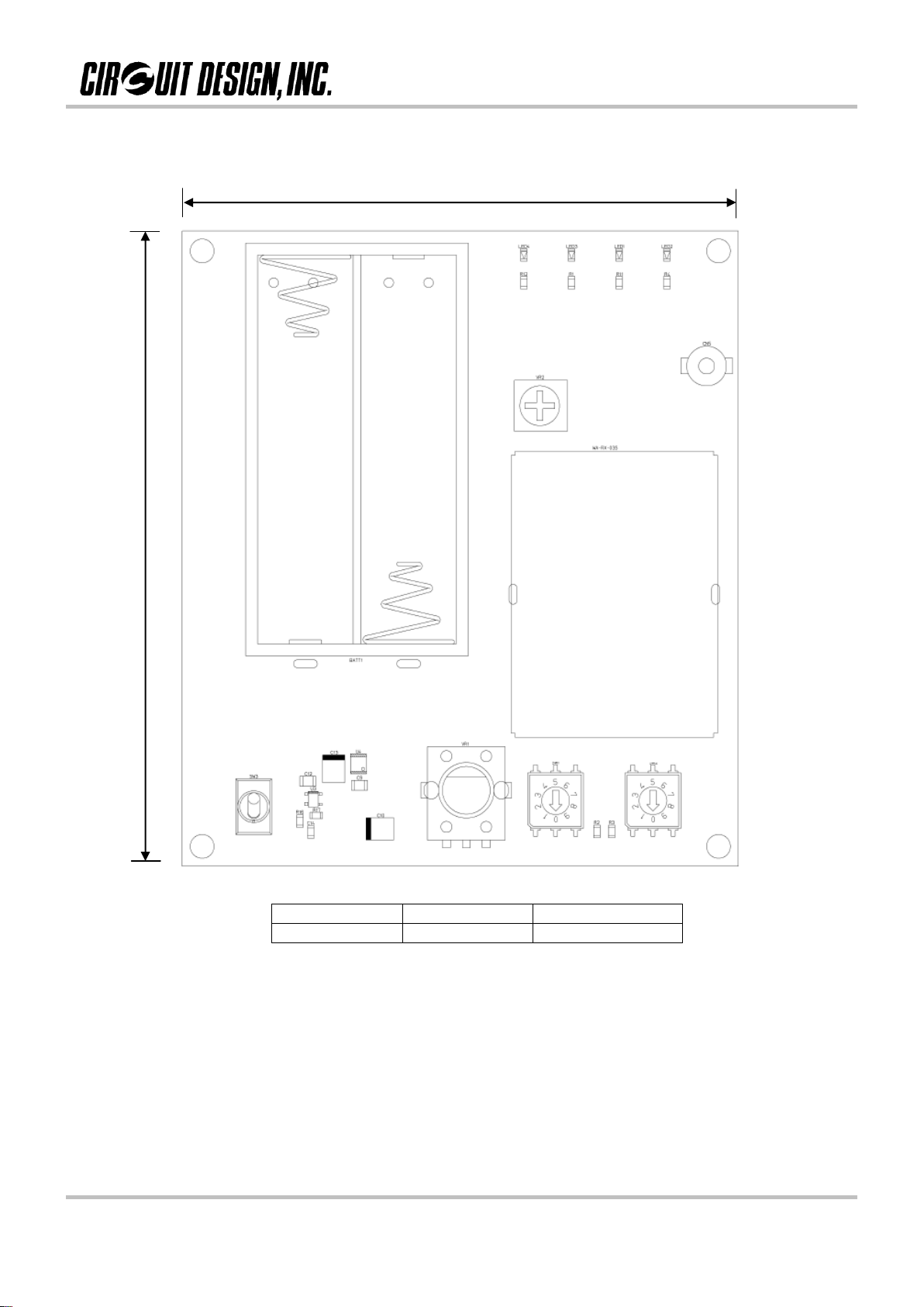
TEST BOARD LAYOUT ....................................................................3
POWER SUPPLY......................................................………………...4
FREQUENCY SELECTION......................................................……..4
OTHER SETTINGS.................................................................……...5
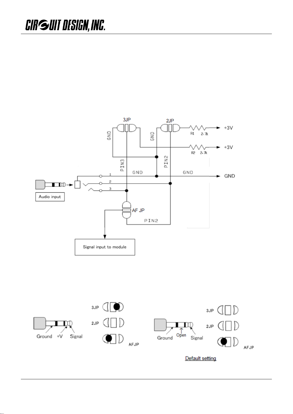
CONNECTING THE MIC...................................................................6
CAUTION NOTICE…...…………………………………………………..7
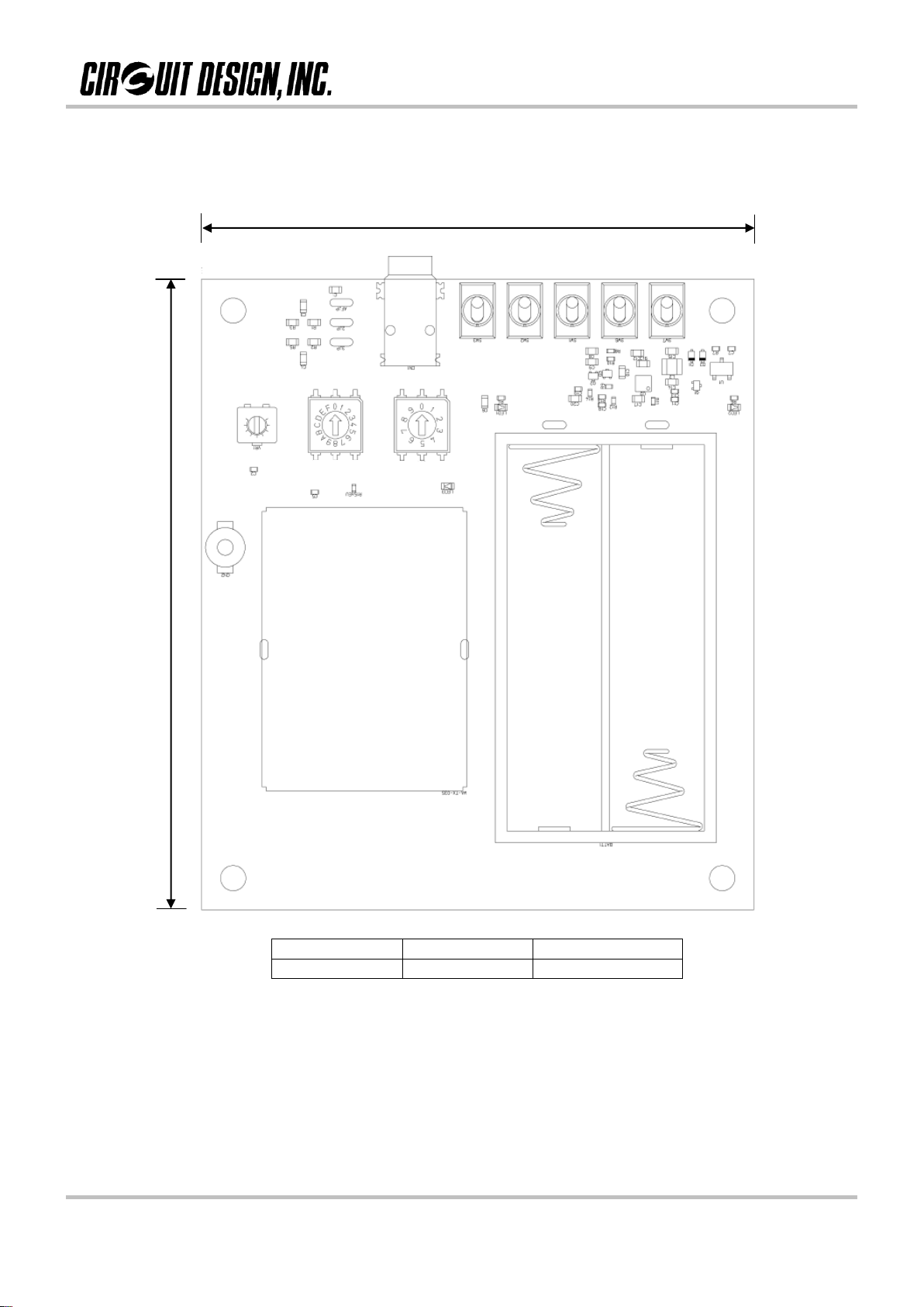
DIMENSIONS……………………………………………………………..8
CIRCUIT DIAGRAM……………………………………………………...10
CAUTIONS & WARNINGS……………………………………………….12
REVISION HISTORY ........................................................................13
GENERAL DESCRIPTION & FEATURES
General description
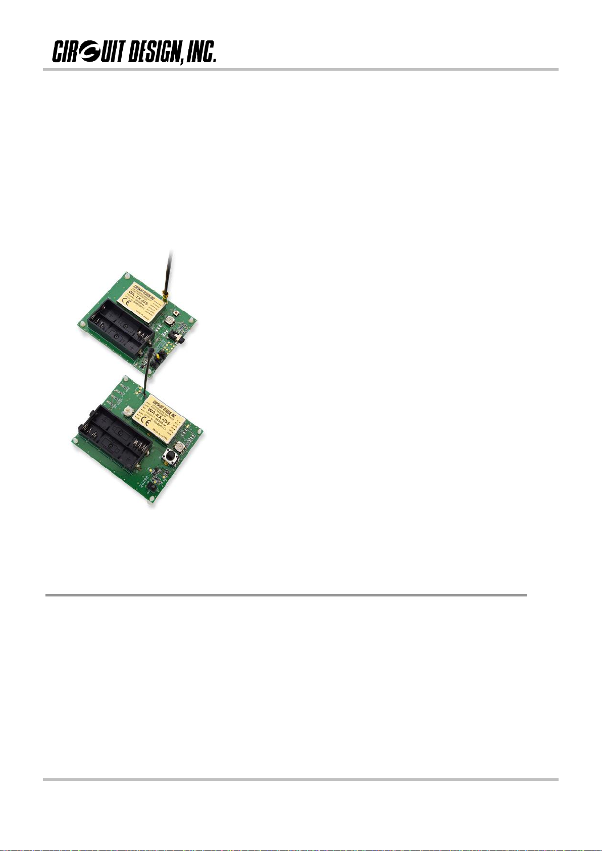
This test board is developed to allow you to evaluate the performance of WA-TX-03-R and
WA-RX-03-R or WA-TX-03S and WA-RX-03S without any additional components.
The board consists of a DC/DC converter, LEDs, a battery case and a module.
WA-TBT-03S and WA-TBR-03S do not include modules WA-TX-03-R and WA-RX-03-R or
WA-TX-03S and WA-RX-03S. Please make sure to order them if needed.
Features
Mounted battery holder
Rotary switch for frequency selection
Audio input level adjust (TX)
Volume control (RX)
Microphone/audio input (3.5mm socket)
Audio / headphone output (3.5mm socket)
Audio cut off
RF Power selection (WA-TX-03S only)
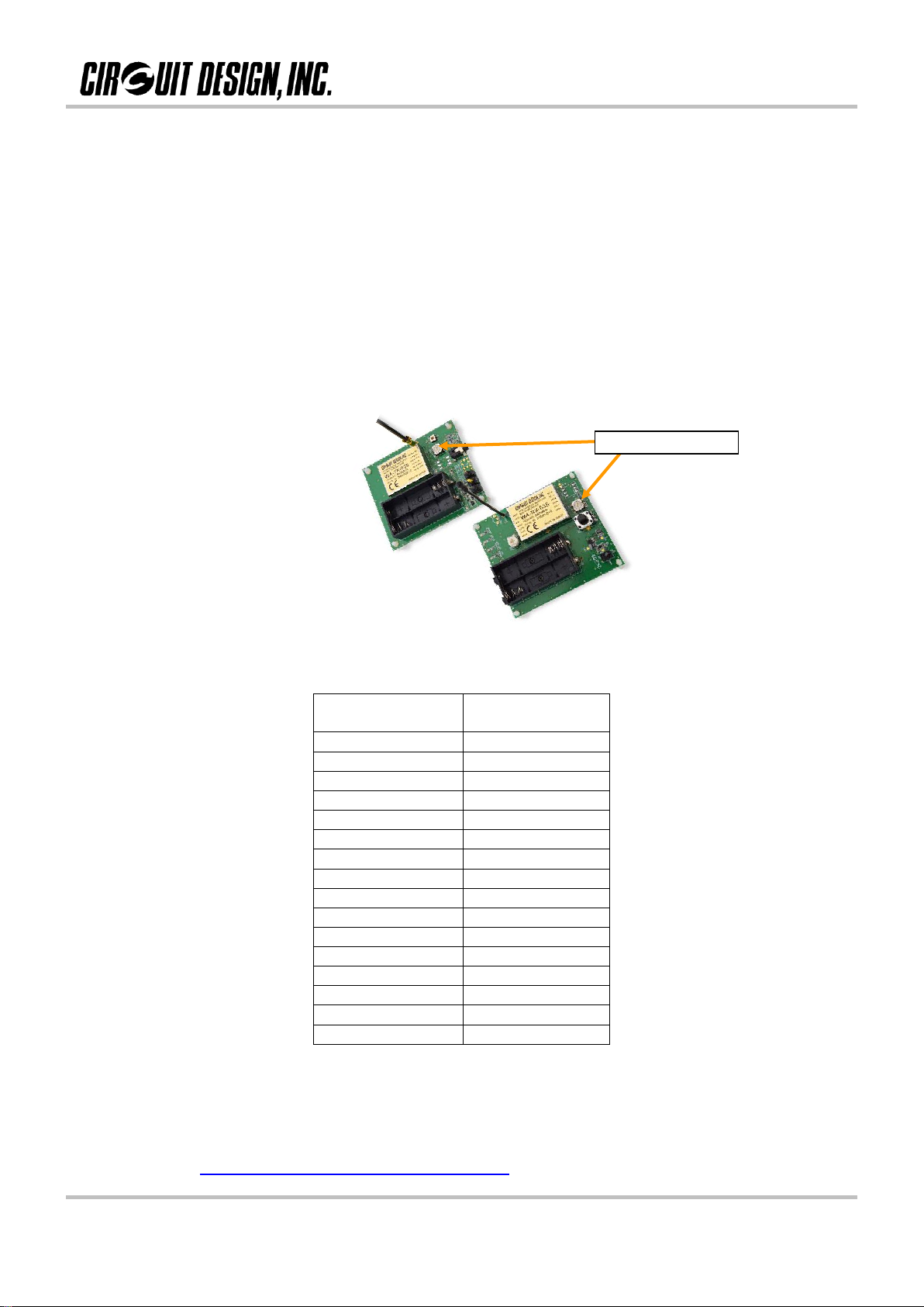
Standby switch (Yellow)

OG_WA-TB-03S_v10e 3 Circuit Design, Inc
OPERATION GUIDE
OPERATION GUIDE
TEST BOARD LAYOUT
WA-TBT-03S
WA-TBR-03S
Batteries: 2 xAAA, 1.5 V

OG_WA-TB-03S_v10e 4 Circuit Design, Inc
OPERATION GUIDE
OPERATION GUIDE
POWER SUPPLY
WA-TBT-03S, 2 xAAA size, 1.5v
WA-TBR-03S, 2 xAAA size, 1.5v
FREQUENCY SELECTION
Select the frequency channel by using the rotary switches. Ensure they are the same on both the
WA-TBT-03S and WA-TBR-03S boards.
Channel
(Rotary switch)
Frequency (MHz)
0
Not available
1
863.125
2
863.250
3
863.375
4
863.500
5
863.625
6
863.750
7
863.875
8
864.000
9
864.125
A
864.250
B
864.375
C
864.500
D
864.625
E
864.750
F
864.875
Attention:
If there are more than 2 transmitters and 2 receivers operating in the same area, one must be
careful of third-order intermodulation interference. To avoid this, it is recommended to plan your
channel usage by using our calculation tool.
Details of the calculation tool and explanation of third-order intermodulation interference can be
found at: http://www.cdt21.com/resources/siryo6.asp
Channel select

OG_WA-TB-03S_v10e 5 Circuit Design, Inc
OPERATION GUIDE
OPERATION GUIDE
OTHER SETTINGS
Standby Switch (STB / yellow)
Standby disables RF emission and puts
the module into standby.
TX: Module does not go into standby
during power shut off.
AUTO: During power OFF, the module
enters standby initially allowing a more
controlled power down cycle. This avoids
audio spikes heard at the receiver.
CENTER POS.: No function
RF power select (EUP)
Select RF power level.
H –High (10 mW)
L –Low (5 mW)
WA-TX-03S only.
The switch has no effect when using WA-TX-03-R
Mute level adjustment
This is the received RF
signal level threshold control.
If the RF falls below this
level, the audio output is
muted. The “AF ON” LED will
go out when the audio is
muted.
Rotate to adjust
audio output
volume.
Ch. not
available LED
Power switch
“AF ON” LED

OG_WA-TB-03S_v10e 6 Circuit Design, Inc
OPERATION GUIDE
OPERATION GUIDE
CONNECTING THE MIC
You may use a 2 or 3-line condenser microphone or dynamic microphone. You must use 3.5mm
mono plug only.
A condenser microphone requires a power supply (phantom supply) to drive it. The WA-TBT-03S
board is able to supply this phantom power via the connector.
There are various microphone types available on the market, so please consult the microphone
datasheets and if necessary add solder to the three jumper locations as shown below. These
jumpers are labeled on the WA-TBT-03S board as 3JP, 2JP and AF JP.
Two / Three wire condenser microphone Dynamic microphone or audio signal
Apply solder to 3JP and AF JP Apply solder to AF JP as shown below

OG_WA-TB-03S_v10e 7 Circuit Design, Inc
OPERATION GUIDE
OPERATION GUIDE
Caution notice
Adjacent channel interference
In some cases, audio maybe heard on the channels immediately either side of the used channel. This is due
to a strong level of RF being received and spilling onto the adjacent channel.

OG_WA-TB-03S_v10e 8 Circuit Design, Inc
OPERATION GUIDE
OPERATION GUIDE
DIMENSIONS
WA-TBT-03S
863 MHz
EU
SW5 only
808 MHz
JP
SW5 & SW4
80
70
SW5
SW4

OG_WA-TB-03S_v10e 9 Circuit Design, Inc
OPERATION GUIDE
OPERATION GUIDE
WA-TBR-03S
863 MHz
EU
SW1 only
808 MHz
JP
SW1 & SW2
70
80
SW1
SW2

OG_WA-TB-03S_v10e 10 Circuit Design, Inc
OPERATION GUIDE
WA-TBT-03S

OG_WA-TB-03S_v10e 11 Circuit Design, Inc
OPERATION GUIDE
WA-TBR-03S

OG_WA-TB-03S_v10e 12 Circuit Design, Inc
OPERATION GUIDE
OPERATION GUIDE
Cautions
As the product communicates using electronic radio waves, there are cases where transmission will be
temporarily cut off due to the surrounding environment and method of usage. The manufacturer is exempt from
all responsibility relating to resulting harm to personnel or equipment and other secondary damage.
Do not use the equipment within the vicinity of devices that may malfunction as a result of electronic radio waves
from the product.
The manufacturer is exempt from all responsibility relating to secondary damage resulting from the operation,
performance and reliability of equipment connected to the product.
Communication performance will be affected by the surrounding environment, so communication tests should be
carried out before actual use.
Ensure that the power supply for the product is within the specified rating. Short circuits and reverse connections
may result in overheating and damage and must be avoided at all costs.
Ensure that the power supply has been switched off before attempting any wiring work.
The case is connected to the GND terminal of the internal circuit, so do not make contact between the '+' side of
the power supply terminal and the case.
When batteries are used as the power source, avoid short circuits, recharging, dismantling, and pressure.
Failure to observe this caution may result in the outbreak of fire, overheating and damage to the equipment.
Remove the batteries when the equipment is not to be used for a long period of time. Failure to observe this
caution may result in battery leaks and damage to the equipment.
Do not use this product in vehicles with the windows closed, in locations where it is subject to direct sunlight, or
in locations with extremely high humidity.
The product is neither waterproof nor splash proof. Ensure that it is not splashed with soot or water. Do not use
the equipment if water or other foreign matter has entered the case.
Do not drop the product or otherwise subject it to strong shocks.
Do not subject the equipment to condensation (including moving it from cold locations to locations with a
significant increase in temperature.)
Do not use the equipment in locations where it is likely to be affected by acid, alkalis, organic agents or corrosive
gas.
The GND for the product will also affect communication performance. If possible, ensure that the case GND and
the circuit GND are connected to a large GND pattern.
Warnings
Do not take apart or modify the equipment.
Do not remove the product label (the label attached to the upper surface of the product.) Using a product from
which the label has been removed is prohibited.
Circuit Design, Inc. All right reserved
No part of this document may be copied or distributed in part or in whole without the prior written
consent of Circuit Design, Inc.
Customers are advised to consult with Circuit Design sales representatives before ordering.
Circuit Design, Inc. believes the furnished information is accurate and reliable. However, Circuit Design,
Inc. reserves the right to make changes to this product without notice.

OG_WA-TB-03S_v10e 13 Circuit Design, Inc
OPERATION GUIDE
OPERATION GUIDE
REVISION HISTORY
Version
Date
Description
Remark
1.0
May 2017
The first issue
This manual suits for next models
1
Table of contents
Other CIRCUIT DESIGN Test Equipment manuals