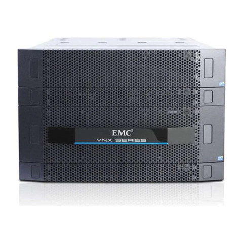
EMC CLARiiON CX3-40c User manual

EMC® CLARiiON® CX3-40c
Setup Guide
P/N 300-003-745
REV. A02

Notice
Copyright © 2006-2007 EMC Corporation. All rights reserved.
Published July, 2007
EMC believes the information in this publication is accurate as of its publication date. However, the information is
subject to change without notice.
THE INFORMATION IN THIS PUBLICATION IS PROVIDED “AS IS.” EMC CORPORATION MAKES NO
REPRESENTATIONS OR WARRANTIES OF ANY KIND WITH RESPECT TO THE INFORMATION IN THIS
PUBLICATION, AND SPECIFICALLY DISCLAIMS IMPLIED WARRANTIES OF MERCHANTABILITY OR
FITNESS FOR A PARTICULAR PURPOSE.
Use, copying, and distribution of any EMC software described in this publication require an applicable software
license.
For the most up-to-date listing of EMC product names, see EMC Corporation Trademarks on EMC.com.
All other trademarks used herein are the property of their respective owners.

1
Overview
Some functions described in this document may not be supported by all revisions of the
software or hardware currently in use. For the most up-to-date information on product
features, refer to your product release notes.
A basic CLARiiON® CX3-40c storage system contains the following:
•A storage processor enclosure (SPE3) with two storage processors (SPs) and
redundant power/cooling. Each SP includes both Internet SCSI (iSCSI) and Fibre
Channel host data ports.
•At least one disk-array enclosure (DAE3P) with a minimum of five Fibre Channel
disk modules.
•Two standby power supplies (SPS).
This guide explains how to install and initialize a CX3-40c in a Windows
environment. It describes the major steps involved in adding storage-system
hardware (sometimes called an array) to an existing storage configuration, or
creating a new environment of servers and storage. Those steps include:
•Preparing your site, planning the network configuration, and verifying your
environment to avoid pitfalls and address potential obstacles to a successful
installation before you encounter them
•Connecting to a management station and initializing the system using a utility
that assigns network and security characteristics to each SP and IP addresses to
iSCSI data ports
•Readying every server that will connect to the storage system, then establishing
physical and virtual connections between the storage system and servers
•Verifying the system and failover configurations
Once your system is up, initialized, and running, you should refer to other sources for
information on planning or implementing data storage. The Documentation and Resources for
CX3-Series Storage Systems CD that shipped with the storage system includes detailed
documents related to the storage system. The most recent versions of relevant documents,
including software release notes, are available in the Documentation/White Paper Library
section of the Powerlink® site (http://Powerlink.EMC.com).

2
Overview continued
If you do not already have a Powerlink account, we strongly recommend that you go
to http://Powerlink.EMC.com and set one up immediately. The Powerlink website is
your portal to the latest documentation and troubleshooting information, user-
customized documentation specific to your configuration, and utilities and wizards
required for the installation, such as the E-Lab™ Interoperability Navigator and the
Navisphere® Service Taskbar. Use the search feature to navigate the website.
If you are installing the CX3-40c in an environment other than Windows (such as AIX, Linux,
HP-UX, or Solaris), the Powerlink website contains configuration and installation information
for those operating systems, including the EMC Installation Roadmap for CX3-Series, CX-Series,
AX-Series and FC-Series Storage Systems. The roadmap provides detailed checklists of
installation procedures for supported storage-system environments, and lists the documents
you will need to complete each task.
Preinstall - Step 1
Prepare the site
1. Verify that your facility has adequate network wiring to provide the following:
•An Ethernet connection for the management port on each storage processor
(SP).
•An Ethernet connection for each of the iSCSI data ports (four per SP) that you
will use. These ports should be on a different subnet from the management
ports. In addition, each network interface card (NIC) or iSCSI host bus adapter
(HBA) initiator port in a server requires a unique IP address. In a server with
multiple NICs or iSCSI HBAs connected directly to the storage system, or on a
dedicated iSCSI network, the initiator ports must be on separate subnets.

3
Preinstall - Step 1 continued
Prepare the site
2. Confirm that your facility has appropriate electrical wiring in place to
accommodate your installation’s power cables. To support all of the storage
system’s high-availability features, you must receive power from at least two
discrete circuits.
Detailed technical specifications for CX3-series systems, including AC power requirements, are
available on the Powerlink website.
3. Have a Windows host available that you can connect to the same subnet as the
storage system’s management ports. You can use this host:
•To initialize the storage system
•To run the Navisphere® Service Taskbar
•As a Navisphere management station
The management station can be any Windows host with the required Java runtime environment
(JRE), or a Windows host set up as an off-array station (manager) as described in the Navisphere
Manager help available in the Documentation/White Paper Library section of the Powerlink site.
4. You must provide the following:
❒CAT 5 or better Ethernet LAN RJ45 cables (one per SP) for storage-system
management connections
❒Fibre Channel optical cables (two maximum per SP) for server Fibre Channel
HBA or Fibre Channel switch connections
❒A CAT 5 or better Ethernet LAN RJ45 cable for each iSCSI data port that will be
used (four are available per SP)

4
Preinstall - Step 2
Plan network connections
With your network administrator, determine the IP addresses and network
parameters you plan to use with the storage system. You must have this information
to set up and initialize the system.
You manage the storage system through a dedicated LAN port on each storage
processor. These two ports must share a subnet with the host you use to initialize the
system. After initialization, any host on the same network and with a supported
browser can manage the system through the management ports.
If you plan to connect your storage system to an iSCSI network, you will need to
configure servers and target storage systems in IP networks that use the iSCSI
protocol. EMC supports a variety of configurations, but recommends discrete
networks that are dedicated to iSCSI data traffic.
Each storage processor has four iSCSI ports for connecting the storage system –
either directly or through a network – to network interface cards (NICs) or iSCSI host
bus adapters (HBAs) in a server. The iSCSI data ports on the SPs are often called
targets; ports on NICs and iSCSI HBAs are iSCSI initiators.
In a server with multiple NICs or iSCSI HBAs that are connected directly to the storage
system, or that are on a dedicated iSCSI network, the initiator ports must be on separate subnets.
Record network information for your system on the worksheet on the next page.
Your network administrator should provide most of this information; for more
information, refer to your configuration planning guide.
For your convenience, the worksheet includes fields for username, password, and
storage-system serial number. You can determine and assign these values later.

5
Preinstall - Step 2 continued
Plan network connections
Storage-system management port information
Port IP address Port subnet mask Default gateway
SP A _____._____._____._____ _____._____._____._____ _____._____._____._____
SP B _____._____._____._____ _____._____._____._____ _____._____._____._____
The management ports must connect to the same subnet as the host used to initialize the system.
Do not use: 128.221.1.248-255, 192.168.1.1, or 192.168.1.2
username _______________________ password ___________________________
storage system serial number ___________________________
iSCSI data port (target) information
Port IP address Port subnet mask Default gateway
SP A, 0 iSCSI _____._____._____._____ _____._____._____._____ _____._____._____._____
SP A, 1 iSCSI _____._____._____._____ _____._____._____._____ _____._____._____._____
SP A, 2 iSCSI _____._____._____._____ _____._____._____._____ _____._____._____._____
SP A, 3 iSCSI _____._____._____._____ _____._____._____._____ _____._____._____._____
SP B, 0 iSCSI _____._____._____._____ _____._____._____._____ _____._____._____._____
SP B, 1 iSCSI _____._____._____._____ _____._____._____._____ _____._____._____._____
SP B, 2 iSCSI _____._____._____._____ _____._____._____._____ _____._____._____._____
SP B, 3 iSCSI _____._____._____._____ _____._____._____._____ _____._____._____._____
These ports should be on different subnets from the management ports.
Do not use: 128.221.1.248-255, 192.168.1.1, or 192.168.1.2
ISCSI server port (initiator) information
Server/Port
identifier Port IP address Port subnet mask Default gateway
_____._____._____._____ _____._____._____._____ _____._____._____._____
_____._____._____._____ _____._____._____._____ _____._____._____._____
_____._____._____._____ _____._____._____._____ _____._____._____._____
_____._____._____._____ _____._____._____._____ _____._____._____._____
_____._____._____._____ _____._____._____._____ _____._____._____._____
_____._____._____._____ _____._____._____._____ _____._____._____._____
_____._____._____._____ _____._____._____._____ _____._____._____._____
_____._____._____._____ _____._____._____._____ _____._____._____._____

6
Preinstall - Step 3
Verify the environment
Use the E-Lab Interoperability Navigator to make sure that EMC supports all the
installed or intended components of your server environment.
Verify a server configuration with the E-Lab Interoperability
Navigator
1. From your web browser, go to the Powerlink site (http://Powerlink.EMC.com/)
and log in.
If you are not registered with Powerlink, you will need to register and create a
username and password.
2. Select E-Lab Interoperability Navigator from the Tools menu on the right side of
the home page.
3. Select Launch E-Lab Interoperability Navigator, and then select the Wizards tab.
4. Select the Storage Array Wizard from the drop-down menu
a. For each step of the wizard, provide the requested information based on what
you intend to attach to your storage system.
The wizard displays only those options that EMC supports.
Select FC-AL for a direct Fibre Channel connection, or FC-SW for a switch/network connection.
To display fields in the right column of a step, select an item in the left column.
b. After you have entered all the requested information, select Base
Connectivity on the right side of the page to generate a detailed configuration
report.
The report contains important information such as required hot fixes,
available patches, and the supported version of the Microsoft iSCSI initiator.
You should print a copy of the report for later use.
c. Close the report.

7
Preinstall - Step 3 continued
Verify the environment
5. Select the SOE and Software Wizard from the drop-down menu on the Wizards
tab.
6. Provide the information that the wizard requests. The wizard generates a report
listing all the PowerPath® versions compatible with your version of FLARE®
software; if your PowerPath version is not listed, you will need to upgrade to a
supported version.
A separate one-sheet document that specifies the version of FLARE software installed on your CX3-
40c shipped with the storage system.
You will install PowerPath (or a PowerPath upgrade) later, as part of Install Step 7
in this guide. If any other element of your projected storage-system environment
does not comply with the configuration support detailed by the E-Lab
Interoperability Navigator, correct the invalid configuration before continuing
with your storage-system installation.
7. Repeat Step 4 through Step 6 in this section for every server that will connect,
either directly or through a switch, to your new storage system.
8. Once you have verified that your environment will support the CX3-40c storage
system, continue with the next step.

8
Install - Step 1
Before you begin
Verify storage-system back-end connections
Verify the bus (loop) cabling for the SPE3 and your DAE3Ps.
The CX3-40c SPE3 supports two redundant Fibre Channel back-end (BE) buses. On
each bus, the two independent loops from SP A and SP B are paired, and share access
to the same dual-port disks. BE ports 0 and 1 connect to the link control card (LCC) A
or LCC B primary (PRI) ports on the first DAE3P in their respective loops. The
DAE3P expansion (EXP) ports connect to the next PRI ports in their loops. Each bus
includes up to 8 DAE3Ps (120 disks).
!!
!!
!
EXP PRI
EXPPRI
#
!
EXP PRI
EXPPRI
#
A
B
!!
!!
!
EXP PRI
EXPPRI
#
!
EXP PRI
EXPPRI
#
A
B
!!
!!
!
EXP PRI
EXPPRI
#
!
EXP PRI
EXPPRI
#
A
B
!!
!!
!
EXP PRI
EXPPRI
#
!
EXP PRI
EXPPRI
#
A
B
!!
!!
!
EXP PRI
EXPPRI
#
!
EXP PRI
EXPPRI
#
A
B
!!
!!
!
EXP PRI
EXPPRI
#
!
EXP PRI
EXPPRI
#
A
B
!!
!!
!
EXP PRI
EXPPRI
#
!
EXP PRI
EXPPRI
#
A
B
!!
!!
!
EXP PRI
EXPPRI
#
!
EXP PRI
EXPPRI
#
A
B
SP ASP B
LCC B LCC A
EMC3412
Bus 1
Bus 0
Bus 1
Bus 0
EA0/Bus 0
EA1/Bus 0
EA2/Bus 0
EA3/Bus 0
EA0/Bus 1
EA1/Bus 1
EA2/Bus 1
EA3/Bus 1

9
Install - Step 1 continued
Before you begin
Verify power settings and connections
1. Verify that the cabinet master switches on the power distribution panels (PDP) are
in the off position.
2. Verify that the power switch on each standby power supply (SPS) is off.
3. For high availability, verify that the A and B power cords in each enclosure are
connected to different power strips.
4. Verify that all power connections are correct and fully seated (see the figure on
page 10).
•Standby power supply A (SPS A) connects to the SPS serial port (marked with
a battery symbol) on SP A; SPS B connects to the serial port on SP B.
The AC power cord for SP A connects to SPS A; the SP B cord connects to
SPS B.
•The SPSs connect to separate power distribution units (PDUs) in the cabinet.
Power/cooling module A in the first DAE3P (EA 0, bus 0) connects to SPS A;
power/cooling module B in the first DAE3P connects to SPS B.
•Subsequent DAE3Ps connect directly to the cabinet’s PDUs. Power/cooling
modules A and B connect to different PDUs.
Connect the cabinet to a power source
Connect the cabinet AC power cables to the power outlets in your facility.
In general, EMC cabinets use two 240-volt AC cables. Connect power cables on either
side of the cabinet to different branch circuits. Connecting to only one branch circuit
will degrade the system’s high availability.
Some cabinet configurations may exceed the 24A derating that a single pair of power
sources/branch circuits supports. These configurations use a second pair of PDPs (the
upper two in your cabinet). Since each active PDP requires a separate power source, a
fully configured cabinet uses a total of four 240V branch circuit source connections, as
shown in the figure on the next page.

10
Install - Step 1 continued
Before you begin
ON
I
OFF
O
ON
I
OFF
O
ON
I
OFF
O
ON
I
OFF
O
ON
I
OFF
O
ON
I
OFF
O
ON
I
OFF
O
ON
I
OFF
O
ON
I
OFF
O
ON
I
OFF
O
ON
I
OFF
O
ON
I
OFF
O
!!
!!
!
EXP PRI
EXPPRI
#
!
EXP PRI
EXPPRI
#
A
B
!!
!!
!
EXP PRI
EXPPRI
#
!
EXP PRI
EXPPRI
#
A
B
!!
!!
!
EXP PRI
EXPPRI
#
!
EXP PRI
EXPPRI
#
A
B
!!
!!
!
EXP PRI
EXPPRI
#
!
EXP PRI
EXPPRI
#
A
B
!!
!!
!
EXP PRI
EXPPRI
#
!
EXP PRI
EXPPRI
#
A
B
!!
!!
!
EXP PRI
EXPPRI
#
!
EXP PRI
EXPPRI
#
A
B
!!
!!
!
EXP PRI
EXPPRI
#
!
EXP PRI
EXPPRI
#
A
B
!!
!!
!
EXP PRI
EXPPRI
#
!
EXP PRI
EXPPRI
#
A
B
SPS+-
Power source A
Power source C
Power source D
Power source B CL3707
Master switch
Master switch Master switch
SPSswitchSPSswitch

11
Install - Step 2
Power up
1. Turn on the power switch for each standby power supply (SPS).
2. Turn on the master switch/circuit breakers for each cabinet/rack power strip.
The storage system can take 30 to 45 minutes to complete its first powerup. Amber
warning lights will flash during power on self-test (POST) and then go off.
The front fault light and the SPS recharge lights commonly stay on for several minutes while
the SPS units fully charge.
If any amber lights on the front or back of the storage system remain on for more
than 45 minutes, make sure the storage system is correctly cabled and then refer to
the CX3-series troubleshooting flowcharts on the Powerlink site. If you cannot
determine any reasons for errors, contact your authorized service provider.

12
Install - Step 3
Connect the management station
Use CAT 5 or better Ethernet cables to connect each SP to a network shared by the
host from which you will manage the storage system (the management station).
To initialize the storage system you will need a host connected to the same subnet as the storage
system’s SP. This host can be the management station.
Connecting to a shared management LAN
Hub
Connecting to alocal management client
Connecting to ashared management LAN
LANLAN
CL3679

13
Install - Step 4
Initialize the storage system
Use the Navisphere Storage System Initialization Utility to configure the
management network interfaces for the storage system’s SPs.
Requirements for initialization
Make sure you have the following:
❒A Windows host on the same subnet as the storage system’s management ports.
This host can also be a server and is often your management station.
❒The completed configuration planning worksheets from the planning section of
this guide (page 5).
❒The CLARiiON Core Server Support CD that shipped with the storage system.
We recommend that you install and run the initialization utility on a host, but you can run this
utility directly from the CLARiiON Core Server Support CD.
Install the initialization utility on a Windows host on the same subnet as the storage
system. Insert the CD and follow the instructions to Install Products on Server.

14
Install - Step 4 continued
Initialize the storage system
Run the Storage System Initialization Utility on the host
After the storage system is fully powered up for the first time, you must run the
initialization utility to set management network parameters for the storage system so
that you can manage it over the LAN.
1. Before continuing, make sure that the storage system is powered up, that each SP
power light (rear of enclosure) is steady green, and that no amber lights are
blinking.
2. Start the initialization utility. From the toolbar, select
Start > Programs > EMC > Navisphere > Navisphere Storage System
Initialization
3. After you read and accept the license agreement, the utility automatically scans
the subnet for storage systems. When the discovery operation is complete, the
utility lists all uninitialized and initialized CLARiiON storage systems that it
found. Uninitialized systems are identified by hardware serial number.
On a CX3-40c storage system, the hardware serial number (TLA S/N) is located on a blue vertical
label on the far left side of the chassis behind the front bezel (front panel), as shown below. To
remove the front bezel, unlock it, and then press the latches on its front sides and pull the bezel
toward you.
If the discovery operation did not find the storage system that you are installing, verify that the
storage system’s management ports are properly cabled to the LAN on which the host resides. The
storage system and host must both reside on the same subnet.
4. From the Uninitialized Systems list, select the serial number of the storage
system to initialize and click Next.
5. Use your completed worksheets to provide all the information the utility requests.
When finished, the utility will reboot the storage system.
EMC3420
Serial number
TLA S/Nxxxxxxxx

15
Install - Step 5
Register the storage system for service
To receive software updates and service for your storage system, you must register
the system with your service provider using the Storage System Registration wizard.
The wizard is part of the Navisphere Service Taskbar (NST), which runs only on a
Windows host.
The Storage System Registration wizard asks you several questions about your
service provider contact and the site where the storage system is installed. It sends
this information and basic storage-system configuration details to your service
provider either directly over the Internet or using email. If you do not have an
Internet connection, the wizard lets you save the registration information to a file,
which you can send to your service provider.
We strongly recommend that you register your storage system with your provider
now. If you decide not to register your storage system at this time or you do not have
Internet/email, you can still run the wizard to collect the data and send it to your
service provider at a later time. If you do not register now, you may spend
significantly more time registering it later.
1. Download the Navisphere Service Taskbar from the CLARiiON tools page on the
Powerlink site. Install it on a Windows host that is connected to the same network
as both the storage-system management ports and the Internet. (This can be your
management station.)
2. Start the Navisphere Service Taskbar.
3. In the taskbar’s navigation pane, select the Hardware Registration tab.
4. In the tab’s navigation pane, select Register Storage System to start the Storage
System Registration wizard.
5. Follow the steps in the wizard to provide contact and storage-system information
to your service provider.
6. Leave the Navisphere Service Taskbar running, as you will need it in future steps.

16
Install - Step 6
Update software
Your storage system shipped from the factory with the latest version of FLARE
software available at that time. Use the Software Assistant wizard to determine
whether you need to install a FLARE operating environment (OE) patch. If you
purchased optional SnapView™, MirrorView™, or SAN Copy™ software, use the
wizard to install enabler software for those products.
The Software Assistant wizard is part of the Navisphere Service Taskbar. To install an
enabler, you will need the enabler CD from the optional software kit.
Installing a FLARE OE patch
1. If you do not have the Navisphere Service Taskbar running:
a. Download the Navisphere Service Taskbar from the CLARiiON tools page on
the Powerlink site. Install it on a Windows host that is connected to the same
network as the storage-system management ports.
b. Start the Navisphere Service Taskbar.
2. In the taskbar’s navigation pane, click the Software Assistant tab.
3. In the assistant’s navigation pane, click Prepare for Installation.
4. In the welcome page, select Download software only. The wizard determines the
revision of software installed on the system and notifies you of any required
patches or newer releases.
5. Select and download any software that you want to install, and click Finish.
6. Select Install Software to install any patches or software that you downloaded in
the previous step, and to install any enablers that you ordered with your system.
Once you have checked for updates and installed software, proceed to the next step.

17
What Next?
Setting up storage area networks
Steps 7 through 10 in this document, and the Interactive Installation Guide you
received on CD, provide two separate sets of instructions that you need to set up a
storage area network (SAN) with your new storage system. If you intend to use only
one type of CX3-40c-to-server connection (Fibre Channel or iSCSI), simply skip the
section that does not apply to your installation. If your storage system will operate in
both Fibre Channel and iSCSI environments, we strongly recommend that you set up
the Fibre Channel or iSCSI installation and confirm its error-free operation before
you set up the second environment.
•The first set of instructions, beginning on the next page, describes how to install
the storage system in a Fibre Channel environment: installing HBAs, software,
and switches; cabling the servers and storage system together; and registering the
servers’ HBAs with the storage system.
•The second set of instructions, beginning on page 24, describes how to install the
storage system in an iSCSI environment.
You cannot connect the same server to both the iSCSI front-end ports and the Fibre Channel
front-end ports of a CX3-40c storage system.

18
Install - Step 7 (Fibre Channel)
Prepare the Fibre Channel servers
If you do not intend to use the Fibre Channel data ports on your system, skip this section and
go to "Prepare the iSCSI servers" on page 24.
You cannot connect the same server to both the iSCSI front-end ports and the Fibre Channel
front-end ports of a CX3-40c storage system.
To prepare each server connected (directly or through a switch) to the storage system
Fibre Channel ports:
•Install Fibre Channel host bus adapters (HBAs) and their drivers.
•Install failover software (such as PowerPath software) on the servers connected to
the storage system.
•Install the Navisphere Server Utility.
•If you installed the SnapView and/or SAN Copy enabler on the storage system,
install admsnap and/or admhost software on any hosts that will use SnapView or
SAN Copy.
Install HBAs and drivers
On each server, install HBAs, the appropriate drivers, and any required driver
updates (such as service packs, hot fixes, or patches). Use the instructions in the
manuals that shipped with the HBAs or that are available on the HBA vendor’s
website. Be sure to reboot the server after the driver installation or update is
complete.
Install failover (path management) software
If you have path management software other than PowerPath, install it on each
server as described in the software documentation. Install PowerPath on each server
as follows:
1. Locate the PowerPath CD and license key that came with the PowerPath kit.
Each server connected to the CX3-40c requires a separate PowerPath license.
2. Insert the CD into the server’s CD drive to begin the installation.
3. Follow the instructions in the installation wizard, accepting the defaults.
Table of contents
Other EMC Network Hardware manuals
Popular Network Hardware manuals by other brands

Satro
Satro SK-RP08 user manual

ZUM Radio
ZUM Radio ZUMspot RPi troubleshooting guide

Draytek
Draytek Vigor2866ac quick start guide

Paradyne
Paradyne 8540 Network configuration guide

Riverbed
Riverbed SteelCentral SCNP-04280 Series Appliance installation guide

ZyXEL Communications
ZyXEL Communications ZyWALL SSL 10 user guide