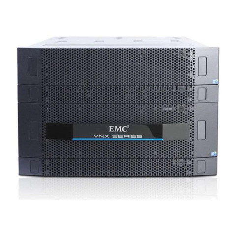
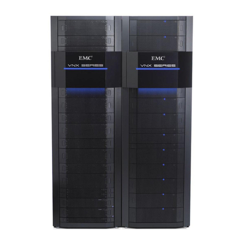
EMC EMC VNX VNX5200 User manual

EMCEMC®®VNXVNX®®
VNX5200VNX5200
™™
BlockBlock
Installation GuideInstallation Guide
P/N 300-999-786P/N 300-999-786
REV 02REV 02

11
Tasks to Complete after a VNX Installation
Two Sections have been added to the VNX w/ MCx installation. Performed the task below after theTwo Sections have been added to the VNX w/ MCx installation. Performed the task below after the
installation is complete.installation is complete.
Task 1:
Task 1: UpgrUpgrade ade ththe e VNX VNX OE OE to 05.3to 05.33.003.000.50.5.038 .038 or higor higherher
To resolve the unexpected reboot of the Storage Processor after ~80 days of To resolve the unexpected reboot of the Storage Processor after ~80 days of runtime upgrade the Blockruntime upgrade the Block
OE to 05.33.000.5.038 or higher.OE to 05.33.000.5.038 or higher.
ETA 175619:ETA 175619:
VNX: VNX systems will experience an unexpected reboot VNX: VNX systems will experience an unexpected reboot after ~80 days of after ~80 days of runtime.runtime.
If the VNX Block OE can not be upgraded then If the VNX Block OE can not be upgraded then reboot Storage Processor B.reboot Storage Processor B.
Task
Task 2: 2: Upgrade Upgrade Disk Drives require Disk Drives require a a firfirmware amware at the t the time of installatiotime of installatio nn
During disk drive qualification a variety of settings are changed for testing purposes.During disk drive qualification a variety of settings are changed for testing purposes.
Disk drives that are used with these settings for six (6) months will begin to degrade at Disk drives that are used with these settings for six (6) months will begin to degrade at an acceleratedan accelerated
rate and will eventually fail.rate and will eventually fail.
Refer to Knowledge Base Solution:Refer to Knowledge Base Solution: 0018033800180338
In the VNX Procedure Generator refer toIn the VNX Procedure Generator refer to
Service AlertService Alerts, Reference Documentss, Reference Documents, FC, FCOs, TSOs, TSEs and Parts Es and Parts Guides >Guides >
FCO FCO F0F012612614F14FO Shipped nO Shipped not Insot Ins talled Disk talled Disk Drive Firmware UpgrDrive Firmware Upgradeade
The drive part numbers that may be affected by this issue The drive part numbers that may be affected by this issue are shown in the table below:are shown in the table below:
Compass Drive Part NumbersCompass Drive Part Numbers
005049202005049202
005049203005049203
005049205005049205
005049206005049206
005049207005049207
005049250005049250
005049294005049294
005049295005049295
005049302005049302
005049577005049577
005049804005049804
005049820005049820
005049925005049925
005049926005049926
005049951005049951
005049956005049956
005050281005050281
005050282005050282

SeServicrvic e LAN Pe LAN Port Conort Connection nection for VNX with MCxfor VNX with MCx
CAUTION:CAUTION: Never connect a switch or hub between the two Service LAN Ports on anyNever connect a switch or hub between the two Service LAN Ports on any
VNXVNX5200, VNX5200, VNX5400, VNX5400, VNX5600, VNX5600, VNX5800 and 5800 and VNX7VNX7600 st600 st oragorage se systyst em.em.
Connect to only one Connect to only one of the VNX with Storage Processor MCx Service LAN of the VNX with Storage Processor MCx Service LAN Ports. Making a singlePorts. Making a single
connection to one Storage connection to one Storage Processor Service LAN Port will provide communicate to both StorageProcessor Service LAN Port will provide communicate to both Storage
Processors.Processors.
Use a single connection with a hub or a Use a single connection with a hub or a direct connection from your laptop to the Service LANdirect connection from your laptop to the Service LAN
port. Connecting both Service LAN ports to a Hub will cause a network storm and panic the port. Connecting both Service LAN ports to a Hub will cause a network storm and panic the array.array.
If this problem occurs, promptly remove the If this problem occurs, promptly remove the Ethernet cables. Reseat the Management Module ifEthernet cables. Reseat the Management Module if
the port appears not to function. The Management Modules are hot-swappable and may bethe port appears not to function. The Management Modules are hot-swappable and may be
removed and reseated without affecting the removed and reseated without affecting the array’s operation.array’s operation.
Figure 1
Figure 1 Service LAN PService LAN Port Connort Connection foection fo r VNX r VNX with with MCxMCx

VNVNX with MCX X with MCX LiLighght Bart Bar
IntroductionIntroduction
EMC REMC Rack Cabinack Cabinet:et:
Console: The door on the front of an Console: The door on the front of an EMC RACK that swings out of the way to allow access toEMC RACK that swings out of the way to allow access to
the disk drives. The Light Bar ithe disk drives. The Light Bar is part of the Console, the EMC Badge door. Opening s part of the Console, the EMC Badge door. Opening the doorthe door
provides access to VNX Bezels. The power to the Liprovides access to VNX Bezels. The power to the Light Bar is provided by a ght Bar is provided by a power supplypower supply
plugged into the PDU. A USB to USB cable provide a plugged into the PDU. A USB to USB cable provide a power connection between the powerpower connection between the power
supply and the Light Bar.supply and the Light Bar.

Customer Rack Cabinet:Customer Rack Cabinet:
Bezel Light Bar: Bezel Light Bar: A VNX with MCx bezel contains a Light bar. This is intended for use in non-EMCA VNX with MCx bezel contains a Light bar. This is intended for use in non-EMC
racks.racks.
PowePower Connectionsr Connections
The Blue Light Bar is The Blue Light Bar is powered by a power supply transformer assembly connected to the PDU.powered by a power supply transformer assembly connected to the PDU.
Figure 1
Figure 1 Light Light Bar Power ConneBar Power Connectorsctors

The DC power for the Bezel Light Bar is The DC power for the Bezel Light Bar is carried by cables from the power supplcarried by cables from the power supply through a racky through a rack
rail to the Light Bar power connector.rail to the Light Bar power connector.
Figure 2
Figure 2 AdAdjujuststblbl e Rail Set e Rail Set and and LiLighght Bar t Bar PowPower Caber Cablele
Figure 3Figure 3 Rail Set Internal Rail Set Internal CableCable
A USB to A USB to mini phono jack connects from tmini phono jack connects from the power supply to a jack locatehe power supply to a jack located on the back of thed on the back of the
right rail.right rail.

Figure 4
Figure 4 ReaRear Rail Power Connectior Rail Power Connectio nn
Figure 5
Figure 5 Rear Mini Phono ConnectionRear Mini Phono Connection
A pair of pogo pins on tA pair of pogo pins on the door makes contact whe door makes contact with a connector in the front ith a connector in the front of the rail to power tof the rail to power thehe
Light Bar located in the bezel.Light Bar located in the bezel.

Figure 6
Figure 6 Front Contact ConnectionFront Contact Connection
Figure 7Figure 7 Pogo Pin ConnectionPogo Pin Connection

Installation
Installation
Please note that there are modifications to the printed Please note that there are modifications to the printed File and Unified Installation File and Unified Installation guides whichguides which
one should be aware of.one should be aware of.
Under the PrepaUnder the Prepare your re your system:system:
Removing mini-rack components section, the updated text should now read:Removing mini-rack components section, the updated text should now read:
CAUTION:
CAUTION: On the left ganged rail, there is a blue light power connector protrudingOn the left ganged rail, there is a blue light power connector protruding
from the front whifrom the front whi ch goes througch goes through a hole in the front channel of the mini-h a hole in the front channel of the mini-rack.rack.
Figure 8
Figure 8 Light Bar power connectorLight Bar power connector
1. [ 1. [ ] ] Carefully remCarefully remove the ove the ganged rails ganged rails from tfrom the mini-rack he mini-rack by pulling by pulling each ganged each ganged rail out rail out fromfrom
the rear, then the front.the rear, then the front.
2. [ 2. [ ] ] Unscrew Unscrew the front the front and rear and rear screws and screws and remove the remove the ganged rails ganged rails from from the mini-rack.the mini-rack.
3. [ 3. [ ] ] Retain all tRetain all the removed he removed rails and scrrails and screws for ews for later assembly later assembly of the of the rails into the rails into the site rack.site rack.

Under the AsseUnder the Assemble componmble compon ents in your ents in your cabinet:cabinet:
Installing the Ganged Rails section, the Installing the Ganged Rails section, the updated text should now read:updated text should now read:
4. [ 4. [ ] ] Install the Install the ganged rail ganged rail into the into the appropriate location appropriate location in the in the site rack, site rack, for spacefor space
considerations find the lowest available space.considerations find the lowest available space.
Note:Note: The rails must be level The rails must be level front to back and with the companion rail front to back and with the companion rail left to right.left to right.
5. [ 5. [ ] ] Insert tInsert the right he right ganged rail ganged rail into the into the right side right side of the of the cabinet rack.cabinet rack.
6. [ 6. [ ] ] To hold the To hold the ganged rails ganged rails in place, insert in place, insert all the scall the screws (3 rews (3 front and front and 2 back) 2 back) previouslypreviously
removed from the ganged rails that were held removed from the ganged rails that were held in the mini-rack.in the mini-rack.
CAUTION:CAUTION: On the left ganged rail, there is a blue light power connector protrudingOn the left ganged rail, there is a blue light power connector protruding
from the front of the ganged rail which goes through a hole in the front post of thefrom the front of the ganged rail which goes through a hole in the front post of the
cabinet rack shown cabinet rack shown in Figure 8.in Figure 8.
7. [ 7. [ ] ] Carefully install Carefully install the left the left ganged rail ganged rail from tfrom the mini-rack he mini-rack by inserting by inserting the left the left ganged railganged rail
front first, then the rear.front first, then the rear.
8. [ 8. [ ] ] On the On the rear of rear of the left the left ganged rail, insert ganged rail, insert the gang rthe gang rail alignment pins ail alignment pins into the into the hole in thehole in the
back of the rack post.back of the rack post.
Figure 9
Figure 9 Gang Rail alignment pinsGang Rail alignment pins
9. [ 9. [ ] ] To hold the To hold the ganged rails ganged rails in place, insert in place, insert all the scall the screws (3 rews (3 front and front and 2 back) 2 back) previouslypreviously
removed from the ganged rails that were held removed from the ganged rails that were held in the mini-rack.in the mini-rack.
10. 10. [ [ ] ] Tighten Tighten the the screws.screws.
Ve
Verifyirifyi ng ng Proper OpeProper Operationration
Once the rail set is assembled in the rack cabinet and all connections have been made verifyOnce the rail set is assembled in the rack cabinet and all connections have been made verify
operation. With A/C applied to the PDU, the Light Bar will operation. With A/C applied to the PDU, the Light Bar will be lit with the Bezel ibe lit with the Bezel in place.n place.

If the Light Bar is not iIf the Light Bar is not illuminated reseat the cable connections. Use a lluminated reseat the cable connections. Use a DC volt meter to verify thatDC volt meter to verify that
a voltage is present at each a voltage is present at each connection point. A Light Bar that is connection point. A Light Bar that is not lit will not impact not lit will not impact systemsystem
operation. An unlit Light Bar is a operation. An unlit Light Bar is a cosmetic issue.cosmetic issue.
Installing VNX with MCx Components
Install the VNX with MCx components in the rack only Install the VNX with MCx components in the rack only if the Bezel Light Bar is if the Bezel Light Bar is operational.operational.
Replacing a rail set requires un-racking the system and is an off line event for an operationalReplacing a rail set requires un-racking the system and is an off line event for an operational
system.system.
Ordering Replacement Parts
The cable with light power connector and The cable with light power connector and rail assemble are not FRU parts so the rail assemble are not FRU parts so the Missing, WrongMissing, Wrong
and Damaged (MWD) process needs to be used and Damaged (MWD) process needs to be used to obtain replacement parts.to obtain replacement parts.
Table 1
Table 1 Light Bar Part NumbersLight Bar Part Numbers
Part NumberPart Number Console Light BarConsole Light Bar
UseUse
Bezel Light BarBezel Light Bar
UseUse
P/N 071-000-522 P/N 071-000-522 Power Supply TransformerPower Supply Transformer X X XX
P/N 038-003-941 P/N 038-003-941 USB 2.0 - USB Type A - USB TypeUSB 2.0 - USB Type A - USB Type XX
P/N 106-565-022 ganged rail kit numberP/N 106-565-022 ganged rail kit number XX
P/N 038-900-021 P/N 038-900-021 USB to mini Phono cableUSB to mini Phono cable XX

EMC VNX5200 Block Installation GuideEMC VNX5200 Block Installation Guide
22
Copyright © 2014 EMC Corporation. All rights reserved. Published in the USA.Copyright © 2014 EMC Corporation. All rights reserved. Published in the USA.
Published January, 2014Published January, 2014
EMC believes the information in this publication is accurate as of its publication date. The information is subject to change withoutEMC believes the information in this publication is accurate as of its publication date. The information is subject to change without
notice.notice.
The information in this publication is providThe information in this publication is provided as is. EMC Corporation makes no representations or warranties of ed as is. EMC Corporation makes no representations or warranties of any kind with respectany kind with respect
to the information in this publication, and specifically disclaims implied warranties of merchantability or fitness for a particularto the information in this publication, and specifically disclaims implied warranties of merchantability or fitness for a particular
purpose. Use, copying, and distribution of any EMC software described in this publication requires an applicable software license.purpose. Use, copying, and distribution of any EMC software described in this publication requires an applicable software license.
EMCEMC22, EMC, EMC Centera, EMC ControlCenter, EMC LifeLine, EMC , EMC, EMC Centera, EMC ControlCenter, EMC LifeLine, EMC OnCourse, EMC Proven, EMC Snap, EMC SourceOne, OnCourse, EMC Proven, EMC Snap, EMC SourceOne, EMC StorageEMC Storage
Administrator, Acartus, Access LogixAdministrator, Acartus, Access Logix, AdvantEdge, AlphaStor, ApplicationXtender, ArchiveXtender, Atmos, Authentica, Authentic, AdvantEdge, AlphaStor, ApplicationXtender, ArchiveXtender, Atmos, Authentica, Authentic
Problems, Automated Resource Manager, AutoStart, AutoSwap, AVALONidm, Avamar, Captiva, Catalog Solution, C-Clip, Celerra,Problems, Automated Resource Manager, AutoStart, AutoSwap, AVALONidm, Avamar, Captiva, Catalog Solution, C-Clip, Celerra,
Celerra Replicator, Centera, CenterStage, CentraStar, ClaimPack, ClaimsEditor, CLARiiON, ClientPak, Codebook CorrelationCelerra Replicator, Centera, CenterStage, CentraStar, ClaimPack, ClaimsEditor, CLARiiON, ClientPak, Codebook Correlation
Technology, Common Information Model, Configuration Intelligence, Connectrix, CopyCross, CopyPoint, CX, Dantz, Data Domain,Technology, Common Information Model, Configuration Intelligence, Connectrix, CopyCross, CopyPoint, CX, Dantz, Data Domain,
DatabaseXtender, Direct Matrix Architecture, DiskXtender, DiskXtender 2000, Document Sciences, Documentum, elnput, E-Lab,DatabaseXtender, Direct Matrix Architecture, DiskXtender, DiskXtender 2000, Document Sciences, Documentum, elnput, E-Lab,
EmailXaminer, EmailXtender, Enginuity, eRoom, Event Explorer, FarPoint, FirstPass, FLARE, FormWare, Geosynchrony, Global FileEmailXaminer, EmailXtender, Enginuity, eRoom, Event Explorer, FarPoint, FirstPass, FLARE, FormWare, Geosynchrony, Global File
Virtualization, Graphic Visualization, Greenplum, HighRoad, HomeBase, InfoMover, Infoscape, InputAccel, InputAccVirtualization, Graphic Visualization, Greenplum, HighRoad, HomeBase, InfoMover, Infoscape, InputAccel, InputAccel Express, Invista,el Express, Invista,
Ionix, ISIS, Max Retriever, MediaStor, MirrorView, Navisphere, NetWorker, OnAlert, OpenScale, PixTIonix, ISIS, Max Retriever, MediaStor, MirrorView, Navisphere, NetWorker, OnAlert, OpenScale, PixTools, Powerlink, PowerPath,ools, Powerlink, PowerPath,
PowerSnap, QuickScan, Rainfinity, RepliCare, RepliStor, ResourcePak, Retrospect, RSA, SafeLine, SAN Advisor, SAN Copy, SANPowerSnap, QuickScan, Rainfinity, RepliCare, RepliStor, ResourcePak, Retrospect, RSA, SafeLine, SAN Advisor, SAN Copy, SAN
Manager, Smarts, SnapImage, SnapSure, SnapView, Manager, Smarts, SnapImage, SnapSure, SnapView, SRDF, StorageScope, SupportMate, SymmAPI, SymmEnabler, Symmetrix,SRDF, StorageScope, SupportMate, SymmAPI, SymmEnabler, Symmetrix,
Symmetrix DMX, Symmetrix VMAX, TimeFinder, UltraFlex, UltraPoint, UltraScale, UnisSymmetrix DMX, Symmetrix VMAX, TimeFinder, UltraFlex, UltraPoint, UltraScale, Unisphere, Viewlets, Virtual Matrix, Virtual Matrixphere, Viewlets, Virtual Matrix, Virtual Matrix
Architecture, Virtual Provisioning, VisualSAN, VisualSRM, VMAX, VNX, VNXe, Voyence, VPLEX, VSAM-Assist, WebXtender, xPression,Architecture, Virtual Provisioning, VisualSAN, VisualSRM, VMAX, VNX, VNXe, Voyence, VPLEX, VSAM-Assist, WebXtender, xPression,
xPresso, YottaYotta, the EMC logo, and the RSA logo, are registered xPresso, YottaYotta, the EMC logo, and the RSA logo, are registered trademarks or trademarks of EMC trademarks or trademarks of EMC Corporation in the United StatesCorporation in the United States
and other countries. Vblock is a trademark of EMC Corporation in the United States.and other countries. Vblock is a trademark of EMC Corporation in the United States.
All other trademarks used herein All other trademarks used herein are the property of their respective owners.are the property of their respective owners.
For the most up-to-date regulatory document for your product line, go to the technical documentation and advisories section on theFor the most up-to-date regulatory document for your product line, go to the technical documentation and advisories section on the
EMC online support website.EMC online support website.

EMC VNX5200 Block Installation GuideEMC VNX5200 Block Installation Guide 33
CONTENTSCONTENTS
IntroductionIntroduction
Audience.......................Audience......................................................................................................................................................................................... 5........................ 5
Shipment Shipment MethodsMethods ....................................................................................................................................................................................................... 5. 5
Overview of Overview of installing installing an an EMC EMC cabinetcabinet .................................................................................................. .................................. 55
Overview of Overview of installing in installing in a customer a customer cabinetcabinet................................................................................................ .................. 66
Prepare your systemPrepare your system
Before Before you you beginbegin ............................................................................................................................................................................. ................................... 77
Site Site requirementsrequirements................................................................................................................................................................... 8............................... 8
Unpack your systemUnpack your system
UnpacUnpacking the king the Disk ProcDisk Processor Enclosessor Enclosure (DPE)ure (DPE) ............................................................................................ .......................... 99
DetacDetaching the DPE hing the DPE from the from the shipping material.shipping material.............................................................................................. ..................... 1111
Assemble cAssemble components in your cabinetomponents in your cabinet
Installing Installing railsrails ................................................................................................................................................................................................................ 14.... 14
Installing Installing the the DPE DPE rails......................rails............................................................................................................................ .............................. 1414
Installing Installing the the components...components............................................................................................................................................................. ................ 1515
Installing Installing the the disk disk processor processor enclosureenclosure ................................................................................................... ......................... 1515
Cable your systemCable your system
Attach Attach system system to to the networkthe network ....................................................................................................................................................... ............... 1919
Attaching stAttaching storage processors orage processors to to the networkthe network .................................................................................... ........................ 1919
Power upPower up
Before Before you you power power upup ................................................................................................................................................................... ............................. 2121
Connecting Connecting or or verifying poverifying power wer cablescables .......................................................................................................... .................................... 2121
Verifying Verifying system system statusstatus ................................................................................................................................................................... 22..................... 22
Add additional stAdd additional storageorage
Disk-array Disk-array enclosure enclosure typestypes ......................................................................................................................................................... 23..................... 23
Assembling Assembling DAEsDAEs ................................................................................................................................................................................................... 25....... 25
Install Install DAE DAE railsrails ................................................................................................................................................................................................... 28. 28
Install Install the the DAE......DAE.......................................................................................................................................................................... 29........................ 29
Connect SAS Connect SAS DPE and DPE and DAE cables.........................DAE cables............................................................................................................. ........ 3232
Power Power up up DAEsDAEs .............................................................................................................................................................................................................. 35.... 35
Verify Verify DAE DAE statusstatus............................................................................................................................................................................ ................................ 3636
Verify 3U, Verify 3U, 15 3.5” 15 3.5” drive DAE drive DAE status............status...................................................................................................... ........................ 3636

44 EMC VNX5200 Block Installation GuideEMC VNX5200 Block Installation Guide
Verify 2U, Verify 2U, 25 2.5” 25 2.5” drive DAE drive DAE status............status...................................................................................................... ........................ 3737
Verify Verify 4U, 4U, 60 60 drive DAE drive DAE statusstatus ................................................................................................................................................. 37....... 37
SetupSetup
Connect Connect a a management management stationstation ........................................................................................................................................................... ..... 3939
Initialize Initialize your your storage storage systemsystem ......................................................................................................................................................... ............. 3939
Downloading the Unisphere Downloading the Unisphere Storage System Initialization Storage System Initialization Wizard...................Wizard....................... .... 3939
Update the Update the storage syststorage system software and registem software and register your syster your systemem .................................. .................................. 4040
Downloading Downloading USM USM documentationdocumentation ........................................................................................................................................ 40.. 40
Downloading Downloading Unisphere Service Unisphere Service Manager.........Manager........................................................................................... .................. 4040
Downloading the latest version of the VNX operating environment softwareDownloading the latest version of the VNX operating environment software
(optional)(optional) ............................................................................................................................................................................................................... ....... 4141
Registering your Registering your system for system for service with service with your service your service providerprovider ............................ ............................ 4141
Check Check system system healthhealth ........................................................................................................................................................... 41......................... 41
Check Check system system events....events...................................................................................................................................................................... ...................... 4141
InsInstall tall ESRS and ESRS and configure Cconfigure ConnectHomeonnectHome .................................................................................................. ................................ 4242
Downloading ESRS documentation Downloading ESRS documentation and setting up and setting up ESRS..................ESRS..................................... ................... 4242
Configure Configure servers fservers for or VNX VNX systemssystems ................................................................................................................................................. 42..... 42
Provision Provision storagestorage ......................................................................................................................................................................... 42................................. 42
Attach Attach bezelsbezels ............................................................................................................................................................................................................ 43.......... 43
Planning WorksheetsPlanning Worksheets
VNX VNX Block Block Configuration Configuration WorksheetWorksheet ............................................................................................................................................. 45..... 45
ESRS ESRS Worksheet..................Worksheet............................................................................................................................................................................. 48............... 48

IntroductionIntroduction 55
IntroductionIntroduction
AudienceAudience
Although your VNX system is Although your VNX system is customer-inscustomer-installable, EMC recommends that the installation betallable, EMC recommends that the installation be
performed by someone who has performed by someone who has a general background in information technologya general background in information technology. While . While priorprior
training is not training is not required, customerrequired, customers who s who successuccessfully installed this product were trained as:sfully installed this product were trained as:
◆◆ EMC Proven ProfessionalsEMC Proven Professionals
◆◆ Microsoft Certified Microsoft Certified TecTechnology Specialistshnology Specialists
◆◆ Cisco Certified Network Cisco Certified Network AssociatesAssociates
◆◆ CompTIA A+ certified CompTIA A+ certified techniciantechnicianss
YouYour service pror service provider offervider offers a variety of ins a variety of installation and impstallation and implementation serviclementation services designed es designed toto
assist you in putting your VNX system into production as quickly and efficiently as possible.assist you in putting your VNX system into production as quickly and efficiently as possible.
Contact your sales representative to take advantage of these service offerings.Contact your sales representative to take advantage of these service offerings.
Shipment MethodsShipment Methods
There are two ways in which the There are two ways in which the product is packed and shipped to you. It will be product is packed and shipped to you. It will be shippedshipped
completely-installed and cabled in an EMC cabinet or it will be shipped in multiple boxes forcompletely-installed and cabled in an EMC cabinet or it will be shipped in multiple boxes for
installation into a installation into a customer-pcustomer-provided cabinet.rovided cabinet.
Overview of installing an EMC cabinetOverview of installing an EMC cabinet
If your system was shipped in an EMC cabinet, the installation process involves the followingIf your system was shipped in an EMC cabinet, the installation process involves the following
steps:steps:
1.1. ReaRead and compd and complete the plete the prerrerequiequisite tasite tasks listsks listed ined in “Before
“Before you begin” oyou begin” on pagen page 77..
2.2. Unpack the Unpack the shipping boshipping boxes and vxes and verify the shipperify the shipping conteing contents from the nts from the packing packing instructions instructions onon
the outside of the the outside of the box as described inbox as described in “Unpacking the Disk Processor Enclosure (DPE)” on
“Unpacking the Disk Processor Enclosure (DPE)” on
papagege 99..
3.3. Verify Verify the cabling the cabling and connand connect the systect the system to yoem to your networur network as desck as described inribed in “Cable your
“Cable your
systesystem” on pagm” on pagee1919..
4.4. Power up Power up your sysyour system and verify thtem and verify that the system at the system powered powered up correup correctly by cctly by checking the hecking the LEDs ofLEDs of
the disk processor enclosure (DPE). This is described inthe disk processor enclosure (DPE). This is described in “Pow
“Power up” on pager up” on pagee2121..
5.5. CoCompmpletlete the te the taskasks liss listed ited inn “Setu
“Setup” on pap” on pagege 3939..

66 EMC VNX5200 Block Installation GuideEMC VNX5200 Block Installation Guide
Overview of installing in a Overview of installing in a customer cabinetcustomer cabinet
If your system was If your system was shipped to be shipped to be installed in your own cabinet, the installed in your own cabinet, the installation procesinstallation process involvess involves
the following:the following:
1.1. ReaRead and compd and complete the plete the prerrerequiequisite tasite tasks listsks listed ined in “Before
“Before you begin” oyou begin” on pagen page 77..
2.2. Unpack Unpack the shipping the shipping boxes boxes and verand verify the shipify the shipping conping contents as tents as described described inin “Unpack your
“Unpack your
systesystem” on pm” on pageage 99..
3.3. Remove Remove shipping conshipping container ctainer contents and ontents and assemble assemble the componthe components in yents in your cabineour cabinet ast as
described indescribed in “Assemble comp
“Assemble components in your cabonents in your cabinet” on pageinet” on page 1313..
4.4. CabCable yle your our systsystem as em as descdescriberibed ind in “Cable y
“Cable your system” on our system” on pagepage 1919..
5.5. Power up Power up your systyour system by conem by connecting power cnecting power cables, and theables, and then verify that the syn verify that the system powerestem poweredd
up correctly by checking the LEDs of the DPE as up correctly by checking the LEDs of the DPE as described indescribed in “Pow
“Power up” on pager up” on pagee2121..
6.6. OptionallyOptionally, you can , you can add a disk arradd a disk array enclosure ay enclosure (DAE), p(DAE), power it up anower it up and then verify that the d then verify that the DAEDAE
powered up correctly by checking the DAE LED status as described inpowered up correctly by checking the DAE LED status as described in “Add additional storage”
“Add additional storage”
on pon pageage 2323..
7.7. CoCompmpletlete the te the taskasks liss listed ited inn “Set
“Setup” on pup” on pageage 3939..

Prepare your systemPrepare your system 77
Prepare your systemPrepare your system
Use the Before you begin checklist to help you determine what you need to install for your system.Use the Before you begin checklist to help you determine what you need to install for your system.
Before you beginBefore you begin
TTablablee
Before you beginBefore you begin
CCoommpplleettee TTaasskk CCoommmmeennttss
❏❏ 1.1. SeSetutup a prp a prododucuct sut supppporort act acccouountnt.. If yIf you dou do noo not alt alrereadady hay have a ve a PrPrododucuct St Supuppoport art accccouountnt, g, goo
toto https://Support.EMC.com
https://Support.EMC.comto set one up.to set one up.
You will need a support accYou will need a support account for access ount for access to the latestto the latest
documentation and troubleshooting information, onlinedocumentation and troubleshooting information, online
chat, installation and maintenance videos, utilities andchat, installation and maintenance videos, utilities and
wizards.wizards.
❏❏ 2.2. Complete the Complete the VNX Block VNX Block ConfigurationConfiguration
Worksheet and the ESRS Worksheet.Worksheet and the ESRS Worksheet.
These worksheets are provided at the end of thisThese worksheets are provided at the end of this
document.document.
To download additional worksheets:To download additional worksheets:
•• Go toGo to https://Support.EMC.com
https://Support.EMC.com, select, select
VNX5200VNX5200
, and, and
then download the appropriate worksheets.then download the appropriate worksheets.
❏❏ 33. P. Prreeppaarre e ssiittee.. FFoor r rreessoouurrcce e rreeqquuiirreemmeennttss, , ggo o ttoo T
Tablablee2 o2 on pn pageage 88..
❏❏ 4.4. DownlDownload and print the VNX plannoad and print the VNX planneded
power up and power down procedures.power up and power down procedures.
Planned power down of VNX systems utilize UnPlanned power down of VNX systems utilize Unisphereisphere
since there are no hardware Off switches. All VNX powersince there are no hardware Off switches. All VNX power
up and power down procedures are available atup and power down procedures are available at
https://mydocs.emc.com/VNX/
https://mydocs.emc.com/VNX/. They are also available. They are also available
in thein the VNX System Operations GuideVNX System Operations Guide..
❏❏ 5.5. Download aDownload additional Vdditional VNX instNX installationallation
documentation (when appropriate).documentation (when appropriate).
EMC provides additional documentation for installationEMC provides additional documentation for installation
of certain VNX systems, including:of certain VNX systems, including:
•• NENEBS sBS sysystetemsms
•• DenDense-rse-racack k syssystemtemss
To download this documentation, go toTo download this documentation, go to
https://Support.EMC.com
https://Support.EMC.com, select, select
VNX5200VNX5200
>>
DocumentationDocumentation
..
❏❏ 6.6. CoConsunsult VNX dolt VNX documcumententatiation (opon (optiotionalnal).). •• If you arIf you are unfae unfamilmiliar witiar with the VNX syh the VNX syststem arcem archithitectecture,ure,
download and review thedownload and review the VNX5200 HardwareVNX5200 Hardware
Information GuideInformation Guidebefore you begin the installation.before you begin the installation.
Go toGo to https://Support.EMC.com
https://Support.EMC.comand selectand select
VNX5200VNX5200
>>
DocumentationDocumentation
>>
Manuals and GuidesManuals and Guides
>>
VNX5200VNX5200
Hardware Information GuideHardware Information Guide
..
•• If you want to generate documentation specific to yourIf you want to generate documentation specific to your
system configuration, including to configure servers,system configuration, including to configure servers,
update software, or add and replace hardware, go toupdate software, or add and replace hardware, go to
https://mydocs.emc.com/VNX/
https://mydocs.emc.com/VNX/..

88 EMC VNX5200 Block Installation GuideEMC VNX5200 Block Installation Guide
Site requirementsSite requirements
TTablablee 22
Site RequirementsSite Requirements
AreaArea RequirementRequirement
PowerPower AC Power: For high availability, at least two AC circuits are required.AC Power: For high availability, at least two AC circuits are required.
VNX models with the 1100 W power supply (VNX52DPxxx/VNXB52DPxxx] require atVNX models with the 1100 W power supply (VNX52DPxxx/VNXB52DPxxx] require at
least two 200-240 V AC circuits.least two 200-240 V AC circuits.
VNX models with the 800 W power supply (VNX52VPxxx) require at least two 100-240VNX models with the 800 W power supply (VNX52VPxxx) require at least two 100-240
V AC circuits. These models have specific power limits.V AC circuits. These models have specific power limits.
See theSee the VNX5200 Hardware Information GuideVNX5200 Hardware Information Guide..
For full power specifications, go toFor full power specifications, go to Mydocs.emc.com
Mydocs.emc.com and selectand select
View technicalView technical
specificationsspecifications
under the About VNX section.under the About VNX section.
NNeettwwoorrkk TTwwo o 11--GGiiggaabbiit Et Etthheerrnneet mt maannaaggeemmeennt ct coonnnneeccttiioonns as annd td twwo o ccuussttoommeerr--ssuupppplliieed Cd CAATT55ee
or better cables.or better cables.
SSppaaccee CCaabbiinneet t vveerrttiiccaal l ssppaaccee::
•• 3U (unit) (5.23U (unit) (5.25 inches, 13.5 inches, 13.3 cm) for disk proc3 cm) for disk processor encessor enclosurlosure (DPE)e (DPE)
•• For eaFor each och optional ptional DAE, eDAE, either 2Uither 2U, 3U, o, 3U, or 4U.r 4U.
TToooollss SSllootttteed d oor r PPhhiilllliipps s ssccrreewwddrriivveer r
MaMananagegemement nt StStatatioionn A WA Winindodowsws-b-basased ced comompuputeter tr to ro run un ththe ine inititiaialilizazatitionon, m, maiaintntenenanancece, a, and nd mamananagegemementnt
tools with:tools with:
•• Minimum sMinimum screen rescreen resolutioolution of 1280 x 800 ann of 1280 x 800 and 256 cold 256 colorsors
•• At leAt least ast 500 MB o500 MB of frf free spaee spacece
•• ConnConnection on saection on same LAN subnet as your sysme LAN subnet as your system if you will use it to initiatem if you will use it to initialize thelize the
systemsystem
•• WindoWindows Dows Domain Cmain Controontroller rller recomecommendedmended
•• SMTP servSMTP server network cer network connectonnection to the VNX52ion to the VNX5200 and the manag00 and the management hosement hostt
•• JJRREE**
•• BrowsBrowser* (Inteer* (Internet Explrnet Explorer, orer, MozilMozilla Firela Firefox)fox)
*Supported versions are listed in the release notes.*Supported versions are listed in the release notes.
NeNetwtworork ink infoformrmatatioionn ThThe me mananagagememenent pt porort at and nd lologigin in infnforormamatition on in in ththe Pe Plalannnnining Wg Wororksksheheetets os of tf thihis is insnstatallll
guide. This information includes:guide. This information includes:
•• A static A static IP address foIP address for each r each storage procstorage processor in the essor in the system (for system (for example,example,
123.45.6.7)123.45.6.7)
•• The IPv6 globaThe IPv6 global prefix and gl prefix and gateway fateway for each SP ior each SP if your netwof your network suppork supports the IPv6rts the IPv6
Internet Protocol and you want to manually configure IPv6 for the Internet Protocol and you want to manually configure IPv6 for the managementmanagement
portsports
•• The subnet maThe subnet mask of the LAN to whisk of the LAN to which the sysch the system is cotem is connectednnected
•• The defauThe default gatewalt gateway addresy address of the LAN to whics of the LAN to which the systeh the system is connem is connectedcted

Unpack your systemUnpack your system 99
Unpack your systemUnpack your system
Unpack and install the DPE first. Other storage (DAEs) will be unpacked, assembled, and cabledUnpack and install the DPE first. Other storage (DAEs) will be unpacked, assembled, and cabled
later.later.
Unpacking the Disk Processor Enclosure (DPE)Unpacking the Disk Processor Enclosure (DPE)
You You will have rwill have received yeceived your system eour system either fully asither fully assembled and sembled and cabled in an cabled in an EMC cabinet, EMC cabinet, or inor in
shipping boxes to be unpacked and installed into your own cabinet.shipping boxes to be unpacked and installed into your own cabinet.
Note:Note:
If your system includes the use of If your system includes the use of 4U DAEs, they are not customer-installab4U DAEs, they are not customer-installable. They willle. They will
arrive either installed in an EMC cabinet fully assembled or in separate shipping boxes and willarrive either installed in an EMC cabinet fully assembled or in separate shipping boxes and will
need to be installed by service personnel.need to be installed by service personnel.
If your system was shipped fully assembled and cabled in an EMC If your system was shipped fully assembled and cabled in an EMC cabinet:cabinet:
1.1. FollFollow the unow the unpacpacking inking instrucstructiontions on the outss on the outside of the boide of the box.x.
2.2. Go Go didirerectctly ly toto “Cable y
“Cable your system” on our system” on pagepage 1919of this installation guide to verify the cabling.of this installation guide to verify the cabling.
If your system was shipped in If your system was shipped in separate boxeseparate boxes and needs s and needs to be assembled in your own to be assembled in your own cabinet:cabinet:
1.1. Verify thVerify that you have rat you have received aleceived all of the DPE col of the DPE components, includmponents, including cableing cables, bezel, rs, bezel, rail kit, andail kit, and
mounting screws.mounting screws. Fig
Figururee1 o1 on pn pageage 1010shows the shows the shipping contents.shipping contents.

1010 EMC VNX5200 Block Installation GuideEMC VNX5200 Block Installation Guide
FiFigurguree 11
DPE container contentsDPE container contents
Disk processor enclosure
(DPE)(DPE)
1 per DPE1 per DPE
Service cableService cable
2 per DPE2 per DPE
Power cablesPower cables
Documentation kit, including InstallationDocumentation kit, including Installation
Guide, environmental information, andGuide, environmental information, and
sheets of cable labels.sheets of cable labels.
FrontFront Disk-processDisk-processor or enclosureenclosure (Jetfire)(Jetfire)
AABB
SPSP
SPSP
FrontFront
Will MaketheArray UnusableWill MaketheArray Unusable
Caution: Array Software on drives 0-3. Removing or relocating themCaution: Array S oftware on drives 0-3. Removing or relocating them
0101
0101
RearRear
44
AdjustablAdjustable rail kite rail kit
MountingMounting
screwsscrews
4 SAS cables4 SAS cables
BezelBezel
AACC
DDCC
!!
1 1 001 1 00
X4X4
AACC
DDCC
!!
X4X4 X4X4
X4X4
Table of contents
Other EMC Network Hardware manuals