emcotherme KXs User manual

emcobad
emcobau emcoklima
emcothermcontrol technology
Operating Instructions · Part 2.1.4
214OI_control_technology_GB_id8506280_0890112.pdf 1 12.01.2009 12:11:39 Uhr

contents
Important Information and User Instructions1 .....................4
General introduction. ................................................................................................
Why you should read this manual. .......................................................................
Diagrams and descriptions in this manual. ........................................................
The meanings of symbols and warning instructions.
used in this manual...................................................................................................
Supporting documents. ............................................................................................
Intended use. ...............................................................................................................
Improper use. ................................................................................................................
Legal information, copyrights. ................................................................................
Warranty, guarantee and liability. ........................................................................
Version and revision level in this manual. ..........................................................
Manufacturer’s address. ...........................................................................................
Safety Information2 ................................................................9
Safety-conscious operation. ....................................................................................
Qualifications of personnel. ...................................................................................
User due diligence. ...................................................................................................
emcotherm3 Components for
Individual Room Temperature Control ................................ 11
General instructions about the installation site for.
emcotherm individual room temperature control components...............
Recommended use for emcotherm control technology. .............................
Room thermostat type. emco RT..........................................................................
Speed controller type. emco DZR ........................................................................
Electronic climate controller. emcotronic II......................................................
Programmable room thermostat. emcotime II..............................................
emcotherm –4 Electrical Connection Diagrams................... 47
Circuitry KXs, KMS, K-K, K-K, KIQ-KIQ with.
room thermostat or emcotime II .......................................................................
Circuitry KQs and KQ - KQ with.
room thermostat and electronic potentiometer .........................................
Circuitry KQs and KQ - KQ with.
room thermostat and fixed speed module.....................................................
Circuitry KQs and KQ - KQ with. emcotronic II............................................
Circuitry KQs and KQ - KQ to the.
building automation control (DDC) ...................................................................
Circuitry KQK (-pipe) with.
room thermostat and electronic potentiometer..........................................
Circuitry KQK (- pipe) with.
room thermostat and fixed speed module.....................................................
Circuitry KQK (- pipe) with. emcotronic II.......................................................
Circuitry connection KQK (- pipe) to the.
building automation control (DDC) ...................................................................
214OI_control_technology_GB_id8506280_0890112.pdf 2 12.01.2009 12:11:41 Uhr

Circuitry KQK (- pipe) with. emcotronic II ......................................................
Circuitry connection KQK (- pipe) to the.
building automation control (DDC) ...................................................................
Circuitry KQKL (- pipe) with.
room thermostat and electronic potentiometer..........................................
Circuitry KQKL (- pipe) with.
room thermostat and fixed speed module.....................................................
Circuitry KQKL (- pipe) with. emcotronic II....................................................
Circuitry connection KQKL (- pipe) to.
building automation control (DDC) ...................................................................
Circuitry KQKL (- pipe) with. emcotronic II ....................................................
Circuitry connection KQKL (- pipe) to.
building automation control (DDC) ..................................................................
Circuitry BKQ (- pipe) with.
room thermostat and electronic potentiometer..........................................
Circuitry BKQ (- pipe) with.
room thermostat and fixed speed module.....................................................
Circuitry BKQ (- pipe) with. emcotronic II......................................................
Circuitry BKQ (- pipe) to building automation control. (DDC) ................
Circuitry BKQ (- pipe) with. emcotronic II ......................................................
Circuitry BKQ (- pipe) to building automation control. (DDC) ...............
5 Upstream Face Equipment
(emcotherm Control Components).................................... 70
General safety advice. .............................................................................................
Overview of upstream face equipment. ...........................................................
emco. thermostat valve type TVU ......................................................................
thermostat valve types TVU -V -E and TUV -V -D. ..........................................
emco. universal detentor valve type UFV.........................................................
emco. actuator type TS ..........................................................................................
emco. thermostat with remote adjuster type TK/F......................................
6 Conformity .......................................................................... 85
7 Replacement Parts.............................................................. 85
8 Taking out of Operation, Disassembly and Disposal........ 85
214OI_control_technology_GB_id8506280_0890112.pdf 3 12.01.2009 12:11:41 Uhr

emcotherm control technology
Subject to technical changes without prior notice! June
Important Information and User Instructions1
General introduction1.1
emcotherm control technology offers products that are individually
harmonised to the needs of the convector market. This technology
has been developed in an environmentally-friendly and effective way
according to the latest state of technology.
Centralised and decentralised controlled and set switching functions
allow emcotherm control technology to be matched perfectly to the
product interfaces of leading manufacturers of convectors.
emcotherm control technology primarily consists of the following
components:
Connection box with integrated control board→
In emcotherm floor convectors, the connection box is installed in→
the convector at the factory and is ready for connection (see chapter
“Electrical Connection“ in the accompanying emcotherm convector
manual)
Components for individual room temperature control (see chapter →
in this manual)
Accessories for control components (see chapter in this manual)→
Recommended uses and operation of emcotherm control components
can be found on the following pages of this manual.
Why you should read this manual1.2
This manual has been prepared to the best of our knowledge. In
particular this manual describes the areas of use, operation and
proper installation of the various emcotherm control components. It
should make the operator, user and maintenance personnel familiar
with the setup, functions, operation and maintenance as well as the
safety factors of these control components. This manual also contains
important information and descriptions for professional fitting and
installation of the emcotherm control components when used with
emcotherm convectors. It is therefore mainly intended for trained and
qualified personnel.
Please keep this manual in a safe place, so that you can refer to it
whenever necessary. Also be sure to pass this user information on to
subsequent owners.
214OI_control_technology_GB_id8506280_0890112.pdf 4 12.01.2009 12:11:42 Uhr
emcotherm control technology
Subject to technical changes without prior notice! June
Diagrams and descriptions in this manual1.3
Chapter and section titles, important information and functions are→
displayed in bold print.
Danger, warning and information notices are structured as follows:→
PIKTOGRAMME
+ SIGNAL WORD
SIGNAL WORD
Description of the danger or information. Particularly important texts
and keywords are displayed in bold type.
Possible implications and effects of non-observance are indented→
and in bold type.
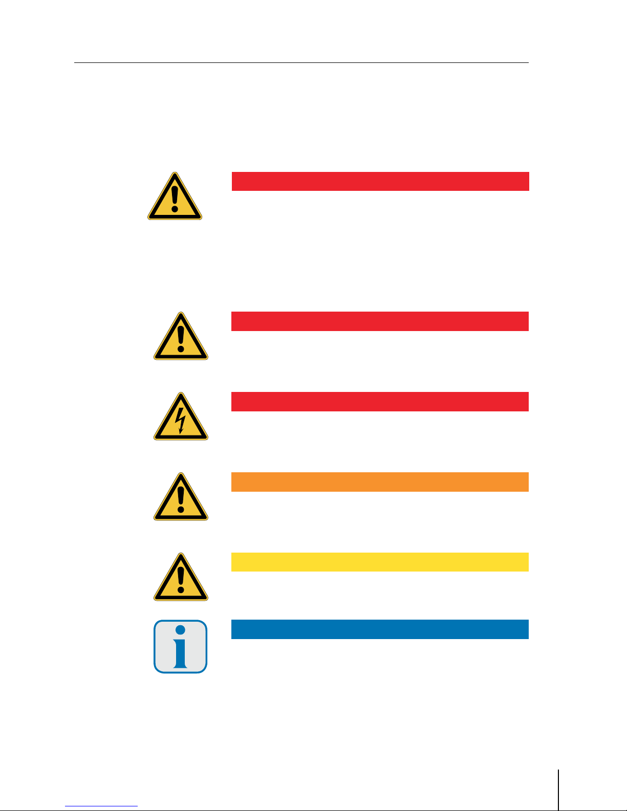
The meanings of symbols and warning instructions used in this manual1.4
The meanings of the individual warnings and symbols are explained in
the following and are classified into danger categories.
DANGER !
DANGER !
Identifies an immediate hazard with a high risk to the life and health of
persons.
Non-observance of this sign can result in death or serious bodily→
injury.
DANGER !
DANGER !
Identifies an immediate hazard of electrocution with a high risk to the
life and health of persons.
Non-observance of this sign can result in death or serious bodily→
injury.
WARNING !
WARNING !
Identifies a possible hazard with an moderate risk to the life and health
of persons..
Non-observance of this sign can result in death or serious bodily→
injury.
CAUTION !
CAUTION !
Identifies a danger with low risk or a potentially dangerous situation.
Non-observance of this sign can result in slight or moderate bodily→
injury or material damages.
ATTENTION !
ATTENTION !
Provides tips and valuable information to the user for proper use of the
products..
Non-observance of this sign can result in disruptions or have an→
effect on the surroundings.
In some chapters, internationally used and self-explanatory danger
symbols will be used.
214OI_control_technology_GB_id8506280_0890112.pdf 5 12.01.2009 12:11:42 Uhr
emcotherm control technology
Subject to technical changes without prior notice! June
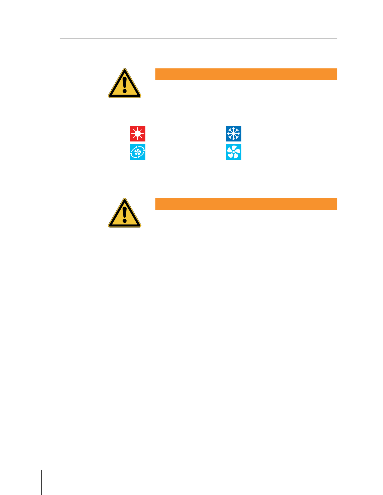
WARNING !
WARNING !
Please note that a symbol or pictogramme can never take the place of
a text or instruction! Always be sure to read each text or instruction in
full!
Other symbols used in this manual:1.4.1
= Heating = Cooling
= Secondary air = Ventilation
(external fresh air connection)
Supporting documents1.5
WARNING !
WARNING !
Warning !
This manual only contains partial documentation and technical
instructions for the emcotherm control components and accessories.
The use of the components described in this manual as well as their
operation, fitting and installation should always be regarded together
and in connection with the respective convector.
Please always carefully read the manual for the convector and follow
all safety, operation and information instructions contained therein.
Intended use1.6
emcotherm control components have been manufactured according
to the latest technology and recognised safety-related regulations, in
accordance with norms and standards as listed in the technical data
section of this manual. However, improper use can result in serious
danger to the user or third parties as well as damage the control
components and/or any devices connected to them.
emcotherm control components may only be used in a technically
correct condition, in compliance with safety and precautionary
measures, according to their intended use and in compliance with
all operating, fitting, installation and maintenance instructions! Any
errors or failures, that could affect safe operation must be taken care of
immediately!
214OI_control_technology_GB_id8506280_0890112.pdf 6 12.01.2009 12:11:42 Uhr
emcotherm control technology
Subject to technical changes without prior notice! June
Furthermore, it is imperative to adhere to all general safety-related
conditions at the installation site as well as all relevant valid directives
for the application, such as rules for accident prevention et al.
Regulations and possible uses of the various emcotherm control
components are documented in this manual as well as in the manual of
the respective convector.
In general, all emcotherm control components are to be used only in
enclosed interiors (e.g. residential, commercial or showroom space)
with central European conditions
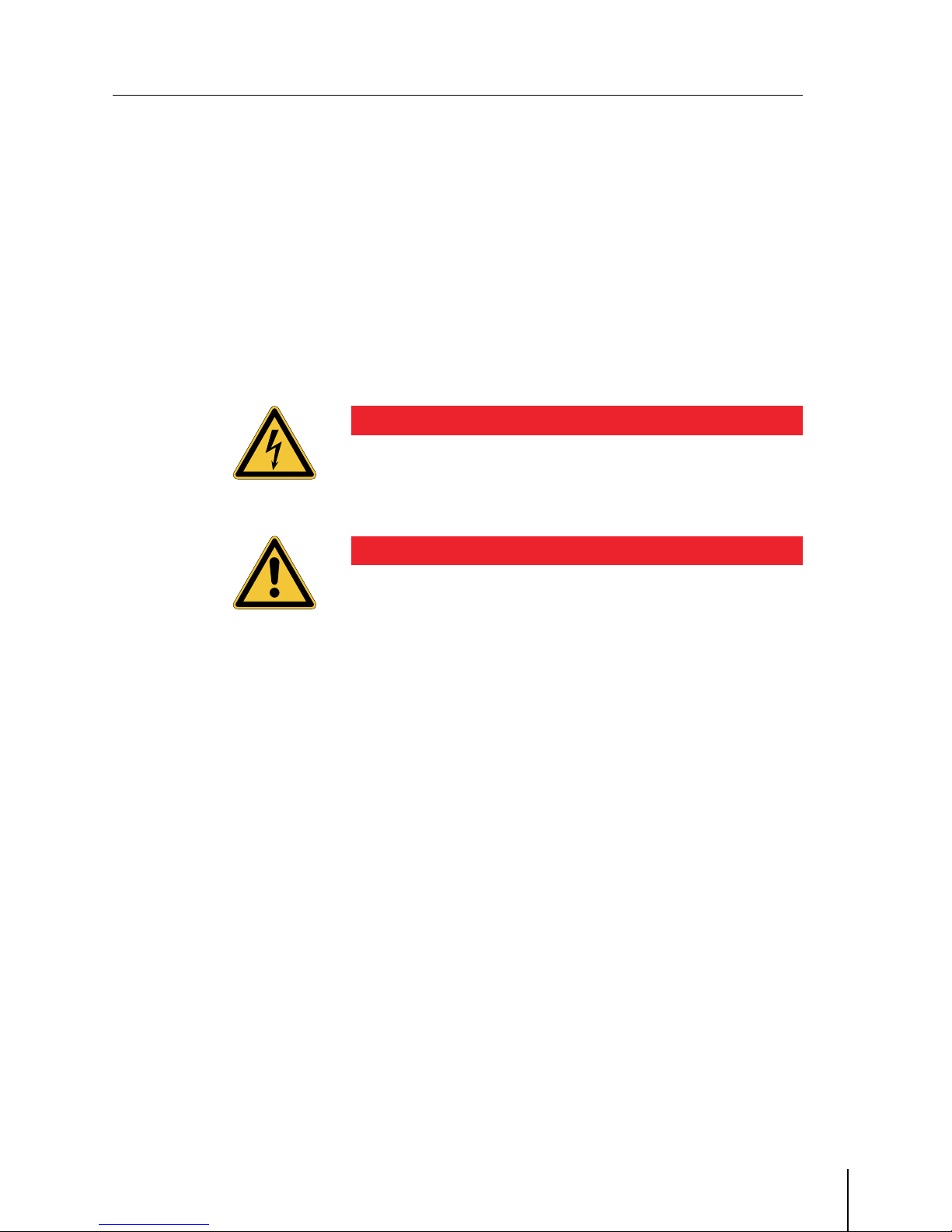
DANGER !
DANGER !
Use in damp areas (e.g. swimming pools) or outside of enclosed
buildings is not intended and therefore not allowed.
Non-observance of this information can lead to short circuits in the→
electrical installation, as well as to death or serious bodily injury.
DANGER !
DANGER !
emcotherm control components do not meet the requirements of the
ATEX Directive; their use and operation in potentially explosive areas is
forbidden.
Failure to comply with this information can lead to explosions,→
as well as to death or serious bodily injury.
Improper use1.7
Any use of the control components that differs from the use described
in this manual is considered improper use. The manufacturer is NOT
responsible for any personal and property damages resulting from
improper use. Any such damage is the sole responsibility of the user
Legal information, copyrights1.8
This manual may not be electronically or mechanically copied,
distributed, changed or transmitted, translated or otherwise used
without the prior approval of emco Bau- und Klimatechnik GmbH & Co.
KG.
emco are not liable for damage resulting from non compliance or
partial non compliance with this manual. Handing over this manual
does not justify any claim to a licence or use.
214OI_control_technology_GB_id8506280_0890112.pdf 7 12.01.2009 12:11:42 Uhr

emcotherm control technology
Subject to technical changes without prior notice! June
Warranty, guarantee and liability1.9
The extent and duration of the guarantee are based on the respective
contract as well as the general Terms and Conditions of emco Bau- und
Klimatechnik GmbH & Co. KG.
Guarantee and liability claims are generally ruled out if damage can be
proven to be the result of incorrect installation, improper use or force
majeure.
The information provided in this manual has been carefully checked,
but liability is not accepted for any mistakes.
Versions and issues of this manual1.10
The version and issue of this manual are those of February .
We herewith expressly point out that descriptions, figures, charts and
performance values are non-binding information. emco serves the right
to make technical changes to the product or its components at any
time in order to improve safety, reliablity, function and design.
Manufacturer’s address1.11
EMCO Bau- und Klimatechnik GmbH & Co. KG
Geschäftsbereich Klimatechnik
Breslauer Straße -
D- Lingen (Ems)
e-mail: klima@emco.de
Internet: www.emco-klima.de
214OI_control_technology_GB_id8506280_0890112.pdf 8 12.01.2009 12:11:42 Uhr

emcotherm control technology
Subject to technical changes without prior notice! June
Safety Information2
Safety-conscious operation2.1
The highest level of safety and a high standard of quality are a matter
of course to us, which is why all emcotherm control components have
been developed, manufactured and tested according to the latest
applicable norms, standards and directives.
Safe operation of emcotherm control components and the devices
connected to them can only be guaranteed if the control components
and connected devices are in a technically correct condition and are
used in a safe and aware manner according to their intended use!
For your own safety, we strongly recommend that you read and adhere
to all safety instructions in this manual as well as those in the manual
of connected devices (convector) before fitting, installing, operating
and using the emcotherm control components.
Personnel qualification2.2
In normal operating situations it is assumed that both emcotherm
control components and connected devices (convectors) are properly
fitted, electrically installed and ready for operation. Basic operation
and setting functions of the emcotherm control components can
be executed by semi-skilled and trained personnel according to the
directions in this manual.
All activities that go beyond simple operating and adjusting functions
such as fitting, installation, error / fault remedying and repairs must be
carried out by trained and qualified specialists.
DANGER !
DANGER !
All electrical installations, connecting, and disconnecting the
emcotherm control components may only be carried out by electrical
specialists* in compliance with the electrotechnical regulations.
* Definition of an electrical specialist as per:
Regulations for the Prevention of Industrial Accidents- Electrical
Systems, BGV A and
German Low Voltage Connection Ordinance (NAV)
Non-observance of this information can lead to death or serious→
bodily injury.
Competency and authorisation of personnel are to be determined by
the operator.
214OI_control_technology_GB_id8506280_0890112.pdf 9 12.01.2009 12:11:42 Uhr

emcotherm control technology
Subject to technical changes without prior notice! June
User due diligence2.3
The operator of the system is obligated to ensure that
emcotherm control components are used only as intended and are→
in impeccable and working condition.
Only trained specialists carry out fitting, electrical installations,→
settings and/or changes to the default values, error / fault
clearance and/or repairs.
This manual is always kept at the place of use and where necessary→
can be accessed by the user and other specialists for reference to
ensure appropriate operation and use of the components for
individual room temperature control
WARNING !
WARNING !
For safety reasons, no arbitrary and unauthorised changes may be
made to the emcotherm control components.
Non-observance of this information can lead to death, serious→
bodily injury or result in damage to the items.
214OI_control_technology_GB_id8506280_0890112.pdf 10 12.01.2009 12:11:42 Uhr
emcotherm control technology
Subject to technical changes without prior notice! June
Components for Individual Room Temperature Control3
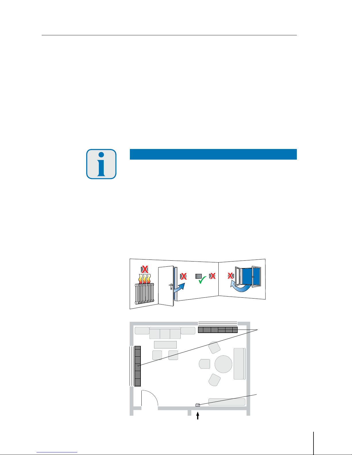
General instructions about the installation site for emcotherm individual room3.1
temperature control components
Install the room thermostat together with the speed controller→
preferably on an inside wall and across from the heating source in
the room.
Install approx. . m above the floor→
Select an installation site that is not close to open doors, windows→
or outside walls
ATTENTION !
ATTENTION !
Attention! Convective air should be able to reach the controller with no
obstruction, meaning to avoid installing the controller behind a curtain
or between shelving or other similar barriers.
Do not expose the controller to direct sunlight and do not install near
lamps, heaters, heating pipes, fireplaces or other electronic devices (TV,
PC etc.), which could emit heat.
When installing a combination of speed controller (DZR) and room
thermostat (RT), we recommend mounting the RT under the DZR
emcotherm
convector
emcotherm
individual room
controller (RT /
emcotime /
emcotronic)
214OI_control_technology_GB_id8506280_0890112.pdf 11 12.01.2009 12:11:42 Uhr
emcotherm control technology
Subject to technical changes without prior notice! June
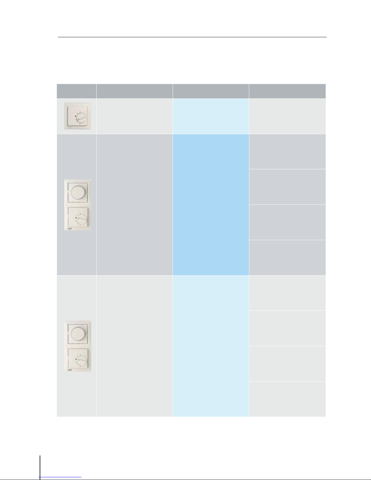
Device Name Recommendation Alternative
emcotherm
for free convection
type KXs, KMs, K 1-K4, K91-K94
Control with
room thermostat RT
Control with programmable
room thermostat
emcotime II
emcotherm
for free and forced convection
type KQs, types KQ1-KQ3
Control with
room thermostat RT
and speed controller DZR
Control with programmable
room thermostat
emcotime II
and speed controller DZR
Control with
room thermostat RT and
fixed speed module FDM
Control with
elektronic climate controller
emcotronic II
Control via
building automation control
(external actuation via
- Volt signal
emcotherm
for free and forced convection
types KQK2, KQKL
(-pipe heat exchanger)
Control with
room thermostat RT
and speed controller DZR
Control with programmable
room thermostat
emcotime II
and speed controller DZR
Control with
elektronic climate controller
emcotronic II
Control with
room thermostat RT and
fixed speed module FDM
Control via
building automation control
(external actuation via
- Volt signal
Recommended use for emcotherm control technology3.2
214OI_control_technology_GB_id8506280_0890112.pdf 12 12.01.2009 12:11:42 Uhr

emcotherm control technology
Subject to technical changes without prior notice! June
Device Name Recommendation Alternative
emcotherm
for free and forced convection
types KQK4, KQKL
(-pipe heat exchanger)
Control with
elektronic climate controller
emcotronic II
Control via
building automation control
(external actuation via
- Volt signal
emcotherm
for free and forced convection
with fresh air connection
type KIQ
Control with
room thermostat RT
Control with programmable
room thermostat
emcotime II
emcotherm
perimeter convectors
for free and forced convection
type BKQ
(-pipe heat exchanger)
Control with
room thermostat RT
and speed controller DZR
Control with programmable
room thermostat
emcotime II
and speed controller DZR
Control with
elektronic climate controller
emcotronic II
Control with
room thermostat RT and
fixed speed module FDM
Control via
building automation control
(external actuation via
- Volt signal
emcotherm
for free and forced convection
type BKQ
(-pipe heat exchanger)
Control with
elektronic climate controller
emcotronic II
Control via
building automation control
(external actuation via
- Volt signal
emcotherm
Circulated air cooling convectors
type EKO
Internal control
214OI_control_technology_GB_id8506280_0890112.pdf 13 12.01.2009 12:11:42 Uhr

emcotherm control technology
Subject to technical changes without prior notice! June
Room thermostat emco RT3.3
The room temperature controller emco RT ( V) with change-over
contact is suitable for heating and cooling in connection with all
emcotherm concector systems.
The controller works with thermal return and a switch temperature
difference of .°K. It has an adjusting knob with temperature range
limit.
Setting emco RT3.3.1
Temperature ranges are set in levels using the adjusting knob (see fig.
at the left). The indicators on the adjusting knob are allocated to the
following temperature ranges.
Scale for setting the temperature range with indicators:
= approx. °C = approx. °C
= approx. °C = approx. ° C
= approx. ° C = approx. °C
3.3.2 General technical data emco RT
Order ID emco RT
Temperature set-point range ... °C
Switch temperature difference approx. . K
Contact (relay) changer, not potential-free
Nominal voltage AC V
Nominal current (cos J= .) heating () A
Nominal current (cos J= .) cooling () A
Switching capacity heating . kW
Switching capacity cooling . kW
Radio shielding level as per VDE / EN
Control mode -point
Temperature sensor bimetallic contact
Casing and frame colour polar white
Night set-back –
214OI_control_technology_GB_id8506280_0890112.pdf 14 12.01.2009 12:11:43 Uhr

emcotherm control technology
Subject to technical changes without prior notice! June
Installing emco RT3.3.3
Installation should be made in a standard flush socket; combination
with a dual frame is possible.
ATTENTION !
ATTENTION !
If emco RT is installed together with speed controller emco DZR in a
dual frame, emco RT should be installed below the speed controller.
Electrical connection emco RT3.3.4
ATTENTION !
ATTENTION !
Connect all wiring as described in the corresponding schematic
diagram.
Ensure that the neutral wire N is connected to terminal N. If this
is not done, the controller will not work properly, resulting in high
temperature fluctuations.
Wire size: to . mmsolid wire:
No grounding wire necessary because the device has protective
insulation.
Schematic diagram:
Speed controller emco DZR (install at TOP)
Room thermostat emco RT (install at BOTTOM)
Short description of the
schematic diagram
L = External wire (phase)
N = Neutral wire (formerly Mp)
= Load terminal heating
= Load terminal cooling
RF = Resistance for thermal
return
214OI_control_technology_GB_id8506280_0890112.pdf 15 12.01.2009 12:11:43 Uhr
emcotherm control technology
Subject to technical changes without prior notice! June
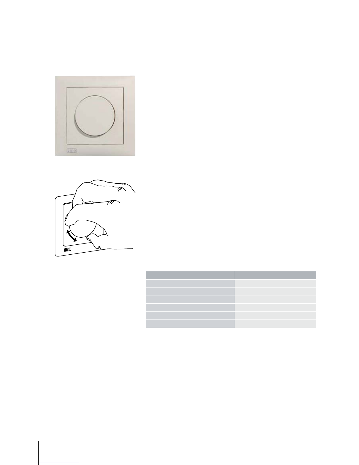
Speed controller emco DZR3.4
The electronic potentiometer emco DZR is for continuous speed control
of emcotherm convectors with an output signal of - V.
DZR is used in combination with emco RT or emcotime II.
With a closed contact in the emco RT/emcotime II, use DZR to regulate
the fan speed/thermal output of emco convectors.
Setting DZR3.4.1
Set the fan speed by turning the adjustment knob.
clockwise = increase speed→
counter clockwise = reduce speed→
General technical data emco DZR3.4.2
Order ID emco DZR
Contact (relay) potentiometer
Control voltage . V ... V
Control current max. mA
Micro-fuse F H
Max. clampable wire size x . mm
Casing and frame colour polar white
214OI_control_technology_GB_id8506280_0890112.pdf 16 12.01.2009 12:11:43 Uhr
emcotherm control technology
Subject to technical changes without prior notice! June
Installation3.4.3
Installation should be made in a standard flush socket; combination
with a dual frame is possible.
ATTENTION !
ATTENTION !
If emco DZR is installed together with room thermostats emco RT or
emcotime II in a dual frame, emco DZR should always be installed
above the room thermostat (see fig. below
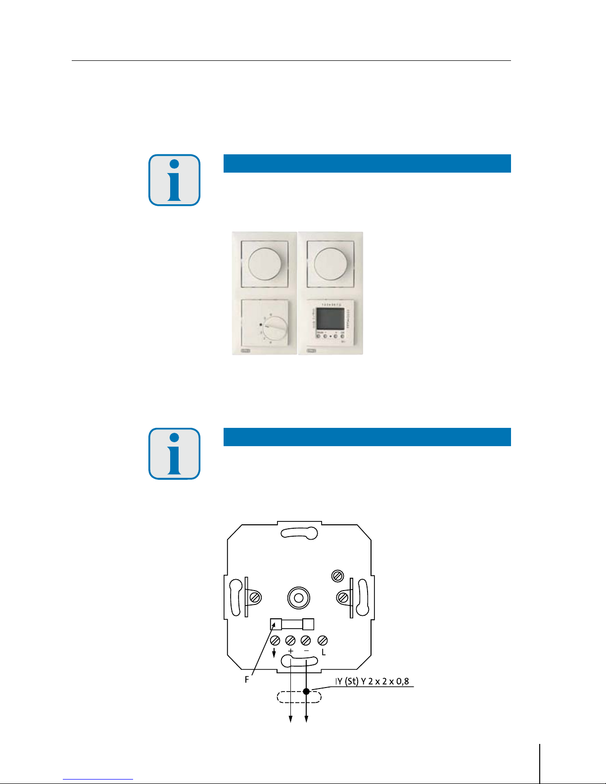
Electrical connection3.4.4
Connect the electronic potentiometer according to the schematic
diagram.
In integrated micro-fuse protects the - V control circuit in the event
of incorrect wiring.
ATTENTION !
ATTENTION !
If there is a malfunction, first check the micro-fuse “F“ (see schematic
diagram).
Use only original fuses.
Schematic diagram:
Speed controller emco DZR
(always install at TOP)
Room thermostat emco RT or
emcotime II
(always install at BOTTOM)
214OI_control_technology_GB_id8506280_0890112.pdf 17 12.01.2009 12:11:43 Uhr

1
2
3
4
5
emcotherm control technology
Subject to technical changes without prior notice! June
Electronic climate controller emcotronic II3.5
Electronic room thermostat for fixed set-point control (constant PI-
control) for use in emcotherm convectors with -pipe and -pipe
technology (for heating and cooling).
Functional components emcotronic II3.5.1
Displays for operation mode and
operating status:
1. Occupancy indicator
(green LED)
LED ON = Comfort mode
(room occupied)
LED OFF = Economy mode
(room not occupied)
2. Heating (red LED)
LED ON = Heating mode ON
LED OFF = Heating mode OFF
3. Cooling (yellow LED)
LED ON = Cooling mode ON
LED OFF = Cooling mode OFF
Operation components:
4. Occupancy button
a) to switch between
“room occupied“ and
“room not occupied“
b) to activate programme
mode
5. Adjusting knob
to set the room temperature
(set-point temperature)
214OI_control_technology_GB_id8506280_0890112.pdf 18 12.01.2009 12:11:43 Uhr

emcotherm control technology
Subject to technical changes without prior notice! June
Short description emcotronic II3.5.2
The room thermostat displays the current operation mode:
Heating mode:→red LED illuminated
Cooling mode:→yellow LED illuminated
When the red and yellow LED are not illuminated, set-point and→
actual temperature correspond. Neither heating nor cooling is
taking place, the valves are not being triggered.
Use the occupancy button to switch between ‘room occupied’ and
‘room unoccupied’
‘Room occupied’: (→green LED illuminated) means comfort mode,
controlling according to the set value.
‘Room unoccupied’: (green LED off) means economy mode.→
When heating, the mode will operate at K less and when cooling
at K more.
The following operation states are possible:
Occupancy Heating Cooling Set-Point Temperature
Room occupied
(comfort mode)
Heating
Room occupied
(green + red LED on)
Cooling
Room occupied
(green + yellow LED on)
Set point temperature
= actual temperature
Room occupied
(only green LED on)
Room unoccupied
(economy mode)
K decreased
heating
room unoccupied
(only red LED on)
K increased
cooling
room unoccupied
(only yellow LED on)
Set-point-temperature
is equal to
actual temperature
room unoccupied
(no LED on)
214OI_control_technology_GB_id8506280_0890112.pdf 19 12.01.2009 12:11:43 Uhr

emcotherm control technology
Subject to technical changes without prior notice! June
Setting the set-point temperature with emcotronic II3.5.3
The desired room temperature (set point temperature) can be set using
the adjusting knob.
The maximum and minimum adjustable set point temperatures
(possible setting range) can be limited mechanically through the use of
a limiting pin.
Do this to limit the setting range: mechanical maximum value limit
( + stop)
. Turn the adjusting knob clockwise to the maximum limit (+) .
. Insert the limiting pin ca. mm and turn back the knob to the
desired maximum temperature, fixing this temperature via limiting
pin.
Mechanical minimum value limit ( - stop
. Turn the adjusting knob counter clockwise to the minimum limit (-).
. Insert the limiting pin ca. mm turn back the knob to the desired
minimum temperature, fixing this temperature via limiting pin.
214OI_control_technology_GB_id8506280_0890112.pdf 20 12.01.2009 12:11:44 Uhr
This manual suits for next models
14
Table of contents
Popular Control Unit manuals by other brands

Sera
Sera 620.10 operating instructions

IFM Electronic
IFM Electronic PDM360 NG-12 Programming manual

Pentair
Pentair FLECK 2750 Downflow Service manual

ELECTRONIC ASSEMBLY
ELECTRONIC ASSEMBLY DISPLAY VISIONS EA eDIP Series manual

Penn
Penn V46 Series Repair Parts and Service Instructions

Avnera
Avnera AV6200 user manual

Cerlic
Cerlic MultiFix manual

Hach
Hach RTC101 Basic user manual

Siemens
Siemens TL-30U installation instructions

gs yuasa
gs yuasa LIM50EN-12S2-F2 instruction manual

Victaulic
Victaulic KOIL-KIT 799 Series Installation and maintenance instructions

Grundfos
Grundfos CIM 2 Series Installation and operating instructions


