Emerald Marine Alert2 User manual

MAN-OVERBOARD ALARM SYSTEM
OWNER’S MANUAL
INTRODUCTION
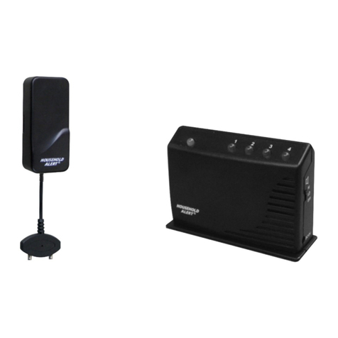
The ALERT2 Man-Overboard Alarm System™ consists of the ALERT2 Receiver and
one or more ALERT2 Transmitters. Upon activation of the Transmitter by either totally
immersing the ALERT2 Transmitter in water (salt or fresh), or by manual activation, a
coded radio signal will be transmitted to the ALERT2 Receiver, causing the internal
alarm to sound, and the relay contacts to function, activating any auxiliary devices
connected. Both the Transmitter and Receiver will latch to the MOB condition once
activated, so that the Transmitter will continue to transmit even if removed from wa-
ter until turned off, and the Receiver will continue to sound its alarm until turned off.
The range of the System is one nautical mile maximum and depends on the antenna
installation, sea conditions, and position of the man-overboard.
The ALERT2 Transmitter and the ALERT2 Receiver comply with the U.S. Federal
Communications Commission Rules (Part 15), and with Industry Canada Rules, and do
not require a license. Changes or modifications to the ALERT2 Transmitter or ALERT2
Receiver not expressly approved by Emerald Marine Products could void the user’s
authority to operate these devices, and will void the warranty.
SPECIFICATIONS
ALERT2 Man-Overboard Transmitter™:
Weight: 4 ounces with batteries
Dimensions: 5.5” x 1.5” x .75”
Case: High impact polycarbonate
Watertight integrity: 200 feet water depth maximum
Power supply: Two 3.6 volt AA size lithium batteries (NOT 1.5 volt AA)
Controls: Off/Armed
Attachment: Nylon pouch
Approvals: FCC & Industry Canada. No license required
Frequency: 418MHz
Range: One nautical mile
Antenna: Internal
Transmitting life: Three hours minimum at -4F (-20C)
Operating temperature: -4F to 130F (-20C to 55C)
Storage temperature: -40F to 158F (-40C to 70C)
ALERT2 Man-Overboard Receiver™:
Power supply: 12 volt, 100 mA external
Dimensions: 4” W x 2” H x 5” D
Weight: 12 ounces
Mounting: Yoke bracket or flush mount kit (included)
Antenna: 18” whip with 25’ coaxial cable
Internal alarm: 95dB, front panel mounted GPS/Chartplotter/ Remote
alarm/Engine shutdown: Relay contacts normally open,
and normally closed, 1A maximum
Operating temperature: -4F to 130F (-20C to 55C)
Storage temperature: -40F to 158F (-40C to 70C)
ALERT2 Man-Overboard Portable Direction Finder™ (not pictured in manual):
Dimensions: 20” x 14” x 4”
Weight: 2 pounds
Controls: OFF/ON/Volume
Power supply: one 3.6 volt AA size lithium battery
Indicator: Spray tight loud speaker
Warranty on all ALERT2 products: 3 year parts and labor
Product is Made in the U.S.A.
6206 1ST AVENUE NW
SEATTLE, WASHINGTON | 98107
P. 206.965.8207
TOLL FREE 800.426.4201
WWW.ALERT2.COM
6206 1ST AVENUE NW
SEATTLE, WASHINGTON | 98107
P. 206.965.8207
TOLL FREE 800.426.4201
WWW.ALERT2.COM

INSTALLATION
Antenna:
The antenna cable is 25 feet of RG8X coaxial cable with a UHF plug at the antenna end, and a
BNC plug at the receiver end. The antenna coax can be extended using a UHF-UHF connec-
tor. Mount the antenna on a cabin top or stern rail at least three feet from large metal objects.
Do not install the antenna on the masthead. Minimize blockage from vessel structures, and
maintain an approximately clear line-of-sight to the stern.
Receiver Mounting:
The Receiver is not watertight. Mount the Receiver in a dry location in the wheelhouse or
navigation station. The yoke bracket may be used for overhead or countertop mounting, or the
Receiver may be flush-mounted. Remove the two rear setscrews and the two side panel jacks
by sliding rearward. To yoke mount use bracket and thumbscrews provided. To flush mount
cut hole 3 5/8 in wide x 1 3/4 in high (max thickness: 3/8 in). Install Receiver through front,
securing from rear with side panel jacks and rear setscrews.
Receiver Rear Panel Connections:
ANT (antenna): Connect the plug on the end of the antenna cable to the ANT jack on the rear
of the Receiver.
NO (normally open): This terminal of the internal relay is normally open (not connected) to the
C (common) terminal, and closes to the C (common) terminal when the Receiver detects an
ALERT2 Transmitter signal.
C (common): This terminal of the internal relay is normally connected to the NC terminal, and
disconnects from the NC terminal and connects to the NO terminal, when the Receiver detects
an Alert Transmitter signal.
NC (normally closed): This terminal of the internal relay is normally closed (connected) to
the C (common) terminal, and opens (disconnects) from the C (common) terminal when the
Receiver detects an ALERT2 Transmitter signal.
GPS/Chartplotter: Connect NO and C to a compatible GPS or Chartplotter that has
connections for external waypoint mark or external MOB triggering. Call Emerald Marine
Products for a list of compatible GPS’s and Chartplotters.
Ship’s General Alarm: Connect NO and C to dry contact inputs of the Ship’s General Alarm.
External Alarm: The internal relay contacts are rated 1 amp maximum, so an external
relay will be necessary if your External Alarm current exceeds 1 amp. Connect the posi-
tive wire of your External Alarm to your external relay at a normally open terminal. Connect
the +12 volt terminal on the receiver to your external relay to the common terminal on the
same set of relay contacts. Connect the negative wire of your External Alarm to the GND
terminal on the receiver. Connect one relay coil terminal on your external relay to receiver
terminal NO, connect your other external relay coil terminal to receiver terminal GND, and
connect a short jumper from receiver terminal C to receiver terminal +12. Call Emerald Marine
Products at 800-426-4201 for wiring diagrams and help.
Engine Shutdown: The internal relay contacts are rated 1 amp maximum, so an external relay
will be necessary. Connect one relay coil terminal on your external relay to receiver terminal
NO, connect your other external relay coil terminal to receiver terminal GND, and connect a
short jumper from receiver terminal C to receiver terminal +12. Connect your external relay
contacts in parallel with engine circuits that apply 12 volt power to kill the engine, or connect
your external relay in series with engine circuits that remove 12 volt power to kill the engine.
Call Emerald Marine Products at 800-426-4201 for wiring diagrams and help.
GND (ground): Connect to the vessel’s negative DC electrical ground.
+12V: Connect to a source of positive 12 volts DC. The Receiver draws 100 milliamps.
Fuse Replacement: Remove front panel screws and front panel with bezel trim. Remove
rear panel screws. Slide rear panel to rear, exposing fuses on circuit board. Fuse F1 (1 amp)
protects the receiver. Fuse F2 (1 amp) protects the internal relay.
Transmitter:
Insure the Transmitter is mounted high on the chest, as radio waves do not travel underwater.
The ALERT2 Transmitter can be worn in 2 ways:
1. With the plastic wire ties (provided) through the slots at the top and bottom of the pouch,
secured to a work vest, high on the chest. 2. In a chest or arm pocket, located high on the
chest.
Digital Code:
All ALERT2 Transmitters and Receivers use an 8-bit digital code. The code is factory set
with one code for each ALERT2 customer, to prevent interference between customers. If you
choose to change the code, please call us at 800-426-4201.
OPERATION
Receiver:
Turn front panel power switch to the ON position. Observe the green POWER ON light.
If the Receiver detects a Transmitter, the internal alarm will sound, the red MAN-OVERBOARD
light will illuminate, and the internal relay contacts will function, activating any auxiliary devices
connected. The Receiver will latch in the MOB mode once activated, so that the Receiver will
continue to sound its alarm until turned off.
Transmitter:
Arming: Do not forget to ARM the Transmitter before use, as they are shipped unarmed.
To arm: Turn the cap clockwise fully, as the label indicates.
Test the system as often
as desired. (Notify the person nearest the receiver first.) The Transmitter will continue to
transmit even if removed from water until turned off by unscrewing the cap 2 full turns, per the
instructions on the label.
Water Activation:
Activate the Transmitter by totally immersing the Transmitter in water (salt or fresh).
Manual Activation:
Activate the Transmitter by wetting the index finger and thumb, and touching the index finger
to the bare water activation electrode, and touching the thumb to the black rubber shrouded
water activation electrode.
MAINTENANCE
Test each Transmitter separately, using the Receiver, by activating the Transmitter in a bucket
of water. Check that when activated and removed from the bucket of water, the Transmitter
continues to transmit, as indicated by the green flashing LED blinking on the Transmitter. The
Receiver alarm sounds. The red Man-Overboard light will illuminate, and the internal relay con-
tacts will function, activating any auxiliary devices connected.
Battery Replacement:
1. Replace batteries after emergency use, or after expiration of 10 year shelf life (see date
on battery).
2. Requires two 3.6volt AA-size lithium batteries. Call us at 800-426-4201 to order. AA100
3. Unscrew cap. Pull out circuit board. Drop out old batteries.
4. Install new batteries (follow polarity arrows on inside label).
5. Reinstall circuit board (follow alignment instructions on inside label) (align LED on circuit
board with the word “LED” on label).
6. Reinstall cap and screw down fully to rearm the transmitter.
Other Emerald Marine Security System manuals


