manuals.online logo
Brands
  1. Home
  2. •
  3. Brands
  4. •
  5. E2S
  6. •
  7. Security System
  8. •
  9. E2S HA121 User manual

E2S HA121 User manual

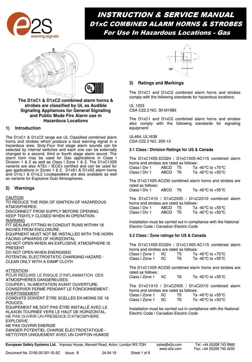
This manual suits for next models

3

Other E2S Security System manuals

E2S GNExCP6B-PT User manual

E2S

E2S GNExCP6B-PT User manual

E2S GNExS1 User manual

E2S

E2S GNExS1 User manual

E2S Appello A121APPX User manual

E2S

E2S Appello A121APPX User manual

E2S D1 B2LD2 Series User manual

E2S

E2S D1 B2LD2 Series User manual

E2S D2xC1 Troubleshooting guide

E2S

E2S D2xC1 Troubleshooting guide

E2S MBLD2 Series User manual

E2S

E2S MBLD2 Series User manual

E2S SONFL1H-HO Series User manual

E2S

E2S SONFL1H-HO Series User manual

E2S BExCTS110-05D-P User manual

E2S

E2S BExCTS110-05D-P User manual

E2S STExS2 User manual

E2S

E2S STExS2 User manual

E2S GNExCP6B-PB User manual

E2S

E2S GNExCP6B-PB User manual

E2S D1xB2X05 Series User manual

E2S

E2S D1xB2X05 Series User manual

E2S BExBG21D-P User manual

E2S

E2S BExBG21D-P User manual

E2S GNExB2LD2 User manual

E2S

E2S GNExB2LD2 User manual

E2S BExBG15D-P-SIL User manual

E2S

E2S BExBG15D-P-SIL User manual

E2S D1*CP1-PS Series User manual

E2S

E2S D1*CP1-PS Series User manual

E2S APPELLO A121AX User manual

E2S

E2S APPELLO A121AX User manual

E2S BexCS11005D24DC-RD User manual

E2S

E2S BexCS11005D24DC-RD User manual

E2S D2xC2LD3 User manual

E2S

E2S D2xC2LD3 User manual

E2S D1xS1FDC024-S User manual

E2S

E2S D1xS1FDC024-S User manual

E2S BExCP3C-PB User manual

E2S

E2S BExCP3C-PB User manual

E2S D2 C2X05DC024 Series User manual

E2S

E2S D2 C2X05DC024 Series User manual

E2S BExCBG05-05D User manual

E2S

E2S BExCBG05-05D User manual

E2S BExCBL2-L2D-P User manual

E2S

E2S BExCBL2-L2D-P User manual

E2S GNExCP7-BG-S User manual

E2S

E2S GNExCP7-BG-S User manual

Popular Security System manuals by other brands

Polon-Alfa 4000 Installation and maintenance manual

Polon-Alfa

Polon-Alfa 4000 Installation and maintenance manual

Nexcom NViS 14162 Series user manual

Nexcom

Nexcom NViS 14162 Series user manual

Eminent EM8670 Quick install

Eminent

Eminent EM8670 Quick install

urmet domus alpha 1060 INSTALLATION AND USE BOOKLET

urmet domus

urmet domus alpha 1060 INSTALLATION AND USE BOOKLET

SmartPool YardGuard YG03 manual

SmartPool

SmartPool YardGuard YG03 manual

DSC PC5964 Mounting instructions

DSC

DSC PC5964 Mounting instructions

Secure USAB-1 operating instructions

Secure

Secure USAB-1 operating instructions

B&B 480 SERIES Operation & maintenance manual

B&B

B&B 480 SERIES Operation & maintenance manual

ADEMCO VISTA-20P Series Installation and setup guide

ADEMCO

ADEMCO VISTA-20P Series Installation and setup guide

Inner Range Concept 2000 user manual

Inner Range

Inner Range Concept 2000 user manual

Johnson Controls PENN Connected PC10 Install and Commissioning Guide

Johnson Controls

Johnson Controls PENN Connected PC10 Install and Commissioning Guide

Aeotec Siren Gen5 quick start guide

Aeotec

Aeotec Siren Gen5 quick start guide

Swann SW-P-MC2 Specifications

Swann

Swann SW-P-MC2 Specifications

Ecolink Siren+Chime user manual

Ecolink

Ecolink Siren+Chime user manual

EDM Solution 6+6 Wireless-AE installation manual

EDM

EDM Solution 6+6 Wireless-AE installation manual

Siren LED GSM operating manual

Siren

Siren LED GSM operating manual

Detection Systems 7090i Installation and programming manual

Detection Systems

Detection Systems 7090i Installation and programming manual

FRIEDLAND MA10 Installation and operating instructions

FRIEDLAND

FRIEDLAND MA10 Installation and operating instructions

manuals.online logo
manuals.online logoBrands
  • About & Mission
  • Contact us
  • Privacy Policy
  • Terms and Conditions

Copyright 2025 Manuals.Online. All Rights Reserved.

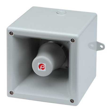
HA121 -HAL121 -HAL121L -HAL121B
Hootronic: Alarmsounderand combined audiovisualsignalling device
Tel:0044(0)2087438880 mail : sales@e2s.com Fax :0044(0)2087404200 web: www.e2s.com
INSTALLATION INSTRUCTIONS
Voltage range and current
consumption forthe HAL121
HootronicAlarmwith5JXenon:
Voltage range and current
consumption forthe HA121
HootronicAlarmHorn:
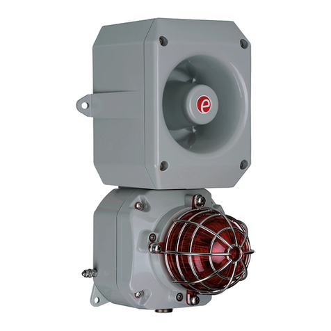
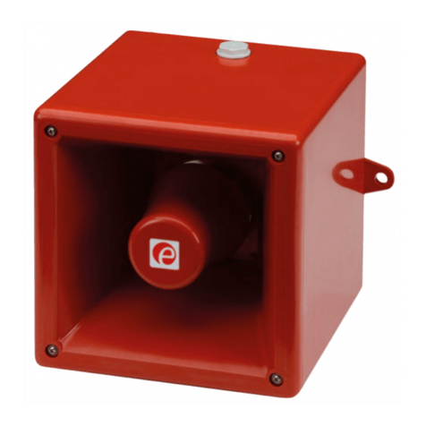
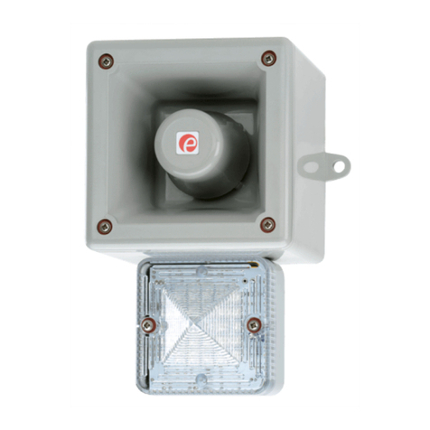
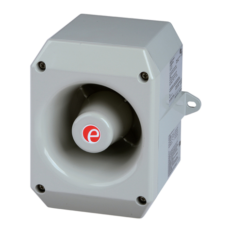
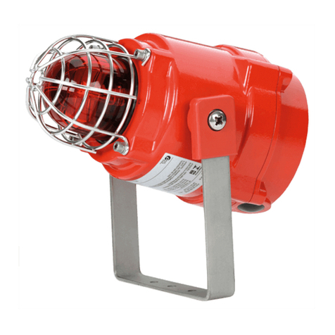
HA121: HootronicAlarmHorn HAL121: HootronicAlarmHorn
combined witheitherXenon,
filament bulb orL.E.Dbeacon.
Applicationsandusersthathavetraditionallydemanded conventional
electromechanicalhooters,sirens,buzzersand bellscannowchoosethe
nextgenerationalternative. The technologyused inthe Hootronicrange
featuresthe latest inamplifierand digitaltoanalogue conversion
technology.
The E2SHootronicseriesof productsfaithfullyreproducethe sounds
madebytraditionalelectro-mechanicalsignalling devicesbutinamodern,
reliableand cost effectiveway.Withoutput levelsofup to121dB(A)at1
metretheHootronicalsosurpassestheperformanceand effectivenessof
itstraditionalcounterpart. Unlikethetraditionalelectro-mechanicaldevices
theHootronicrange iscontinuouslyrated, requireszeromaintenanceand
signalqualityand performancewill not degrade withage.
Thelightweight, durablehousingsaremanufacturedfromimpact and fire
resistant UL94V0&5VA ABS. The unitcan alsobe supplied ascombined
unit(theHAL121version)witheithera5JouleXenon, L.E.Dorfilament
bulbbeacon inachoiceofup to7lenscolours.
Voltage range and current
consumption forthe HAL121L
HootronicAlarmwithL.E.Dbeacon:
Voltage range and current
consumption forthe HAL121L
HootronicAlarmwithBulb beacon:
210,00
190,00
190,00
Ø9,00
184,00
191 ,50
1 90 ,0 0
210,00
190,00
Ø9,00
All dimensionsarein millimetres.
2 74, 00
190,00
Specifications:
lNominaloutput:121dB(A)@1m+/-3dB
l3stage alarmoption
lVolumecontrol
l300meffectiverange
lVoltages:24vdc; 115vac;230vac
lHA121: IP55 (uptoIP66 dust protected&watertightwithWRkit)
lHAL121: IP55 (uptoIP56 withWRkit)
lEnclosurematerial:UL94V0&5VA rated FRABS
lColouravailable: Red(RAL3000),Grey(RAL7035)
lOperatingtemperature: -25to+55°C
lStorage temperature:-40to+70°C
lRelativehumidity: 90%at20°C
lWeightHA121: DC: 2.10KgAC: 2.70Kg
HAL121: DC: 2.30KgAC: 2.90Kg
HAL121: Xenon:5Joule@1Hz(5Ws)(60 FPM)
HAL121L: L.E.D:8xL.E.Darray(Steadyorflashing @2Hz).
HAL121B: Bulb: Filament3watt (Steadyorflashing @1.5Hz). >121dB(A)@1m.
Voltage: 24vdc 115vac 230vac
50/60Hz 50/60Hz
Range: +/-25% +/-10% +/-10%
Current: 645mA 270mA 130mA
Voltage: 24vdc 115vac 230vac
50/60Hz 50/60Hz
Range: +/-25% +/-10% +/-10%
Current: 475mA 204mA 102mA
Voltage: 24vdc 115vac 230vac
50/60Hz 50/60Hz
Range: +/-25% +/-10% +/-10%
Current: 500mA 190mA 90mA
Voltage: 24vdc 115vac 230vac
50/60Hz 50/60Hz
Range: +/-25% +/-10% +/-10%
Current: 375mA 160mA 75mA
NOTE:
lIf applicablepleasereviewaccompanying
installation instructionsfordetailsregarding the
xenon, bulborL.E.Dbeacon.
lCablesforconnectingthe soundertothe beacon
aresupplied withtheproduct.
ISN5201-A
ATTENTION
Noliabilityisaccepted foranyconsequenceofthe useofthisdocument. Thetechnicalspecification of thisunitissubjecttochange without noticeduetoourpolicy
ofcontinualproduct development. Alldimensionsareapproximate.Thisunit issoldsubject toourstandardconditionsofsale,acopyof whichisavailableon
•Disconnectfrompowersource topreventelectrical shock beforeinstalling and servicing
•Couperl’alimentation pourempêchertoutchocélectriqueavantd’effectuerdes travauxd’installationet
d’entretien.
•VorderInstallationund Wartungvon derSpannungsquelleabnehmen,umelektrischeSchlägezuvermeiden.
•Primadell’installazioneedellamanutenzionespegnerel’alimentazioneelettricaperevitarescosse
elettriche.
•Desconectelaalimentaciónparaevitardescargaseléctricasantes delainstalación ymantenimiento
•Antes deinstalaroudefazeramanutençãodesliguesempredaalimentaçãoeléctricaparaevitarchoques
eléctricos.
•Strømmenskal afbrydes vedinstallering og eftersynforatundgåelektrisk stød.
•Loskoppelenvandeelektrischevoedingomelektrischeschokvóórinstallatieenonderhoudtevoorkomen.
•Førmontering ellervedlikehold,måspenningenkoples fraforåunngåstrømstøt.
•Brytströmmeninnaninstallationochunderhåll förattförhindraelektriska stötarstötar.
Wiring configuration for24vdcunits. Wiring configuration for115, 230vacunits.
Fig. 1
Stage1 Alarm Stage2 Stage3
tone Description (S2) (S3) Header
3
Tone 1
IndustrialHooter
Tone 3
Tone 5
2
1
3
Tone 2
High Frequency MechanicalSiren
Tone 1
Tone 5
2
1
3
Tone 3
MediumFrequency MechanicalSiren
Tone 1
Tone 5
2
1
3
Tone 4
ElectroMechanicalBuzzer
Tone 1
Tone 5
2
1
3
Tone 5
MechanicalBell
Tone 1
Tone 2
2
1
Fig. 2
Mounting and cabling instructions:
The unit can be mounted witheitherthe external lugsorbyfixing
through the backof the housing. Forinternal fixing the HA121 has
BESAcompatible fixing positionsmarked.
THeHA121 isshipped withone M20 clearancecable entryhole
populated withan IP55 stopping plug. Forinstallationsrequiring
the cable entrytobe through the rearof the unit aM20 clearance
‘knockout’islocated in the centreof the backwall of the housing.
The terminalsin the HA121 and HAL121 productswill accept from
0.5mm²to4.0mm²stranded orsingle corecables.
DC units:
DC powersupplyconnectionsshould be made tothe +and -
terminals.
Toremotelyswitchthe second and thirdstage soundscable into
the terminalsmarked ‘S2’and ‘S3’respectively. Toactivatethe
second and thirdstage soundsswitch‘S2’or‘S3’tothe negative
supplywhilst the unit ispowered (see Fig.1). Stage 2overides
stage 1and stage 3overidesstage 2.
The Hootronicsounderhasthe facilitytoreplicatethe ‘tail off’
traditionallyassociated withthesetone when generated by
electro-mechanical devices. The switching isachieved bycabling
intothe terminal marked STOP.The usercan remotelyactivate
and de-activatethe sounderbyswitching the connection between
the STOPwireand the negativesupplyline whilst the unit is
powered. Toachievethe ‘tail off’sound at switchoff the unit must
remain powered.
ACunits:
ACpowersupplyconnectionsshould be made tothe L, Nand E
terminals.
Toremotelyswitchthe second and thirdstage soundscable into
the terminalsmarked ‘C/-’, ‘S2’and ‘S3’respectively. Toactivate
the second and thirdstage soundsswitch‘S2’or‘S3’tothe ‘C/-’
cable whilst the unit ispowered (see Fig.1). Stage 2overides
stage 1and stage 3overidesstage 2.
The Hootronicsounderhasthe facilitytoreplicatethe ‘tail off’
traditionallyassociated withthesetone when generated byelectro-
mechanical devices. The switching isachieved bycabling intothe
terminalsmarked STOPand ‘C/-’.The usercan remotelyactivate
and de-activatethe sounderbyswitching the connection between
STOPand the ‘C/-’cableswhilst the unit ispowered. Toachieve
the ‘tail off’sound at switchoff the unit must remain powered.
ToneSelection:
TheHootronicHA121, HAL121,HAL121LandHAL121Bhave5userselectable‘traditional’ sounds:
Tone1: Industrial Hooter
Tone2: HighFrequency MechanicalSiren
Tone3: MediumFrequency MechanicalSiren
Tone4: ElectroMechanicalBuzzer
Tone5: MechanicalBell
Eachofthesesoundshastwoadditional, remotelyselectable, alarmstagesasshownin thetable below
(seeFig2.).The firststagetoneisselected bymeansof the pin headersmarked 1,2,3on the PCBA.
Usethe supplied jumperconnectorstoselect the required tone byfollowing the diagrams in the table below
See ‘Mounting and cabling instructions’fordetailsof howtoactivatethe second and thirdstages.