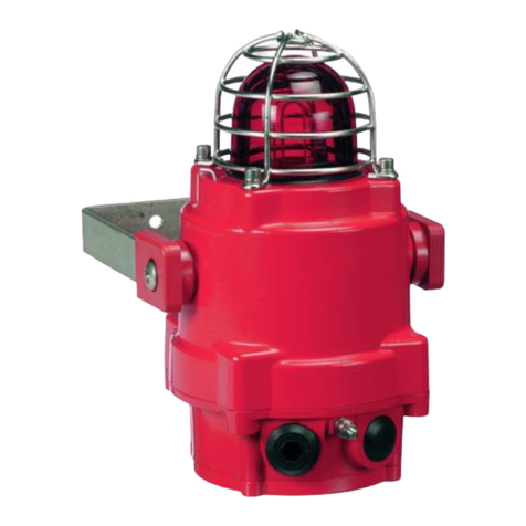
Pfannenberg BExBG05D-P User manual

BExBG05D-P
Pfannenberg GmbH · Werner Witt-Straße 1 · D-21035 Hamburg · Tel.: 040/7 34 12-0 · www.pfannenberg.com
03/2022 Seite 1 / 5 30017-015-1e
BEDIENUNGSANLEITUNG (ATEX)
BExBG05D-P XENON LEUCHTE
Zur Verwendung in Umgebungen mit entzündlichen Gasen
und Stäuben
1) Warnungen
•NICHT ÖFFNEN WENN EXPLOSIVE AT-
MOSPHÄRE VORHANDEN IST
•GERÄT NICHT ÖFFNEN WENN UNTER
SPANNUNG
•GEFAHR ELKTROSTATISCHER ENTLA-
DUNG. NUR MIT FEUCHTEM TUCH
REINIGEN
•DECKELSCHRAUBEN KLASSE A4-80
•NUR HITZEBESTÄNDIGE KABEL UND
KABELVERSCHRAUBUNGEN (ZUGE-
LASSEN BIS 110°C) BEI UMGEBUNGS-
TEMPERATUREN ÜBER 40°C VER-
WENDEN
2) Einstufung und Kennzeichnung
Alle Geräte sind mit einem Typenschild mit folgenden wichti-
gen Informationen gekennzeichnet:
Type.: BExBG05D-P
Nennspannung: DC -Geräte 12V oder 24V oder 48V
AC -Geräte 115V oder 230V
Kennzeichnung:
II 2G Ex db IIC T5 Gb Ta. -50°C bis +40°C
II 2G Ex db IIC T4 Gb Ta. -50°C bis +70°C
II 2D Ex tb IIIC T93°C Db Ta. -50°C bis +40°C
II 2D Ex tb IIIC T108°C Db Ta. -50°C bis +55°C
II 2D Ex tb IIIC T123°C Db Ta. -50°C bis +70°C
Zertifikat-Nr.KEMA 01ATEX2030 X
Die Geräte können in den folgenden Umgebungen und un-
ter folgenden Bedingungen eingesetzt werden:
Klassifizierung des Gasbereichs:
Zone 1 Auftreten von explosionsfähigem Gas/Luft-Ge-
misch im Normalbetrieb möglich.
Zone 2
Auftreten von explosionsfähigem Gas/Luft-Ge-
misch im Normalbetrieb unwahrscheinlich,
falls doch auftretend, dann nur kurzzeitig.
Gasgruppen:
Gruppe IIA
Propan
Gruppe IIB
Äthylen
Gruppe IIC
Wasserstoff und Acetylen
Temperaturklassifizierung:
T1
450ºC
T2
300ºC
T3
200ºC
T4
135ºC
T5
100ºC (bis +40ºC Umgebungstemperatur)
Klassifizierung des Staubbereichs:
Zone 21 Auftreten von explosionsfähigem Staub/Luft-
Gemisch im Normalbetrieb möglich.
Zone 22
Auftreten von explosionsfähigem Staub/Luft-
Gemisch im Normalbetrieb unwahrscheinlich,
falls doch auftretend, dann nur kurzzeitig.
Staubgruppen
Gruppe IIIA
Brennbare Stäube
Gruppe IIIB
Nichtleitende Stäube
Gruppe IIIC
Leitende Stäube
Maximale Oberflächentemperatur bei Staub-Anwendungen:
93ºC bei +40ºC Umgebungstemperatur
108ºC bei +55ºC Umgebungstemperatur
122ºC bei +70ºC Umgebungstemperatur
IP-Schutzart: IP66/67 gemäß EN/IEC60529 und IP6X
gemäß EN/IEC60079-0, EN/IEC60079-31
Gerätekategorie:2G / 2D
Geräteschutzniveau:Gb / Db
Umgebungstemperaturbereich:
-50°C bis +70°C Gasgruppen IIA, IIB und IIC
-50°C bis +70°C Staubgruppen IIIA, IIIB und IIIC
0344
Epsilon Kappa
Gerätegruppe und
Kategorie:
CE-Kennzeichnung
Nr. Zertifizierungs-
stelle
II 2G
II 2D

Pfannenberg GmbH · Werner Witt-Straße 1 · D-21035 Hamburg · Tel.: 040/7 34 12-0 · www.pfannenberg.com
03/2022 Seite 2 / 5 30017-015-1e
3) Anzuwendende Normen
Die Leuchte verfügt über ein CE-Typ-Prüfzertifikat entspre-
chend den Anforderungen folgender Normen:
EN IEC 60079-0:2018 / IEC60079-0:2017 (Ausgabe 7): Ex-
plosionsgefährdete Bereiche - Betriebsmittel. Allgemeine
Anforderungen
EN60079-1:2014 / IEC60079-1:2014 (Ausgabe 7): Explosi-
onsgefährdete Bereiche - Geräteschutz durch druckfeste
Kapselung „d“
EN 60079-31:2014 / IEC60079-31:2013 (Ausgabe 2):
Explosionsgefährdete Bereiche - Geräte-Staubexplosions-
schutz durch Gehäuse „t“
4) Installationsanforderungen
Die Leuchte darf nur von qualifiziertem Fachpersonal in
Übereinstimmung mit folgenden aktuellen Normen installiert
werden.
EN60079-14 / IEC60079-14: Explosionsgefährdete Berei-
che - Projektierung, Auswahl und Errichtung elektrischer
Anlagen
EN60079-10-1 / IEC60079-10-1: Explosionsgefährdete Be-
reiche - Einteilung der Bereiche. Gasexplosionsgefährdete
Bereiche
EN60079-10-2 / IEC60079-10-1: Explosionsgefährdete Be-
reiche - Einteilung der Bereiche. Staubexplosionsgefährdete
Bereiche
Die Installation der Leuchte hat unter Einhaltung der zutref-
fenden örtlichen Vorschriften durch einen entsprechend aus-
gebildeten und fachkundigen Elektrotechniker zu erfolgen.
5) Besondere Nutzungsbedingungen
Die Reparatur des flammendurchschlagsicheren Spalts ist
nicht erlaubt.
Das Gehäuse ist nichtleitend und kann unter gewissen ext-
remen Bedingungen (z.B. Hochdruckdampf) eine zündfähige
Entladung auslösen. Der Anwender muss sicherstellen, dass
das Betriebsmittel nicht in einem Bereich installiert wird, in
dem es äußeren Bedingungen ausgesetzt ist, die zu einer
elektrostatischen Aufladung auf nichtleitenden Oberflächen
führen können.
Das Gerät darf außerdem nur mit einem feuchten Lappen ge-
reinigt werden.
6) Standort und Montage
Der Standort der Leuchte sollte so ausgewählt werden, dass
die Warnsignale gut sichtbar sind. Das Gerät darf nur an Vor-
richtungen befestigt werden, die für das Gewicht des Geräts
ausgelegt sind.
Das Gerät ist mit Hilfe des U-förmigen Haltewinkels aus rost-
freiem Stahl an einer geeigneten flachen Oberfläche zu be-
festigen. Hierfür sind mindestens zwei der drei Befestigungs-
bohrungen (7mm) zu verwenden, siehe Abbildung 1. Durch
Lockern der beiden seitlichen großen Schrauben des Win-
kels kann das Gerät in Schritten von 18 Grad verstellt wer-
den. Nach Ausrichtung des Geräts werden die beiden großen
Schrauben seitlich wieder fest angezogen, damit sich das
Gerät während des Betriebs nicht bewegt.
Das Gerät hat keine Einschränkungen hinsichtlich der Mon-
tageausrichtung.
Abb. 1 Befestigungspunkte des Gerätes
7) Zugang zum druckfesten Gehäuse
GEFAHR – Hochspannung Gefahr durch
Stromschlag NICHT unter Spannung öff-
nen. Vor dem Öffnen Spannung abschal-
ten.
WARNUNG – Heiße Oberflächen. Beim
Umgang mit dem Gerät beachten: Das
Gerät und interne Komponenten können
nach Betrieb heiß sein.
Für den Zugang zum druckfesten Gehäuse die vier M6 In-
nensechskantschrauben entfernen und den Deckel entfer-
nen. Hierbei ist äußerst sorgfältig vorzugehen, damit der
zünddurchschlagsichere Spalt nicht beschädigt wird. Hin-
weis: Die vier M6-Deckelschrauben bestehen aus rostfreiem
Stahl der Klasse A4-80. In diesen Geräten dürfen nur
Schrauben dieser Kategorie verwendet werden.
Abb. 2 Zugang zum explosionsgeschützten Gehäuse
Nach der Installation muss der Flammspalt untersucht wer-
den, damit Verschmutzung und Beschädigungen ausge-
schlossen werden können.
Es muss überprüft werden, ob die Potentialausgleichsleitung
zwischen den beiden Gehäuseteilen angeschlossen ist und
der O-Ring richtig sitzt. Vor dem Wiederaufsetzen des De-
ckels sicherstellen, dass er richtig für die Montage der De-
ckelschrauben ausgerichtet ist. Den Deckel vorsichtig so auf-
setzen, dass genügend Zeit für das Entweichen der Luft vor-
handen ist. Erst wenn der Deckel vollständig eingesetzt ist,
dürfen die vier Deckelschrauben M6 aus rostfreiem Stahl der
Klasse A4-80 mit den untergelegten Federringen eingedreht
und angezogen werden. Falls der Deckel sich beim Einset-
zen verklemmt, diesen vorsichtig wieder herausnehmen und
es erneut versuchen. Niemals die Deckelschrauben benut-
zen, um den Deckel gewaltsam in die richtige Lage zu brin-
gen.
(Geeignete Kabelverschrau-
bungen, kundenseitig)
Druckfester Deckel
M6 Deckel-
schraube
n

M6 Feder-
ring

Pfannenberg GmbH · Werner Witt-Straße 1 · D-21035 Hamburg · Tel.: 040/7 34 12-0 · www.pfannenberg.com
03/2022 Seite 3 / 5 30017-015-1e
8) Spannungsversorgung
Es ist wichtig, das Gerät an eine geeignete Spannungsver-
sorgung anzuschließen. Sie muss so gewählt werden, dass
für alle am System angeschlossenen Geräte eine ausrei-
chende Kapazität der Stromversorgung zur Verfügung steht.
Folgende Tabelle zeigt sowohl den von verschiedenen
Schallgebern aufgenommenen Strom als auch die maximale
Spannung, bei der die Schallgeber betrieben werden kön-
nen:
Der Eingangsstrom ist abhängig vom Spannungsniveau. Die
aufgeführten Stromwerte gelten für die Nennspannung.
9) Auswahl von Kabeln, Kabelverschraubun-
gen, Verschlusselementen und Adaptern
Bei der Auswahl des Kabelquerschnitts müssen der Ein-
gangsstrom jedes Geräts (siehe obige Tabelle), die Anzahl
der angeschlossenen Geräte und die Länge der Kabel be-
rücksichtigt werden. Die Kabel müssen eine ausreichende
Kapazität bieten, um alle an die Leitung angeschlossenen
Geräte mit dem erforderlichen Eingangsstrom zu versorgen.
Bei Umgebungstemperaturen über +40ºC kann an den Ka-
belverschraubungen eine Temperatur von über +70ºC ent-
stehen. Daher müssen hitzebeständige Kabel und Kabelver-
schraubungen mit einer Temperaturbeständigkeit von min-
destens +110ºC verwendet werden.
Das Gerät verfügt über zwei Kabeldurchführungsbohrungen
mit M20 x 1,5 Gewinde. Um die IP-Schutzart und die Schutz-
klasse zu gewährleisten für die Installation nur geeignete
ATEX-zertifizierte Kabelverschraubungen bzw. Verschluss-
stopfen gemäß EN / IEC60079-14 verwenden.
Ist ein hoher IP-Schutz erforderlich, müssen geeignete Dich-
tungsscheiben unter den Kabelverschraubungen bzw. Ver-
schlussstopfen angebracht werden.
Für die Verwendung in explosionsgefährdeten Staubat-
mosphären muss eine IP-Schutzart von mindestens IP6X ge-
währleistet sein.
Die Geräte können mit folgenden Adaptern ausgerüstet wer-
den:
M20 auf ½” NPT
M20 auf ¾” NPT
M20 auf M25
Verschlussstopfen nicht auf Adaptern anbringen. Nur direkt
auf die Kabeldurchführungsbohrungen montieren.
Alle verwendeten Adapter müssen geeignet und ATEX-zerti-
fiziert sein.
10) Erdung
Sowohl AC- als auch DC-Geräte müssen mit einem Erdungs-
anschluss versehen sein. Die Geräte verfügen über Innen-
und Außenerdungsanschlüsse an der Anschlusskammer.
Abb. 3 Deckel Innenansicht
Bei Verwendung des internen Erdungsanschlusses ist si-
cherzustellen, dass die M4-Edelstahl-Unterlegscheibe sich
zwischen dem Erdungskabel und dem Gehäuse befindet.
Den internen Erdungsanschluss an der internen Erdungs-
klemme im Boden des Gehäuses herstellen. Hierfür mit ei-
nem Ringkabelschuh die Erdungsleitung unter der Erdungs-
klemme befestigen. Die Erdungsleitung soll mindestens in
Größe und Bemessung den Stromanschlussleitungen ent-
sprechen. Die M4-Erdungsschraube mit 1Nm anziehen.
Den externen Erdungsanschluss am M5-Erdungsbolzen her-
stellen. Hierfür mit einem Ringkabelschuh die Erdungsleitung
am Erdungsbolzen befestigen. Der Querschnitt der externen
Erdungsleitung soll mindestens 4 mm² betragen. Die Er-
dungsmutter mit 3 Nm anziehen. Die externe Erdungs-
klemme so weit festziehen, dass sich der Bolzen nicht löst.
Das Erdungskabel so verlegen, dass es sich nicht verdreht
und durchhängt.
11) Kabel-Anschlüsse
Die elektrischen Anschlüsse sind an den Klemmenleisten auf
der Platine im druckfesten Gehäuse vorzunehmen. Siehe
Kapitel 7 dieses Handbuchs für den Zugang zum druckfesten
Gehäuse.
An jede Anschlussstelle der Klemme kann eine Leitung mit
einem Querschnitt zwischen 0,5 mm² und 2,5 mm² ange-
schlossen werden. Bei Anschluss von Ein- und Ausgangslei-
tung kann die 2-polige L/N bzw. +/- -Klemme verwendet wer-
den. Bei Anschluss von zwei Leitungen an einen Klemman-
schluss darf die Summe der Leitungsquerschnitte maximal
2,5 mm² betragen. Die Leitungen 8mm abisolieren. Leitun-
gen können mit Aderendhülsen versehen werden. Die
Schrauben der Klemmen müssen mit einem Anzugsdrehmo-
ment von 0,45 Nm (5 Lb-in) angezogen werden. Beim An-
schließen der Leitungen an die Klemmen muss sorgfältig da-
rauf geachtet werden, diese so zu verlegen, dass sie beim
Einsetzen des Deckels in das druckfeste Gehäuse keinen
übermäßigen Druck auf die Klemmenblöcke ausüben. Insbe-
sondere bei Leitungen mit großem Querschnitt wie 2,5 mm²
ist dies von hoher Wichtigkeit.
Typen: Nennspan-
nung
Eingangs-
strom
Max. Ein-
gangsspan-
nung
BExBG05D-P 12Vdc 750 mA 14 V
BExBG05D-P 24Vdc 300 mA 28 V
BExBG05D-P 48Vdc 180 mA 54 V
BExBG05D-P 115Vac 140 mA 126 V
BExBG05D-P 230Vac 55 mA 253 V
Externer Erdungsan-
schluss
Interner
Erdungs-
anschluss
Anschluss für
interne Poten
-
tialausgleichs-
leitun
g
2x M20-Kabelein-
führunge
n

Pfannenberg GmbH · Werner Witt-Straße 1 · D-21035 Hamburg · Tel.: 040/7 34 12-0 · www.pfannenberg.com
03/2022 Seite 4 / 5 30017-015-1e
Abb. 4 Innenansicht der BExBGD-P 5-Joule-Leuchte
12) Verdrahtung AC-Geräte
An der AC-Leuchte ist eine 4-polige Klemmleiste vorgese-
hen. Anschlüsse:2x „L“ und 2x „N“.
12.1 Verdrahtungsplan
Abb. 5 AC Vereinfachtes Blockdiagramm
Abb. 6 AC-Klemmen
13) Verdrahtung DC-Geräte
In der DC-Leuchte befindet sich eine 4-polige Klemmleiste.
Anschlüsse: 2x +ve, 2x -ve, 1x Stufe 2 und 1x Stufe 3.
13.1 Verdrahtungsplan
Abb. 7 DC Vereinfachtes Blockdiagramm (negative Ansteue-
rung)
Abb. 8 DC-Klemmen
13.2 Leitungsüberwachung
Bei BExBG05D-P DC-Geräten kann eine Leitungsüberwa-
chung mit umgekehrt gepolter Prüfspannung eingesetzt wer-
den. Alle DC-Geräte sind mit einer Verpolungsschutzdiode
ausgerüstet. Eine Abschlussdiode oder ein Abschlusswider-
stand zur Leitungsüberwachung kann über die +ve und –ve
Anschlüsse gelegt werden. Der Widerstand bei einem ggf.
verwendeten Abschlusswiderstand muss bei einer Mindest-
leistung von 0,5 Watt mindestens 3k3 Ohm bzw. 500 Ohm
bei einer Mindestleistung von 2 Watt betragen.
Der Abschlusswiderstand muss direkt über die +ve und –ve
Anschlüsse gelegt werden, siehe folgende Abbildung. Die
Anschlussleitungen des Widerstands dabei so kurz wie
möglich halten.
Abb. 9 Position des Abschlusswiderstandes
Abschlusswiderstand
L L N N
- - + +
DC-Klemmen
AC-Klemmen
Wechsel-
blitz-
Betrieb

Pfannenberg GmbH · Werner Witt-Straße 1 · D-21035 Hamburg · Tel.: 040/7 34 12-0 · www.pfannenberg.com
03/2022 Seite 5 / 5 30017-015-1e
14) Einstellungen
14.1 Synchronisierter Betrieb
Alle BExBG05D-P-Leuchten, die an dieselbe Versorgungs-
leitung angeschlossen sind, haben eine synchronisierte Blitz-
frequenz von einem Blitz pro Sekunde. Um sicherzustellen,
dass die Geräte synchronisiert werden, überprüfen, dass die
Steckbrücke nicht montiert ist, d. h. die beiden Steckbrücken
nicht kurzgeschlossen sind (siehe Abbildung 10).
Abb. 10 Steckbrückenkonfiguration
14.2 Wechselblitz-Betrieb
Zwei Blitzleuchten können im Wechselblitz-Modus betrieben
werden, dabei blitzen die Blitzleuchten abwechselnd. Dieser
Modus wird erreicht, indem man bei der ersten Blitzleuchten-
platine die 2polige Stiftleiste mit einer Steckbrücke kurz-
schließt (siehe Abb. 10). Der erste Blitz dieser Blitzleuchte
wird dadurch um eine halbe Sekunde verzögert. Danach blit-
zen beide Blitzleuchten abwechselnd alle ½ Sekunde.
15) Austausch und Ersatzteile
WARNUNG – Heiße Oberflächen
Bei Arbeiten am Gerät beachten:
Außenflächen und interne Komponenten kön-
nen während des Betriebes heiß werden.
Die Leuchthaube des Gerätes ist austauchbar, für Ersatz-
hauben (verfügbar in verschiedenen Farben) das Hersteller-
werk kontaktieren.
Für den Austausch der Haube die M5-Innensechskant-
schraube lösen und die M5-Schrauben, M5-Federinge und
Unterlegscheiben entfernen.
Abb. 11 Entfernen der Haube
Den Schutzkorb entfernen und die alte Haube durch die neue
ersetzen.
Abb. 12 Wechsel der Haube
Für die Befestigung der Haube müssen sich die Befesti-
gungselemente in der angegebenen Reihenfolge wie in Abb.
13 befinden.
Abb. 13 Haube und Schutzkorb-Befestigung
16) Wartung, Instandsetzung & Reparatur
Wartung, Reparatur und Instandsetzung dürfen nur von ent-
sprechend ausgebildetem Personal in Übereinstimmung mit
den aktuell gültigen Normen durchgeführt werden.
EN60079-19
IEC60079-19
Explosionsgefährdete Bereiche - Gerä-
tereparatur, Überholung und Regenerie-
rung
EN 60079-17
IEC60079-17
Explosionsgefährdete Bereiche - Prü-
fung und Instandhaltung elektrischer
Anlagen.
Um eine mögliche elektrostatische Aufladung zu vermeiden,
darf das Gerät nur mit einem feuchten Lappen gereinigt wer-
den.
Die Geräte nicht in explosionsfähiger Atmosphäre öffnen.
Falls das Gerät zu Wartungszwecken geöffnet wird, muss auf
eine saubere Umgebung geachtet werden; vor dem Öffnen
muss jeglicher Staub entfernt werden.
Der Flammspalt und die verklebten Dichtungen sind für eine
Reparatur nicht vorgesehen.
www.pfannenberg.com/disposal
Kurzge-
schlosse
n
Nicht kurz-
geschlos-
sen
M5x16 Innensechskant-
schraube
M5 Federring
M5 Unterlegscheibe
Schutzkorb
Haube
M5x16 Innen-
sechskant-
schraube
Alte
Haube
Neue Haube

BExBG05D-P
Pfannenberg GmbH · Werner Witt-Straße 1 · D-21035 Hamburg · Tel.: 040/7 34 12-0 · www.pfannenberg.com
03/2022 Page 1 / 5 30017-015-1e
INSTRUCTION MANUAL (ATEX)
BExBG05D-P XENON BEACON
For use in Flammable Gas and Dust At
mospheres
1) Warnings
•DO NOT OPEN WHEN AN EXPLOSIVE AT-
MOSPHERE IS PRESENT
•DO NOT OPEN WHEN ENERGIZED
•POTENTIAL ELECTROSTATIC CHARGING
HAZARD – CLEAN ONLY WITH A DAMP
CLOTH
•COVER BOLTS CLASS A4-80
•USE HEAT RESISTING CABLES AND CABLE
GLANDS (RATED 110°C) AT AMB. TEMPERA-
TURES OVER 40°C
2) Rating & Marking Information
All units have a rating label, which carries the following im-
portant information:-
Model No.:BExBG05D-P
Input Voltage:DC Units 12V or 24V or 48V
AC Units 115V or 230V
BExBG05D-P Codes:
II 2G Ex db IIC T5 Gb Ta. -50°C to +40°C
II 2G Ex db IIC T4 Gb Ta. -50°C to +70°C
II 2D Ex tb IIIC T93°C Db Ta. -50°C to +40°C
II 2D Ex tb IIIC T108°C Db Ta. -50°C to +55°C
II 2D Ex tb IIIC T123°C Db Ta. -50°C to +70°C
Certificate No.KEMA 01ATEX2030 X
The units can be installed in locations with the following condi-
tions:
Area Classification Gas:
Zone 1 Explosive gas air mixture likely to occur in
normal operation.
Zone 2
Explosive gas atmosphere not likely to oc-
cur in normal operation but may be present
for short periods.
Gas Groupings:
Group IIA
Propane
Group IIB
Ethylene
Group IIC
Hydrogen and Acetylene
Temperature Classification:
T1
450ºC
T2
300ºC
T3
200ºC
T4
135ºC
T5
100ºC (Ambient +40ºC)
Area Classification Dust:
Zone 21 Explosive dust air mixture likely to occur in
normal operation.
Zone 22
Explosive dust air mixture not likely to occur
in normal operation, and if it does, it will only
exist for a short time.
Dust Groupings:
Group IIIA
Combustible Dusts
Group IIIB
Non-Conductive Dust
Group IIIC
Conductive Dust
Maximum Surface Temperature for Dust Applications:
93ºC at +40 ºC ambient
108 ºC at +55 ºC ambient
122 ºC at +70 ºC ambient
IP Rating:IP66/67 to EN/IEC60529 and IP6X to
EN/IEC60079-0, EN/IEC60079-31
Equipment Category:2G / 2D
Equipment Protection Level:Gb / Db
Ambient Temperature Range:
-50°C to +70°C Gas Groups IIA, IIB and IIC
-50°C to +70°C Dust Groups IIIA, IIIB and IIIC
0344
Epsilon x
Equipment Group and
Category:
CE Marking
Notified Body No.
II 2G
II 2D

Pfannenberg GmbH · Werner Witt-Straße 1 · D-21035 Hamburg · Tel.: 040/7 34 12-0 · www.pfannenberg.com
03/2022 Page 2 / 5 30017-015-1e
3) Type Approval Standards
The beacon carries an EC Type Examination Certificate and
have been certified to comply with the following standards:
EN IEC 60079-0 :2018 / IEC60079-0:2017 (Ed 7): Explosive
Atmospheres - Equipment. General requirements
EN60079-1:2014 / IEC60079-1:2014 (Ed 7): Explosive Atmos-
pheres - Equipment protection by flameproof enclosures "d"
EN 60079-31:2014 / IEC60079-31:2013 (Ed 2):
Explosive Atmospheres - Equipment dust ignition protection by
enclosure "t"
4) Installation Requirements
The beacon must only be installed by suitably qualified person-
nel in accordance with the latest issues of the relevant stand-
ards:
EN60079-14 / IEC60079-14: Explosive atmospheres - Electri-
cal installations design, selection and erection
EN60079-10-1 / IEC60079-10-1: Explosive atmospheres -
Classification of areas. Explosive gas atmospheres
EN60079-10-2 / IEC60079-10-1: Explosive atmospheres -
Classification of areas. Explosive dust atmospheres
The installation of the beacon must also be in accordance with
any local codes that may apply and should only be carried out
by a competent electrical engineer who has the necessary train-
ing.
5) Special Conditions of Use
Repair of the flamepath / flameproof joints is not permitted.
The enclosure is non-conducting and may generate an ignition-
capable level of electrostatic charges under certain extreme
conditions (such as high-pressure steam). The user should en-
sure that the equipment is not installed in a location where it
may be subjected to external conditions that might cause a
build-up of electrostatic charges on non-conducting surfaces.
Additionally, cleaning of the equipment should be done only with
a damp cloth.
6) Location and Mounting
The location of the beacon should be made with due regard to
the area over which the warning signal must be visible. They
should only be fixed to services that can carry the weight of the
unit.
The BEx beacon should be secured to any flat surface using at
least two of the three 7mm fixing holes on the stainless steel U
shaped mounting bracket. See Figure 1. The required angle can
be achieved by loosening the two large bracket screws in the
side of the unit, which allow adjustment of the beacon in steps
of 18°. On completion of the installation then two large bracket
adjustment screws on the side of the unit must be fully tightened
to ensure that the unit cannot move in service.
This equipment has no restrictions on mounting orientation.
Fig. 1 Fixing Location for Beacon
7) Access to the Flameproof Enclosure
To access the Ex d chamber, remove the four M6 hexagon
socket head screws and withdraw the flameproof cover taking
extreme care not to damage the flameproof joints in the pro-
cess. M6 cover screws are Class A4-80 stainless steel and only
screws of this category can be used for the enclosure.
Fig. 2 Accessing the Explosion proof Enclosure.
On completion of the installation, the flameproof joints should
be inspected to ensure that they are clean and that they have
not been damaged during installation.
Check that the earth bonding wire between the two castings is
secure and the ‘O’ ring seal is in place. When replacing the
flameproof cover casting ensure that it is square with the flame-
proof chamber casting before inserting. Carefully push the cover
in place allowing time for the air to be expelled. Only after the
cover is fully in place should the four M6 Stainless Steel A4-80
cover bolts and their spring washer be inserted and tightened
down. If the cover jams while it is being inserted, carefully re-
move it and try again. Never use the cover bolts to force the
cover into position.
Warning – High voltage may be present,
risk of electric shock. DO NOT open when
energised, disconnect power before open-
ing.
Warning – Hot surfaces. External surfaces
and internal components may be hot after
operation, take care when handling the
equipment.
(Appropriate cable glands
to be customer supplied)
Flameproof cover
M6 Cover
Screws
M6 Spring
Washer

Pfannenberg GmbH · Werner Witt-Straße 1 · D-21035 Hamburg · Tel.: 040/7 34 12-0 · www.pfannenberg.com
03/2022 Page 3 / 5 30017-015-1e
8) Power Supply Selection
It is important that a suitable power supply is used to run the
equipment. The power supply selected must have the neces-
sary capacity to provide the input current to all of the units.
The following table shows the input current taken by the various
beacons and shows the maximum voltage at which the beacons
can be operated:
The input current will vary according to the voltage input level.
The current levels shown above are for nominal input voltage.
9) Selection of Cable. Cable Glands, Blanking
Elements & Adapters
When selecting the cable size, consideration must be given to
the input current that each unit draws (see table above), the
number of beacons on the line and the length of the cable runs.
The cable size selected must have the necessary capacity to
provide the input current to all of the beacons connected to the
line.
For ambient temperatures over +40ºC the cable entry tempera-
ture may exceed +70ºC and therefore suitable heat resisting ca-
bles and cable glands must be used, with a rated service tem-
perature of at least 110ºC
The dual cable gland entries have an M20 x 1.5 entry thread.
To maintain the ingress protection rating and mode of protec-
tion, the cable entries must be fitted with suitably rated ATEX
certified cable glands and/or suitably rated ATEX certified blank-
ing devices during installation according to EN / IEC60079-14.
If a high IP (Ingress Protection) rating is required then a suitable
sealing washer must be fitted under the cable glands or blanking
plugs.
For use in explosive dust atmospheres, a minimum ingress pro-
tection rating of IP6X must be maintained.
The BEx beacon range can be supplied with the following types
of adapters:
M20 to ½” NPT
M20 to ¾” NPT
M20 to M25
It is important to note that stopping plugs cannot be fitted onto
adapters, only directly onto the M20 entries.
Any other adapters used must be suitably rated and ATEX cer-
tified adapters.
10) Earthing
Both AC and DC beacon units must be connected to an earth.
The units are provided with internal and external earth terminals
which are both located on the terminal chamber section of the
unit.
Fig. 3 Internal View of Cover
When using the internal earth terminal ensure that the stainless
steel M4 flat washer is between the incoming earth wire and the
enclosure.
Internal earthing connections should be made to the Internal
Earth terminal in the base of the housing using a ring crimp ter-
minal to secure the earth conductor under the earth clamp. The
earth conductor should be at least equal in size and rating to the
incoming power conductors. Tighten M4 Earth screw to 1Nm.
External earthing connections should be made to the M5 earth
stud, using a ring crimp terminal to secure the earth conductor
to the earth stud. The external earth conductor should be at
least 4mm² in size. Tighten the Earth nut to 3Nm. Please firmly
tighten the external grounding terminal so that the stud does not
become loose and lay the ground wire so that it is not caught by
twisting and sagging.
11) Cable Connections
Electrical connections are to be made into the terminal blocks
on the PCBA located in the flameproof enclosure. See section
7 of this manual for access to the flameproof enclosure.
Wires having a cross sectional area between 0.5 mm² to 2.5mm²
can be connected to each terminal way. If an input and output
wire is required the 2-off Live/Neutral or +/- terminals can be
used. If fitting 2-off wires to one terminal way the sum of the 2-
off wires must be a maximum cross sectional area of 2.5mm².
Strip wires to 8mm. Wires may also be fitted using ferrules. Ter-
minal screws need to be tightened down with a tightening torque
of 0.45 Nm / 5 Lb-in. When connecting wires to the terminals
great care should be taken to dress the wires so that when the
cover is inserted into the chamber the wires do not exert excess
pressure on the terminal blocks. This is particularly important
when using cables with large cross sectional areas such as
2.5mm².
Model No. Nominal I/P
Voltage
Input Cur-
rent
Max. I/P
Volts
BExBG05D-P 12Vdc 750mA 14V
BExBG05D-P 24Vdc 300mA 28V
BExBG05D-P 48Vdc 180mA 54V
BExBG05D-P 115Vac 140mA 126V
BExBG05D-P 230Vac 55mA 253V
External Earthing
Internal
Earthing
Internal
Bonding
Wire
Terminal
2-off M20
Cable
Entries

Pfannenberg GmbH · Werner Witt-Straße 1 · D-21035 Hamburg · Tel.: 040/7 34 12-0 · www.pfannenberg.com
03/2022 Page 4 / 5 30017-015-1e
Fig. 4 Internal View of BExBGD-P 5 Joule Beacon
12) AC Wiring
A 4-way terminal block is provided on the AC beacon. There are
2-off Live and 2-off Neutral terminals in total.
12.2 Wiring Diagram
Fig. 5 AC Simplified Block Diagram
Fig. 6 AC Terminals
13) DC Wiring
A 4-way terminal block is provided on the DC beacon. There are
2-off +ve, 2-off –ve, 1-off stage 2 & stage 3 terminals in total.
13.3 Wiring Diagram
Fig. 7 DC Simplified Block Diagram (negative switching)
Fig. 8 DC Terminals
13.4 Line Monitoring
On BExBG05D-P DC units, dc reverse line monitoring can be
used if required. All DC sounders have a blocking diode fitted in
their supply input lines. An end of line monitoring diode or an
end of line monitoring resistor can be connected across the +ve
and –ve terminals. If an end of line resistor is used it must have
a minimum resistance value of 3k3Ω and a minimum power rat-
ing of 0.5 watts or a minimum resistance value of 500Ω and a
minimum power rating of 2 watts.
The resistor must be connected directly across the +ve and
-ve terminals as shown in the following drawing. The resistor
leads should be kept as short as possible.
Fig. 9 End of Line Resistor Placement
End of Line Resistor
L L N N
- - + +
DC Terminals
AC Terminals
Flip / Flop
Terminal
Header

Pfannenberg GmbH · Werner Witt-Straße 1 · D-21035 Hamburg · Tel.: 040/7 34 12-0 · www.pfannenberg.com
03/2022 Page 5 / 5 30017-015-1e
14) Settings
14.3 Synchronised Operation
All BExBG05D-P beacons that are connected to the same sup-
ply line will have a synchronised flash rate at one flash every
second. To ensure that the units will be synchronised check that
the pin header is not fitted, i.e. the two header pins are not
shorted together (see Figure 10).
Fig. 10 Header Pin Settings
14.4 Flip-Flop Operation
Two beacons can be mounted close to each other to form a flip-
flop operation, where the beacons will flash alternately. To
achieve this mode of operation, fit a pin header to the flip- flop
header pins on the electronics board, i.e. the two header pins
are shorted together, (see figure 10) on one of the two beacons.
The first flash on the beacon that has the header fitted will be
delayed by ½ second. The two beacons will then flash alter-
nately every ½ a second.
15) Interchangeable & Spare Parts
The beacon cover is interchangeable, contact manufacturing
plant for a replacement cover available in various colours.
To change the cover, unscrew the M5 socket head screws and
remove the M5 screws, M5 spring & flat washers.
Fig. 11 Removal of cover
Remove the guard and replace the old cover with the new cover.
Fig. 12 Changing of cover
Fit the guard back on to the cover and casting, align the holes
of the guard, cover and casting. To reattach the cover, the fix-
ings MUST be in the order shown in figure 13.
Fig. 13 Cover and Guard Fixtures
16) Maintenance, Overhaul and Repair
Maintenance, repair and overhaul of the equipment should only
be carried out by suitably qualified personnel in accordance with
the current relevant standards:
EN60079-19
IEC60079-19
Explosive atmospheres - Equipment re-
pair, overhaul and reclamation
EN 60079-17
IEC60079-17
Explosive atmospheres - Electrical installa-
tions inspection and maintenance
To avoid a possible ELECTROSTACTIC CHARGE the unit
must only be cleaned with a damp cloth.
Units must not be opened while an explosive atmosphere is pre-
sent.
If opening the unit during maintenance operations a clean envi-
ronment must be maintained and any dust layer removed prior
to opening the unit.
Flameproof threaded joints and cemented joints are not in-
tended to be repaired.
www.pfannenberg.com/disposal
Warning – Hot surfaces. External surfaces
and internal components may be hot after
operation, take care when handling the
equipment.
Shorted
togethe
r
Not shorted to-
gethe
r
M5x16 Hex Socket Screw
M5 Spring Washer
M5 Plain Washer
Guard
Cover
M5x16 Hex
Socket Screw
Old
Cover
New Cover
Table of contents
Languages:
Other Pfannenberg Security System manuals

Pfannenberg
Pfannenberg PA L 1 User manual

Pfannenberg
Pfannenberg DS Series Instruction Manual

Pfannenberg
Pfannenberg PY X-S-05 Assembly instructions

Pfannenberg
Pfannenberg PA X 1-05 Assembly instructions

Pfannenberg
Pfannenberg DS Series Instruction Manual

Pfannenberg
Pfannenberg PY L-S User manual

Pfannenberg
Pfannenberg Quadro LED-RGB-3G/3D User manual

Pfannenberg
Pfannenberg BE BG10D-P Series User manual

Pfannenberg
Pfannenberg BExBG15E-P User manual

Pfannenberg
Pfannenberg PA 1 User manual