Emerson MEDIA AIR CLEANER ACM1000M-XXX User manual

Media Air Cleaner
With Media Filter
Model Number
ACM1000M-XXX
ACM1400M-XXX
ACM1600M-XXX
ACM2000M-XXX
OWNERS MANUAL
• Installation
• Operation
• Maintenance
White-Rodgers is a division
of Emerson Electric Co.
www.white-rodgers.com
PART NO. 37-7001A
0922
Please read and familiarize yourself with the contents of this manual before
installing, operating or performing maintenance on the unit.

2
Before installing or servicing, always
shut off electricity. This will prevent any
electrical shocks.
INTRODUCTION
The Emerson Media Air Cleaner comes complete with a 4”
media furnace air filter. This filter must be changed every three
to six months to maintain efficiency of the filter and furnace
system.
Please read instructions before installing and using the Air
Filter Compartment.
The fiber filter used in this cabinet for air cleaning
must be replaced every 90 to 180 days. Your heating
and cooling efficiency will decrease due to insufficient
air flow when filter becomes dirty.
CAUTION
!
Do not attempt installation of this unit unless you
are familiar with the necessary tools, equipment, and
potential hazards.
Installation should be performed only by a qualified
service provider.
Failure to do so could result in reduced performance
of the unit, serious personal injury or death.
WARNING
!
GUARANTEE
Emerson will not assume any responsibility for component
failures due to incorrect installation procedures.
RULES FOR SAFE INSTALLATION
AND OPERATION
1. Read the Owners Manual and the Rules for Safe Operation
carefully. Failure to follow these rules and instructions could
cause a malfunction of filter or unsatisfactory service.
2. Follow a regular service and maintenance schedule for
efficient operation.
Installation of this unit must comply with local electric
codes or other applicable codes.
Review and understand local codes prior to
installation.
WARNING
!
WARNING
!
TABLE OF CONTENTS
Rules for Safe Installation and Operation...................... 2
How the Air Filter Works ................................................ 3
Construction of the Air Filter Compartment ................... 3
Preinstallation................................................................ 4
Installation ..................................................................... 6
Maintenance.................................................................. 6
DID YOU GET THE RIGHT SIZE
AIR FILTER COMPARTMENT
Model ACM1000M are designed for heating or cooling blowers
delivering 600 to 1200 cubic feet of air per minute (cfm.)
Model ACM1400M are designed for heating or cooling blowers
delivering 1000 to 1600 cfm.
Model ACM1600M are designed for heating or cooling blowers
delivering 1200 to 1800 cfm.
Model ACM2000M are designed for heating or cooling blowers
delivering 1600 to 2200 cfm.
Before installing the filter, make sure you have selected
the proper size unit for your heating and cooling system
requirements. See specifications on page 4.
BASIC TOOLS REQUIRED
• Tin Snip
• Screwdriver
• Ruler or Tape Measure
• Drill

3
HOW THE AIR FILTER WORKS
Dirty air flows through your return air ducts and enters the
compartment where particles (hair, lint, etc.) are removed by
the filter. See figure 1.
Filtered air re-enters to the supply duct system of your
building.
DIRTY AIR IN
4" FILTER
FILTERED AIR OUT
CONSTRUCTION OF THE AIR FILTER
COMPARTMENT
Not only is your air filter compartment easy to install, it is also easy to
maintain. Its basic components, and their functions, are as follows: (See
Figure 2)
Air Filter Cabinet – mounts to existing duct work and houses the filters
4” Filter – collects dust, dirt and other particles.
SCREW
AIR FILTER CABINET
LATCH
DOOR
FILTER
Figure 1
Figure 2

4
PREINSTALLATION
LOCATING THE AIR FILTER
Your air filter must be mounted in the return air duct of a central
forced-air system, on the air entering side of your furnace. (See
Figure 3 for example).
Select a location that meets the following:
1. The face of the filter will be at a right angle to the air
stream.
2. Allow 25” of clearance in front of the air filter compartment
door to permit removal of filters.
See figure 4 for complete compartment dimensions.
AIR FLOW
FURNACE
OPENING
TRANSITION SECTION
(IF NEEDED)
AIR CLEANER
OPENING
LOCATING THE AIR FILTER
AN AIR FILTER MUST BE MOUNTED IN THE RETURN AIR DUCT OF A CENTRAL
FORCED-AIR SYSTEM, ON THE AIR ENTERING SIDE OF FURNACE.
NOT TO EXCEED 20°
DUCTWORK
AIR FLOW
AIR CLEANER
FURNACE
Figure 3
Model NO. ABC
CFM RATING
LENGTH HEIGHT WIDTH
ACM1000M-XXX 19-13/16 18-5/16 5-7/16 600 TO 1200
ACM1400M-XXX 24-13/16 18-5/16 5-7/16 1000 TO 1600
ACM1600M-XXX 19-13/16 22-5/16 5-7/16 1200 TO 1800
ACM2000M-XXX 24-13/16 22-5/16 5-7/16 1800 TO 2200
C
B
A
Figure 4
3. The air filter is not to be placed in the discharge of either the
heating or cooling unit.
4. IMPORTANT: If atomizing spray type humidifier is used, it
must be installed downstream from the air filter.
If furnace opening cannot be enlarged to required size, a
transition sheet metal section must be used. Transition must
be planned for each job. Reduction should not be more than
4 inches per linear foot, approximately 20 angular degrees
(Figure 3).

5
TYPICAL MOUNTING POSITIONS
Figure 8
HIGHBOY FURNACE
Installation beneath furnace.
Filter mounts horizontally,
where return air enters from
below. Raise furnace and
install beneath base.
OFFSET
AT LEAST
9 INCHES
LESS THAN
7 INCHES
Figure 9
OFFSET INSTALLATION
Typical use of duct offset to match air filter opening.
If duct connection to furnace allows less than nine
inches for mounting the air filter, shorten the lateral
trunk, or attach an offset fitting to the elbow.
Figure 10
HORIZONTAL FURNACE
Filter is mounted vertically in the return duct
near furnace.
Figure 5
BASEMENT FURNACE
(LOWBOY)
Filter is mounted horizontally
in return plenum, just above
furnace.
Figure 6
COUNTERFLOW
FURNACE
Filter is mounted horizontally
in return duct or plenum, just
above furnace.
Figure 7
HIGHBOY FURNACE
Side installation. Filter is
mounted vertically, where
return air enters side inlet of
furnace.
AIR FLOW
AIR FLOW
AIR FLOW AIR FLOW
AIR FLOW

6
INSTALLATION
REMOVE OLD FILTER AND DISCARD
(Figure 11)
NOTE: This filter may be mounted in the furnace compartment.
CLEAN BLOWER COMPARTMENT
NOTE: The air filter cannot remove dirt from blower and ducts.
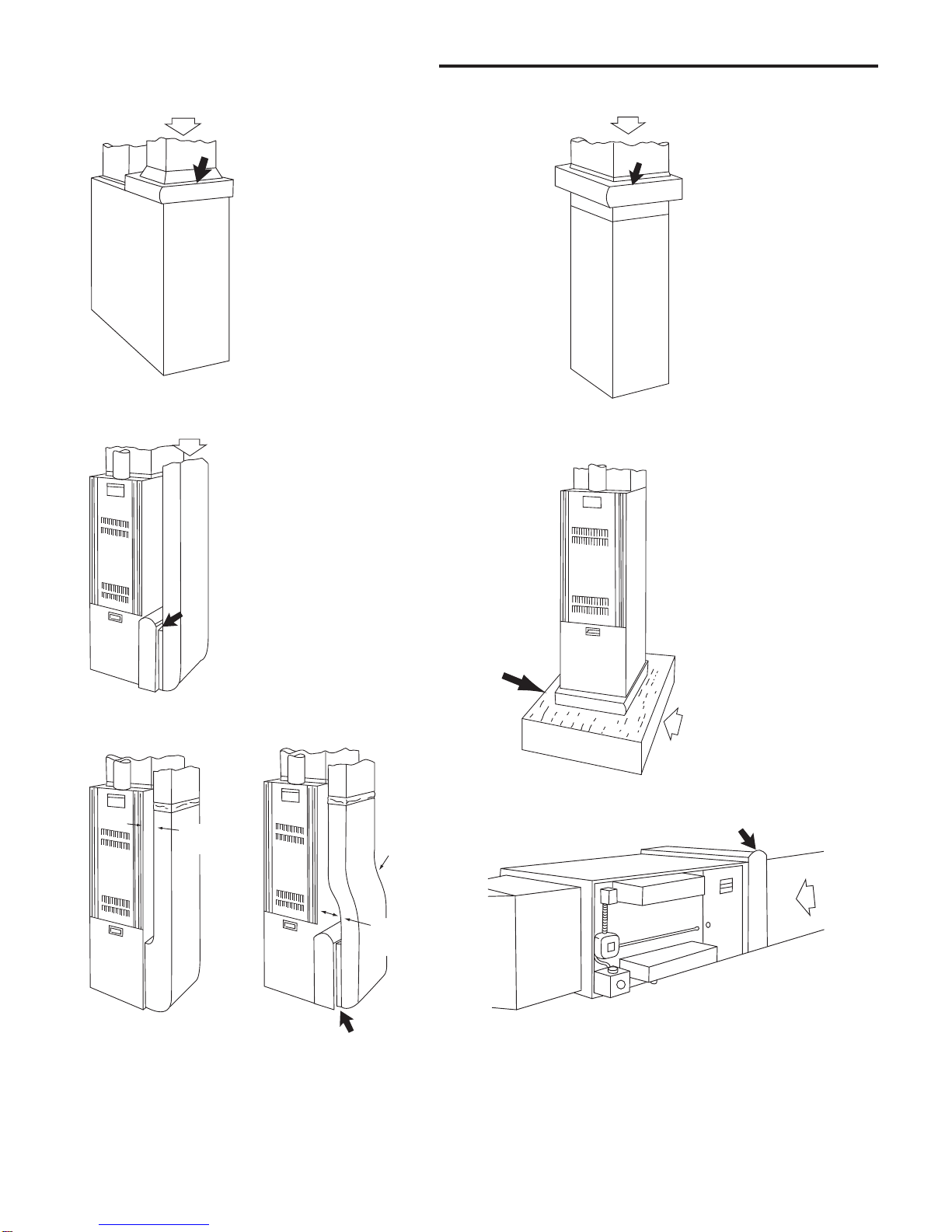
INSTALLATION
The following is a typical installation of the air filter on a
“Highboy” furnace (Figure 7).
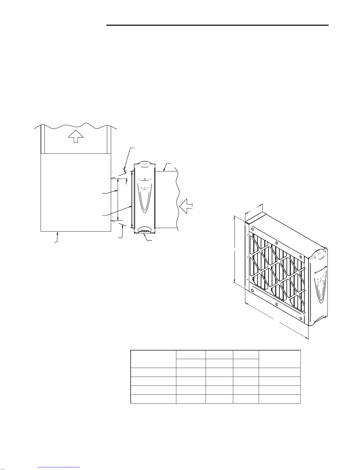
1. Place the air filter compartment on the floor. Stand it upright
with the door facing you (Figure 2). If a horizontal installation
is being planned, lay the compartment on its side, this will
help you to visualize the relative location of all parts.
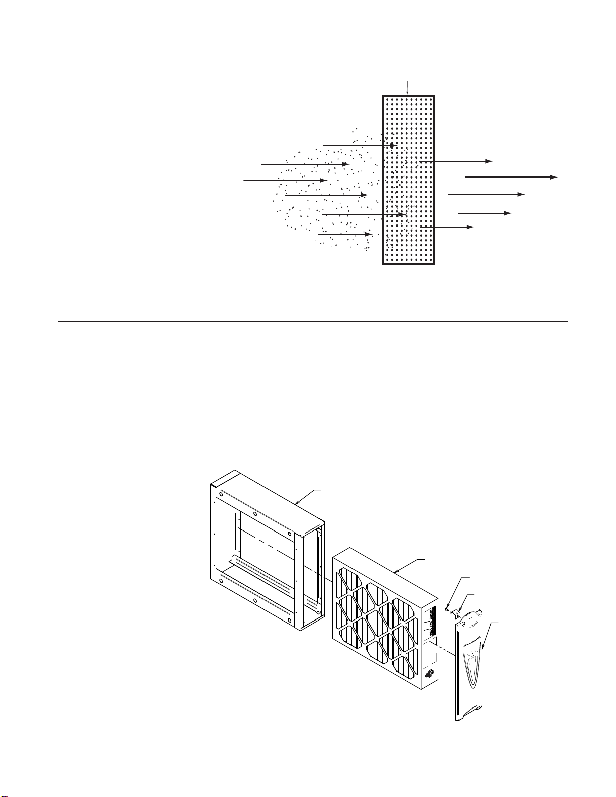
2. Remove the door (by grasping top and pulling door away
from compartment) and set it aside. Remove 4” filter by
grasping it at the top and bottom. Set in a safe location until
the cabinet is installed.
3. Set the compartment next to the furnace (if possible) to
match the opening in the compartment.
If the furnace opening cannot be enlarged, a transition
fitting should be used. (Figure 3).
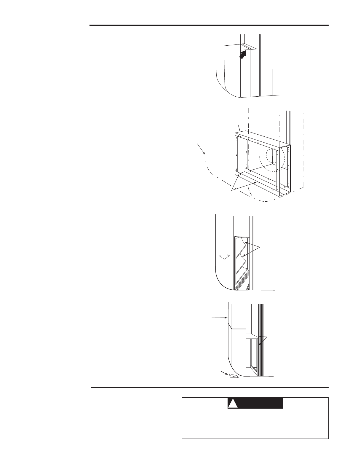
The compartment can be attached directly (Figure 12), or a
starting collar can first be fitted to the furnace inlet. A butt or
slip joint can be used.
Securely attach the compartment to furnace inlet, using
at least two of the mounting holes on each side of the
compartment.
4. Using butt joint, attach duct work (normally an elbow) to the
upstream side of air filter compartment. (Note the use of the
sheet metal turning vanes inside the elbow to improve air
distribution.) (Figure 13)
Transition Fittings
If the air duct does not fit the compartment opening, a transition
fitting should be used. Gradual transitions are preferred for
greatest efficiency. Not more than four inches per linear foot
(approximately 20° angle) should be allowed (Figure 3).
5. Connect the vertical duct section to the elbow.Wedge a wood
block between floor and elbow for support (Figure 14).
6. Seal all joints in the return air system downstream from the
air filter with duct tape to prevent dust from entering the air
stream. Tape is usually applied on the outside of ducts, but
may also be applied on the inside, or both.
7. With the air filter compartment installed, re-install 4” filter
and door. (Figure 2)
MAINTENANCE
The fiber filter used in this cabinet for air cleaning
must be replaced every 90 to 180 days. Your heating
and cooling efficiency will decrease due to insufficient
air flow when filter becomes dirty.
CAUTION
!
For maximum efficiency, your air filter should be inspected once
a month and changed if dirt loading is heavy. When changing is
required, the following procedure should be used.
1. Remove door from air filter compartment.
2. Remove 4” filter and discard.
3. Insert new 4” filter by sliding it into the compartment.
(Note direction of air flow.)
4. Replace door.
Figure 11
Figure 12
Turning
Vanes
Air Flow
Figure 13
Vertical
Section
Wood Block
Tape All
Joints
Figure 14
Duct
Mounting
Holes
Frame

7
NOTES

www.white-rodgers.com
White-Rodgers is a division
of Emerson Electric Co.
The Emerson logo is a
trademark and service mark
of Emerson Electric Co.
This manual suits for next models
7
Table of contents
Other Emerson Air Cleaner manuals

Emerson
Emerson SC-500 Specification sheet

Emerson
Emerson 20C13T-41002 Manual

Emerson
Emerson SC-500 Specification sheet

Emerson
Emerson White Rodgers TTW1000 User manual

Emerson
Emerson 10C17E-41000 Specification sheet

Emerson
Emerson 10C17E-41000 Specification sheet

Emerson
Emerson White-Rodgers MCS600W User manual

Emerson
Emerson 8C11Y-41002 User manual

Emerson
Emerson 20X12A-41001 User manual

Emerson
Emerson ACM1600M-108 User manual