Emerson White Rodgers TTW1000 User manual

Part No. 37-6365A
0530
Model NumbersModel Numbers
Model Numbers
TTW1000TTW1000
TTW1000TTW1000
TTW1000
TTW1400TTW1400
TTW1400TTW1400
TTW1400
TTW2000TTW2000
TTW2000TTW2000
TTW2000
OWNERS MANUALOWNERS MANUAL
OWNERS MANUAL
•InstallationInstallation
InstallationInstallation
Installation
•OperationOperation
OperationOperation
Operation
•ServiceService
ServiceService
Service
TT
TT
Thrhr
hrhr
hru–Tu–T
u–Tu–T
u–The–Whe–W
he–Whe–W
he–Wallall
allall
all
ElectrElectr
ElectrElectr
Electroniconic
oniconic
onic Air CleanerAir Cleaner
Air CleanerAir Cleaner
Air Cleaner
Please read and familiarize yourself with the contents of this manual beforePlease read and familiarize yourself with the contents of this manual before
Please read and familiarize yourself with the contents of this manual before
installing, operating or performing maintenance on the unit.installing, operating or performing maintenance on the unit.
installing, operating or performing maintenance on the unit.
White-Rodgers is a division
of Emerson Electric Co.
www.white-rodgers.com

2
RULES FOR SAFERULES FOR SAFE
RULES FOR SAFE
INSTALLATION AND OPERATIONINSTALLATION AND OPERATION
INSTALLATION AND OPERATION
Please read instructions before installing and using the
Electronic Air Cleaner. This will help you obtain the full
benefit from the Electronic Air Cleaner you have selected.
1. Read the Owners Manual and the Rules for Safe
Operation carefully. Failure to follow these rules and
instructions could cause a malfunction of the air cleaner
or unsatisfactory service.
▲
!WARNINGWARNING
WARNINGWARNING
WARNING
Do not attempt installation of this unit unless youDo not attempt installation of this unit unless you
Do not attempt installation of this unit unless you
are familiar with the necessary tools, equipment,are familiar with the necessary tools, equipment,
are familiar with the necessary tools, equipment,
utility connections and potential hazards.utility connections and potential hazards.
utility connections and potential hazards.
Installation should be performed only by a qualifiedInstallation should be performed only by a qualified
Installation should be performed only by a qualified
service provider.service provider.
service provider.
Failure to do so could result in reduced perfor-Failure to do so could result in reduced perfor-
Failure to do so could result in reduced perfor-
mance of the unit, serious personal injury or death.mance of the unit, serious personal injury or death.
mance of the unit, serious personal injury or death.
▲
!WARNINGWARNING
WARNINGWARNING
WARNING
Installation of this unit must comply with localInstallation of this unit must comply with local
Installation of this unit must comply with local
electric codes or other applicable codes.electric codes or other applicable codes.
electric codes or other applicable codes.
Review and understand local codes prior toReview and understand local codes prior to
Review and understand local codes prior to
installation.installation.
installation.
Do not use this apparatus in an explosiveDo not use this apparatus in an explosive
Do not use this apparatus in an explosive
atmosphere.atmosphere.
atmosphere.
Failure to do so could result in serious personalFailure to do so could result in serious personal
Failure to do so could result in serious personal
injury or death.injury or death.
injury or death.
2. Follow a regular service and maintenance schedule
for efficient operation.
3. Unit must run for one full hour after installation. This will
allow the collecting cells to reach peak efficiency.
Table of ContentsTable of Contents
Table of Contents
Rules for Safe Installation and Operation......2
Introduction ....................................................2
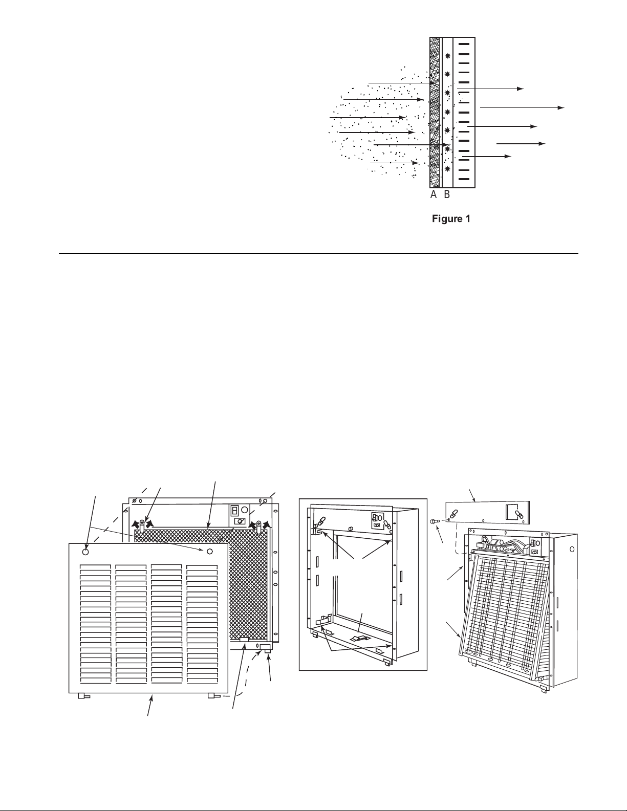
How Your Air Cleaner Works.........................3
Unpacking and Inspection .............................3
Preinstallation ................................................4
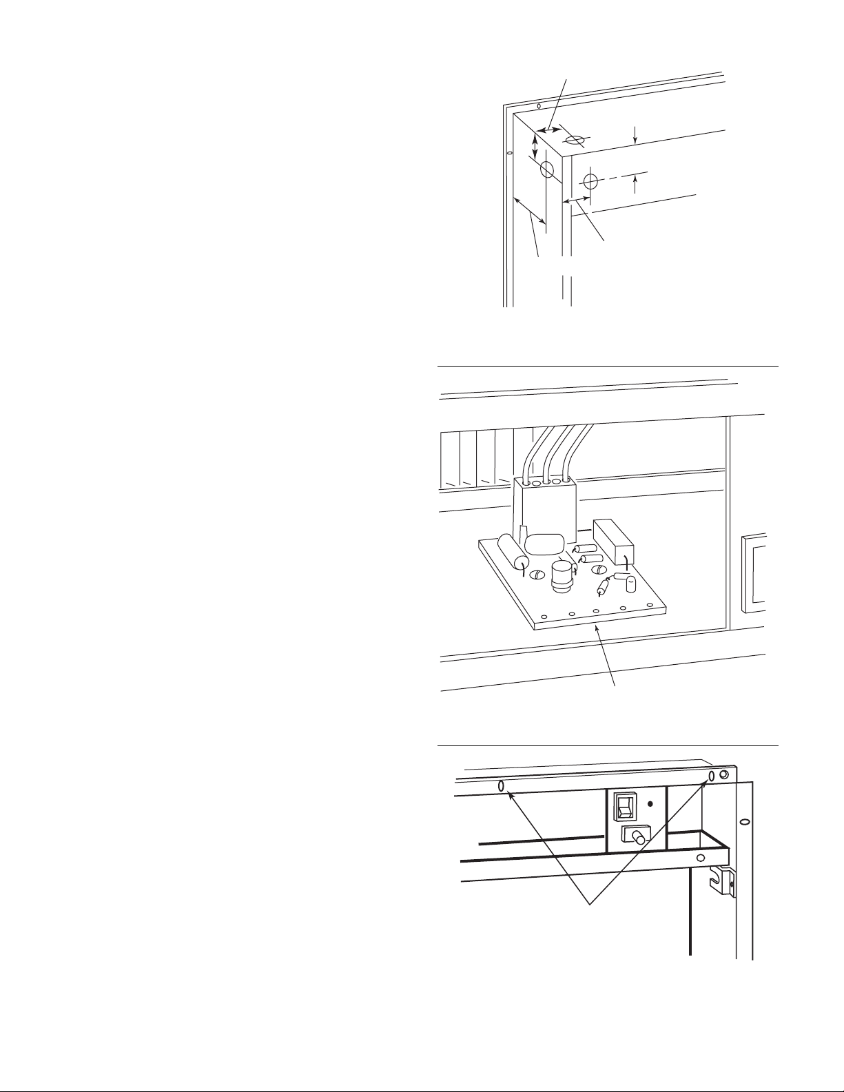
Installation .....................................................6
Operation .......................................................9
Maintenance ..................................................9
Service Hints ...............................................11
Repair Parts.................................................12
Wash Reminder ...........................................14
AIR CLEANER SIZINGAIR CLEANER SIZING
AIR CLEANER SIZING
The units are available in three models:
Model TTW1000Model TTW1000
Model TTW1000
designed for an air volume of up to 1,000 CFM
Model TTW1400Model TTW1400
Model TTW1400
designed for an air volume of up to 1,400 CFM
Model TTW2000Model TTW2000
Model TTW2000
designed for an air volume of up to 2,000 CFM
Shut off power at fuse panel beforeShut off power at fuse panel before
Shut off power at fuse panel before
servicing. Failure to do so could resultservicing. Failure to do so could result
servicing. Failure to do so could result
in serious personal injury or death.in serious personal injury or death.
in serious personal injury or death.
ELECTROCUTION HAZARDELECTROCUTION HAZARD
ELECTROCUTION HAZARD
▲
!WARNINGWARNING
WARNINGWARNING
WARNING
▲
!CAUTIONCAUTION
CAUTIONCAUTION
CAUTION
CABINET AND CELLS MAY CONTAINCABINET AND CELLS MAY CONTAIN
CABINET AND CELLS MAY CONTAIN
SHARP EDGES.SHARP EDGES.
SHARP EDGES.
Use care when servicing unit or handl-Use care when servicing unit or handl-
Use care when servicing unit or handl-
ing cells. Failure to do so could result ining cells. Failure to do so could result in
ing cells. Failure to do so could result in
minor personal injury.minor personal injury.
minor personal injury.
TTW Thru-The-Wall Electronic Air CleanerTTW Thru-The-Wall Electronic Air Cleaner
TTW Thru-The-Wall Electronic Air Cleaner
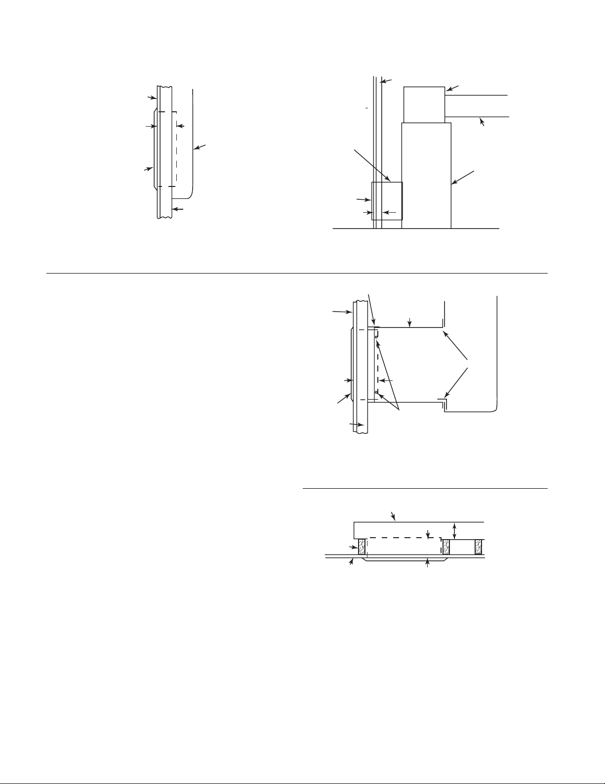
Thru-The-Wall electronic air cleaners are designed to
provide maximum air cleaning in applications where a
single central return air duct is employed, or where the
central heating or air conditioning is in a limited access
area. The Thru-The-Wall units may be installed in the wall
such as in closet installations or in the ceiling with attic type
installations.
INTRODUCTIONINTRODUCTION
INTRODUCTION
This manual contains essential information for locating,
installing, operating and servicing your electronic air
cleaner. Before installing and using your air cleaner, be
sure to read these instructions carefully and observe them
in order to derive the maximum benefits from the superior
performance built into the unit and help to avoid needless
service costs that result from causes the manufacturer
cannot control and cannot be covered in the warranty.

3
GRILLE SCREEN CLIP
HINGE
KNURLED SCREWS
SCREEN RETAINER
LATCH SCREEN
SLOTS FOR CELL
RETAINING PINS
SAFETY
SPRING CLIP
B
A
SPRING CLIPS
SCREW
CABINET
CELL
ELECTRICAL ENCLOSURE COVER
Figure 2
Figure 3
Figure 1
A B C
6. Grasp the two spring clips at the points (A, Fig. 3)
and pull the cell out at the bottom. The collection
cell will move outward approximately three inches
where it will be retained by the safety spring clip at
location (B, Fig. 3). Depress this safety spring clip
to free the cell at the bottom.
7. Grasp the cell at both sides and tilt it rearward at
the top to slide the retaining pins out of their slots
and lift the cell out of the cabinet. Place cell in a
safe location.
UNPACKING AND INSPECTIONUNPACKING AND INSPECTION
UNPACKING AND INSPECTION
1. Unpack and carefully remove air cleaner from
carton.
2. Stand air cleaner upright on floor.
3. Release two knurled screws (Fig. 2) at upper edge
of grille, open grille and slide it out of hinges at
bottom by moving it to the left.
4. Rotate two screen retainer latches either left or
right to clear screen. Lift screen out.
5. Remove three screws, one at each end and one at
center of electrical enclosure cover and remove
cover.
Dirt laden air enters the unit from the room. It passes
through the screen (A) first where large particles (hair,
lint, etc.) are trapped. Smaller particles (smoke, dust,
pollen, etc.) pass through this screen and enter the
Ionizing Section (B). Here each tiny particle receives a
positive electrical charge. These charged particles then
enter the Collection Section (C) which consists of a
series of aluminum plates...alternate plates are
charged positive. See Figure 1.
The positive charged particles are repelled by the
positive plates and attracted to the negative plates
where they are collected — just as a magnet attracts
iron filings.
HOW YOUR AIR CLEANER WORKSHOW YOUR AIR CLEANER WORKS
HOW YOUR AIR CLEANER WORKS

4
WALL SURFACE
6 IN.
AIR CLEANER
RETURN-AIR
DUCT
STUD
WALL SURFACE
RETURN-AIR
DUCT
AIR
CLEANER
6 IN.
STUD SUPPLY-AIR
PLENUM
SUPPLY-AIR
DUCT
FURNACE
TYPICAL INSTALLATION USING DUCT EXTENSION
Figure 5
6 IN.
AIR CLEANER
STUD SCREW HOLES
(TOP, BOTTOM AND
SIDES OF CABINET)
TAPE RETURN-AIR
DUCT
TAPE JOINT
WALL
(OR CEILING)
SURFACE
CONNECTING
DUCT
TYPICAL INSTALLATION USING DUCT EXTENSION
Figure 6
RETURN-AIR DUCT
JOIST
CEILING SURFACE 6 IN.
AIR CLEANER
4 IN. MINIMUM
TYPICAL CEILING LOCATION
Figure 7
TYPICAL WALL LOCATION
Figure 4
PREINSTALLATIONPREINSTALLATION
PREINSTALLATION
LOCATING THE AIR CLEANERLOCATING THE AIR CLEANER
LOCATING THE AIR CLEANER
Your Thru-The-Wall Electronic Air Cleaner is mounted
at the return-air duct inlet. (See figures 4 through 7.) It
works equally well in either high or low wall installa-
tions, or in the ceiling. It can be used with any type of
forced-air heating or cooling system.
In most cases, return-air ducts are located just inside
the wall (or ceiling) grille. When the air cleaner is flush
mounted, it will extend through the wall cutout and into
the return-air duct. If the return-air duct is located at a
distance from the wall (or ceiling), extend a connecting
duct to the rear of air cleaner frame with sheet metal
screws.
NOTENOTE
NOTENOTE
NOTE: Always tape all ductwork joints with duct tape
to prevent dirt-laden air from entering ducts.
After deciding upon the exact location, make sure of
the following before cutting out wall or ceiling area:
1. Exact location of return-air duct behind wall (or
ceiling).
2. Location is free of obstructions, such as steel
support beams, piping or electric wiring.
3. Access to inner area for wiring connections.
4. Return-air duct is deep enough to accommodate air
cleaner (6 inches, see figures 4 through 8.)
5. Enough room is left at a corner or wall offset to
permit installation of the grille. (See figure 8.)

5
GRILLE
26"
24-13/16"
D
C
6" 23-5/16"
A
B
3/4"
FRAME
ASSEMBLY REAR VIEW OF GRILLE AND CABINET
TRANSITION
20
APPROX.
DUCT
3 UNITS
UNIT OPENING
1 UNIT
TRANSITION TO CABINET
Figure 10
ALLOW ROOM FOR
GRILLE TO
SWING OUT
CELL
GRILLE
WALL
(OR CEILING) CABINET
Figure 9
Figure 8
MECHANICAL INSTALLATIONMECHANICAL INSTALLATION
MECHANICAL INSTALLATION
Remember that allowance must be made for the grille
to swing down so that the cell can be removed by
pulling it straight out of the cabinet. (Figure 9).
DUCT WORK CONNECTIONDUCT WORK CONNECTION
DUCT WORK CONNECTION
If the duct work to be used is larger or smaller than the
recommended framing sizes, a transition should be
installed between the duct work and the air cleaner to
insure maximum filtering efficiency. The expansion or
contraction rate of the transition should not exceed the
ratio of 1 to 3. (See figure 10.)
Once the duct connection to the framing is completed,
the air cleaner frame (cabinet) may be inserted into the
framing cavity.
Before inserting the cabinet, one of the three knock-
outs (figure 15) should be removed for insertion of the
120 VAC input wiring.
After properly positioning the cabinet, it may be fas-
tened to the framing either by using the mounting holes
in the inside walls of the cabinet or the mounting holes
in the front flanges of the unit.
DIM.DIM.
DIM.DIM.
DIM. 1000 CFM1000 CFM
1000 CFM1000 CFM
1000 CFM 1400 CFM1400 CFM
1400 CFM1400 CFM
1400 CFM 2000 CFM2000 CFM
2000 CFM2000 CFM
2000 CFM
A 16-15/16 23-7/8 28-7/8
B 9-7/16 16-7/16 21-7/16
C 18-7/16 25-3/8 30-3/8
D192631
Refer to page 2 for model numbers
and CFM cross references.

6
EXISTING STUDS
TOE NAIL TOE NAIL
TOE NAIL
ADD STRINGERS AND HEADERS AT SHADED LOCATIONS
A
OPENING
23-7/16"
Figure 13
EXISTING STUDS EXISTING STUDS
NAIL THRU
NAIL THRU
TOE NAIL TOE NAIL
TOE NAIL TOE NAIL
OPENING
23-7/16"
A
ADD STRINGERS AND HEADERS AT SHADED LOCATIONS
Figure 14
TOE NAIL TOE NAIL TOE NAIL TOE NAIL
OPENING
23-7/16"
NAIL THRU
NAIL THRU
EXISTING STUDS
ADD STRINGERS AND HEADERS AT SHADED LOCATIONS
Figure 12
A
HOLES
CUT-OUT MARK
Figure 11
INSTALLATIONINSTALLATION
INSTALLATION
CAUTION: READ INSTRUCTIONS COMPLETELYCAUTION: READ INSTRUCTIONS COMPLETELY
CAUTION: READ INSTRUCTIONS COMPLETELY
BEFORE STARTING THE INSTALLATION.BEFORE STARTING THE INSTALLATION.
BEFORE STARTING THE INSTALLATION.
1. Mark the cutout area. (See figures 8 and 12 through
14 for dimensions.)
2. Drill holes at the corners of area to be cut out to
permit insertion of saw blade. (See figure 11.)
3. Carefully saw out wall or ceiling area exactly as
marked. Remember the frame flange is only 3/4
inch wide. It will not cover an oversize or irregular
cutout.
4. Figures 12, 13 and 14 show several possible
situations that will be apparent when the cutout is
finished. With standard stud spacing you will run
into either one or two studs. They must be cut and
the section removed at air cleaner location.
5. Install headers all around air cleaner opening (four
sides). This will provide good support of air cleaner
and restore the original wall strength. Use basic
concepts shown in figures 12 through 14 if your wall
differs from the diagrams shown.
NOTENOTE
NOTENOTE
NOTE: The same method for framing the air cleaner
cutout can be applied to ceiling joists, when a ceiling
installation is required.
6. Cut out required opening in return-air duct. The duct
cutout should fit air cleaner cabinet as closely as
possible. If duct is more than six inches from wall
surface, install a connecting duct between air
cleaner cabinet and existing duct. (See figures 5
and 6.)
7. Slide the frame assembly into the finished cutout.
Make sure it fits properly, then remove it.
* Dimension “A” in figures 12 through 14 are as follows:
1000 CFM = 17”
1400 CFM = 24”
2000 CFM = 29”

7
1-9/16"
1-1/16"
1-9/16"
4-13/16"
2"
KNOCKOUT
LOCATIONS
Figure 15
AIR FLOW MONITOR
Figure 16
NAILS (OR SCREWS) THROUGH
THESE HOLES (12 LOCATIONS)
Figure 17
8. Prepare air-cleaner cabinet for electrical connection
as follows:
a. Determine location of power supply source
which will dictate the location of electrical wiring.
b. Three knockouts (figure 15) are located in upper
right-hand corner of cabinet. A built-in “J” type
junction box is included. Secure wiring with
accepted hardware.
c. The usual knockout location is at upper rear of
cabinet. If an obstruction prohibits this location,
use either of the two other knockouts.
d. Allow at least 10 inches of wire lengths on inside
of cabinet for connection to air-cleaner wires.
9. Connect air-cleaner to existing wiring.
Wiring to the air cleaner must comply with local
electrical codes. For this reason, specific wiring
instructions are not given. The color coding of wires
out of the junction box are white (120V) or red (220V)
and black. They should be matched to wires of the
same color from electrical power source figure 18).
Connect ground wire from power source directly to
the green grounding wire provided in the junction
box area.
This Thru-The-Wall electronic air cleaner may be
equipped with a solid state Air Flow monitor (figure
16) that will automatically turn your air cleaner ON
or OFF whenever the furnace fan is running.
10. Install frame assembly in wall opening:
a. Slide air cleaner cabinet into wall opening.
b. Secure the cabinet in opening with nails, or
screws, through the 12 holes provided in face
of flange (figure 17), or through holes in cabinet
walls.
CAUTION: On ceiling installations, be sure to
use all 12 flange holes to support full weight of
air cleaner.
c. If an extension duct is required, install it now.
d. Reach through air cleaner cabinet and tape all
joints made into ductwork.

8
RETAINING PIN ARROW MUST
POINT INWARD
CELL
SCREEN
HINGE PIN
GRILLE
SAFETY
SPRING CLIP
SCREEN CLIP
CABINET
CELL RETAINING SLOTS
CHECK
SAFETY LATCH
Figure 20
BLACK
WHITE (120V)
RED (220V) SUPPLY
WHITE (120V)
RED (220 V)
SUPPLY
BLACK (120V or 220V)
SUPPLY GROUND
(GREEN OR BARE)
GREEN GROUND WIRE
Figure 18
11. Connect Power Wires.
a. (120V) Connect black and white wires from power
sourcetocorrespondingblackandwhitewiresinthe
air cleaner junction box. (See figure 18.)
(220V) Connect black and red wires from power
sourcetocorrespondingblackandredwiresinthe
air cleaner junction box. (See figure 18.)
b. Connectgroundwire(greenorbarewire)frompower
source to green grounding wire in junction box.
c. Install electrical enclosure cover with three screws.
(See figure 2.)
12. Install the cell.
a. Grasp the cell firmly, holding it at a slight angle
with the cabinet (out at bottom). The arrow on
top of cell should point inward.
b. Insert cell at the top and engage retaining pins
(figure 19) into their respective cell-retaining
slots, then slide cell outward until retaining pins
are at bottoms of slots.
c. Allow cell to swing inward at the bottom, pushing
slightly until it “clicks” over the safety spring clip
at bottom center of cabinet.
d. Continue to push cell inward at bottom until it
latches into the spring clips (one at each side of
cabinet). Make sure both clips are latched. (See
figure 19.)
13. Install screen and grille.
a. Drop screen behind two screen clips at bottom
of cabinet and fasten at upper edge with two
spring retainer latches. (See figure 2).
b. Engage pins at lower edge of grille into their
mating hinges. Slide grille toward the right until
hinge pins are fully seated.
c. Leave grille open until after operational tests
havebeen performed
CAUTIONCAUTION
CAUTIONCAUTION
CAUTION: When installing the cell on ceiling installa-
tions, make sure it is latched securely in cell frame
before releasing it. (See figure 20.)
Figure 19Figure 19
Figure 19Figure 19
Figure 19

9
RETAINING
SPRING CLIPS
SAFETY
SPRING CLIP
RETAINING
PIN SLOTS
ON-OFF
ROCKER SWITCH
SCREEN RETAINER
LATCHES
KNURLED
SCREWS
SCREEN
ON
OFF
Figure 21
ON-OFF
SWITCH
SAFETY INTERLOCK
SWITCH
OPERATING LIGHT
OPERATIONOPERATION
OPERATIONOPERATION
OPERATION
1. If your unit has an air flow switch, turn on furnace or
air conditioner to get air flow through the duct.
(Unit without switch, move to step 2.)
2. Press the upper section of “ON-OFF” rocker switch
(figure 21).
3. Close the grille by rotating into position on the
cabinet (figure 19). Lock in position with two
knurled screws.
NOTENOTE
NOTENOTE
NOTE: If your air cleaner is equipped with an air
sensing device, it may provide a short delay before the
operating light comes on.
IMPORTANTIMPORTANT
IMPORTANTIMPORTANT
IMPORTANT: Occasionally, you will hear a sharp
snapping sound (called arcing) coming from the air
cleaner. Arcing is a normal phenomenon. It can result
from the collection of especially large particles. It
occurs more often in a new installation. Later on,
arcing may occur when the cell has become loaded
with dirt and needs washing, or when still damp after
washing. The presence (or absence) of this sound
normally does not mean that the unit is defective.
MAINTENANCEMAINTENANCE
MAINTENANCE
WASHING CELL AND SCREENWASHING CELL AND SCREEN
WASHING CELL AND SCREEN
NOTENOTE
NOTENOTE
NOTE: For top performance your electronic air cleaner
should be cleaned at least every two months, or more
often in areas of extreme airborne dust.
1. Remove two knurled screws and open the grille.
2. Push “ON-OFF” rocker switch at bottom to turn it
off (figure 21). Wait 15 seconds.
3. Rotate two screen retainer latches either left or right
to clear screen. Lift screen out.
4. Release the two retaining spring clips (one at each
side, figure 22) and pull cell outward at bottom until
it is stopped by the safety spring clip at bottom
center of cabinet.
5. Release safety spring clip and pull cell outward at
bottom until it swings free.
6. Tilt cell outward at bottom and slide it inward at the
top to release the two retaining pins from their slots
in cabinet. Place cell in a safe location.
Figure 22Figure 22
Figure 22Figure 22
Figure 22

10
7. PREPARE THE WASH WATER:
a. Place enough hot water in a suitable wash
container (figure 23) to cover the cell.
b. Dissolve four ounces of automatic dishwasher
detergent, such as Calgonite, in the water.
Liquid detergents used to wash dishes by hand
are not strong enough for good cleaning.
c. Shake the screen gently outside the house to
remove heavy dirt collections.
8. SOAK:
a. Lay the cell in the container and allow it to soak
for thirty minutes.
b. Then slosh the cell up and down in the solution
until it appears clean. Remove cell from the
container.
c. Ionizing wires may become coated, causing loss
of cleaning ability by the collecting cell. Using a
damp cloth, wipe each ionizing wire, exercising
care not to damage them.
d. Then slosh the screen up and down in the
solution until clean. Drain out the dirty water.
9. RINSE:
a. Hold cell upright in container.
b. With a hose, rinse with warm water. (See
figure 24.)
c. The hose nozzle should be held approximately
ten inches from cell plates and at a slight angle
for better cleaning effect. Rinse both sides of
cell until water is clear.
d. Flush cell frame along edges to dislodge any
trapped dirt or lint.
e. Flush and rinse screen on both sides.
f. Stand cell and screen up and allow them to
drain for 2 hours.
10. WHITE DUST (LINT)
An Electronic Air Cleaner is designed to collect two
major types of contaminants:
a. Irritants (Pollens Spores, Molds, Bacteria, etc.)
b. Black soiling contaminants (Dirt and Smoke
particles.)
The residue on the collecting plates of an electronic air
cleaner is black, indicating it is removing dirt from the
air stream. After installing an air cleaner you may
notice white dust (typically long linty particles or fibers:
from carpets, cotton materials or drapery fabrics.) This
material is not collected by the air cleaner because it
does not contain the irritants or soiling contaminants
listed above or settles out of the air before reaching the
air cleaner. The presence of white dust does not
indicate an air cleaner requires service.
11. INSTALL CELL
CAUTIONCAUTION
CAUTIONCAUTION
CAUTION: When installing the cell in a ceiling installa-
tion, make sure it is latched securely in place before
releasing it. (See figure 20.)
a. Grasp the cell firmly, holding it at a slight angle
with the cabinet (out at bottom). The arrow on
top of cell should point inward.
b. Insert cell at the top and engage retaining pins
(figure 19) into their respective cell retaining
slots, then slide cell outward until retaining pins
are at bottoms of slots.
c. Allow cell to swing inward at the bottom, pushing
slightly until it “clicks” over the safety spring clip
at bottom center of cabinet.
d. Continue to push cell inward at bottom until it
latches into the spring clips (one at each side of
cabinet). Make sure both clips are latched. (See
figure 19.)
e. Press the lower section of the “ON-OFF” switch
to turn unit on.
f. Replace the screen. Close the grille and secure
it with the two knurled screws.
Figure 23Figure 23
Figure 23Figure 23
Figure 23
Figure 24Figure 24
Figure 24Figure 24
Figure 24

11
SUPPORT
IONIZING
WIRE
INDICATIONINDICATION
INDICATION CORRECTIVE PROCEDURESCORRECTIVE PROCEDURES
CORRECTIVE PROCEDURESCORRECTIVE PROCEDURES
CORRECTIVE PROCEDURES
• ON-OFF Switch Light on 1. Electric power is being supplied to the air cleaner and the unit is functioning
– Operating Light on.
• ON-OFF Switch Light off 1. Electric power is not being supplied to the air cleaner.
– Operating light off a. See that system fan is operating.
b. Check fuse or circuit breaker in main circuit control box.
c. Check ON-OFF switch for ON position.
• ON-OFF Switch Light on 1. Large foreign object might be lodged between collective plate of cell.
– Operating Light off. a. Remove cell and wash thoroughly.
2. Broken ionizing wire.
a. Install a new wire as outlined above.
3. Malfunction in electric power supply.
a. Notify your Service Man.
SERVICE HINTSSERVICE HINTS
SERVICE HINTS
The following instructions are for use by qualified personnel. WARNING: The following procedures willThe following instructions are for use by qualified personnel. WARNING: The following procedures will
The following instructions are for use by qualified personnel. WARNING: The following procedures will
expose hazardous live parts. Disconnect electrical power to air cleaner before proceeding.expose hazardous live parts. Disconnect electrical power to air cleaner before proceeding.
expose hazardous live parts. Disconnect electrical power to air cleaner before proceeding.
REPLACING AN IONIZING WIREREPLACING AN IONIZING WIRE
REPLACING AN IONIZING WIRE
If one or more ionizing wires in the cell should break,
usually caused by accidental damage, it can be
replaced as follows:
1. Remove all pieces of broken wire. Make sure
supports at each end are in good condition and not
bent out of shape.
2. Hook the wire at one end onto the support.
3. Hold a finger against the support at other end
(figure 25) and hold ionizing wire between thumb
and forefinger as shown. Press on spring and push
on wire loop until it slips over end of support. Make
sure wire is securely anchored at each end.
Figure 25Figure 25
Figure 25Figure 25
Figure 25

12
REPLACEMENTREPLACEMENT
REPLACEMENT
PARTS DIAGRAMPARTS DIAGRAM
PARTS DIAGRAM
1 or 1
32
5
7
6
9
5
10
11
8
120V
220V

13
ITEM NOITEM NO
ITEM NOITEM NO
ITEM NO..
..
.DESCRIPTIONDESCRIPTION
DESCRIPTIONDESCRIPTION
DESCRIPTION TTW1000TTW1000
TTW1000TTW1000
TTW1000 TTW1400TTW1400
TTW1400TTW1400
TTW1400 TTW2000TTW2000
TTW2000TTW2000
TTW2000
1 (120V) Power Supply Assembly and Air Switch Assembly F858-1002 F858-1002 F858-1002
(220V) Power Supply Assembly with 5088D-001 5088D-001 5088D-001
220V Transformer F146-0644 F146-0644 F146-0644
2 Switch (ON-OFF) F876-0202 F876-0202 F876-0202
3 Switch, Safety F876-0199 F876-0199 F876-0199
4 Operating Light F844-0130 F844-0130 F844-0130
5 Cell Assembly F811-0437 F811-0438 F811-0439
6 Ionizing Wire F843-0775 F843-0775 F843-0775
7 Pre-Filter F121-0232 F121-0233 F121-0234
8 Screw, with Washer F870-0026 F870-0026 F870-0026
9 Grille F831-0095 F831-0096 F831-0097
10 Charcoal Filter F121-0235 F121-0236 F121-0237
††
††
† Manual 37-6365 37-6365 37-6365
††
††
† Not Shown
Parts List for Electronic Air Cleaner TTWParts List for Electronic Air Cleaner TTW
Parts List for Electronic Air Cleaner TTW
ORDERING INFORMATIONORDERING INFORMATION
ORDERING INFORMATION
When purchasing equipment or replacement parts from
your Distributor, use the Parts List. Always include com-
plete unit model number, part number and description
with your parts order.
WHITE-RODGERS SALES DEPARTMENT
St. Louis, Missouri 63136

14
Year JAN FEB MAR APR MAY JUN JUL AUG SEP OCT NOV DEC
20___
20___
20___
20___
20___
20___
20___
20___
20___
20___
20___
20___
20___
20___
20___
20___
20___
20___
20___
20___
20___
20___
20___
WASH REMINDER SCHEDULEWASH REMINDER SCHEDULE
WASH REMINDER SCHEDULE
A regular washing schedule is necessary to ensure
proper efficiency. A thorough washing once every
month will be adequate for most installations. More or
Less frequent washing may be necessary on some
installations where there is new carpeting, plaster dust
or excessive cigarette smoke, etc. (See page 9 for
maintenance and instructions on how to clean a cell.)

15

NOTICE TO CONSUMERSNOTICE TO CONSUMERS
NOTICE TO CONSUMERS
White-Rodgers
Electronic Air Cleaner
Dear Consumer;
White-Rodgers would like to thank you for purchasing a White-Rodgers Electronic Air
Cleaner or product containing a White-Rodgers Electronic Air Cleaner. Although White-
Rodgers does not extend a warranty directly to consumers, White-Rodgers does extend a
warranty to Wholesalers and Original Equipment Manufacturers who use White-Rodgers
Products. To obtain more information about how your Wholesaler or Original Equipment
Manufacturer’s warranty may benefit you, please contact your Wholesaler or Original
Equipment Manufacturer.
Sincerely,
White-Rodgers
The Emerson logo is a
trademark and service mark
of Emerson Electric Co.
This manual suits for next models
2
Table of contents
Other Emerson Air Cleaner manuals

Emerson
Emerson 10C18E-41000 Specification sheet

Emerson
Emerson White-Rodgers MCS600W User manual

Emerson
Emerson 10C17E-41000 Specification sheet

Emerson
Emerson SC-500 Specification sheet

Emerson
Emerson ACM1600M-108 User manual

Emerson
Emerson 20C13T-41002 Manual

Emerson
Emerson 20X12A-41001 User manual

Emerson
Emerson 8C11Y-41002 User manual

Emerson
Emerson MEDIA AIR CLEANER ACM1000M-XXX User manual

Emerson
Emerson SC-500 Specification sheet