Pour réduire le risque de blessures graves si l’échelle tombe ou si elle est projetée en cas de freinage brusque ou d’accident :
• Lisez et suivez toutes les instructions et les avertissements avant d’installer ou d’utiliser ce produit.
• Le porte-échelle coulissant ne doit être utilisé que pour transporter les échelles. Ne modifiez ou n’utilisez jamais le porte-échelle coulissant à
toute autre fin.
• Le porte-échelle doit être installé selon les instructions.
• Montez le porte-échelle coulissant seulement dans une fourgonnette, une remorque fermée ou un toit de caisse en métal.
• Le poids maximum de l’échelle ne doit pas dépasser 80lb.
• Lors de l’utilisation d’outils électriques, suivez les avertissements et les instructions du fabricant des outils.
• Protégez vos yeux. Portez des lunettes de sécurité conformes à la norme ANSI Z87.1 (ou au Canada, CSA Z94-3-M88) tel qu’indiqué
sur l’emballage.
• N’installez jamais le système de porte-échelle coulissant à l’intérieur des compartiments passagers.
• Vérifiez le câblage électrique dans les endroits où les trous seront percés. Consultez le manuel de service du véhicule pour les directions
de câblage.
8
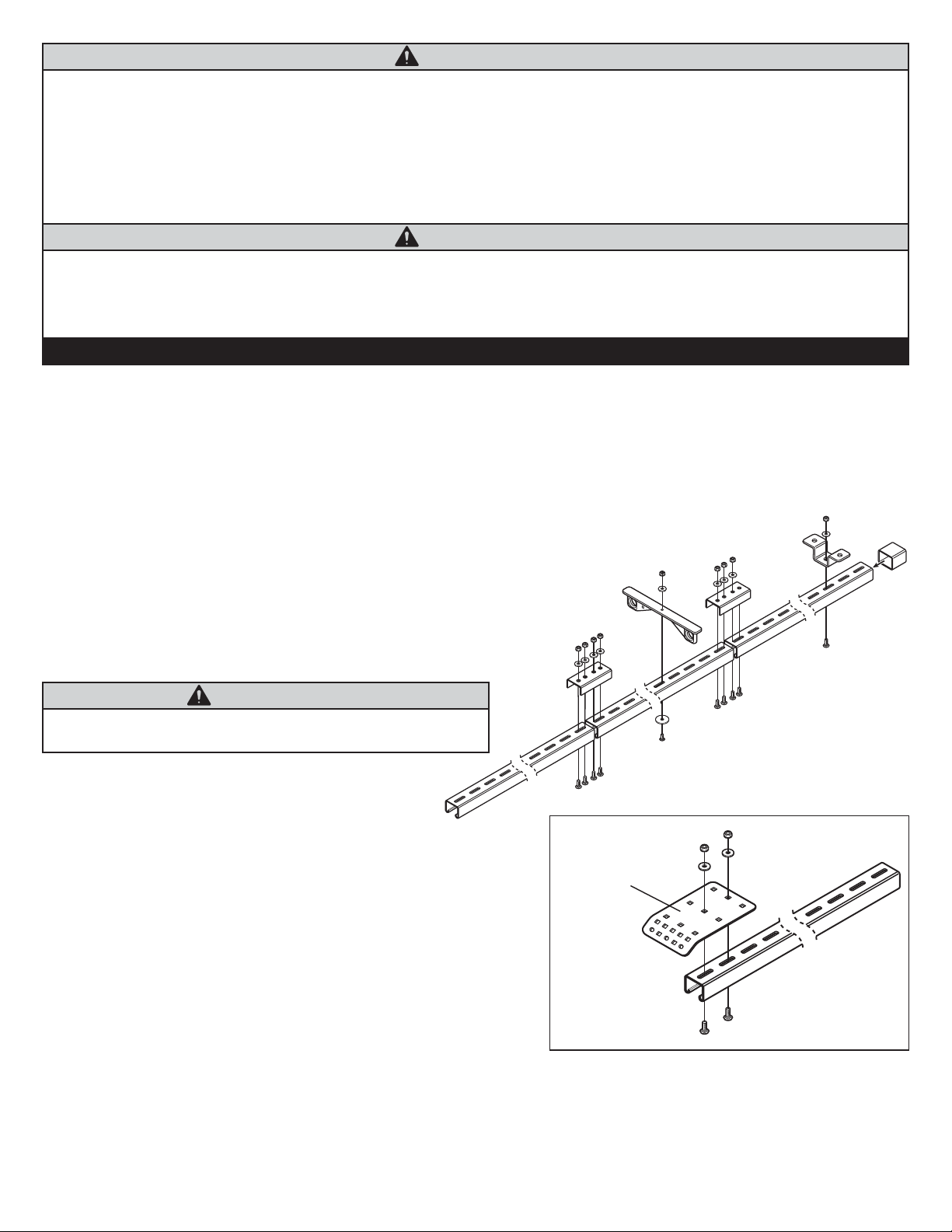
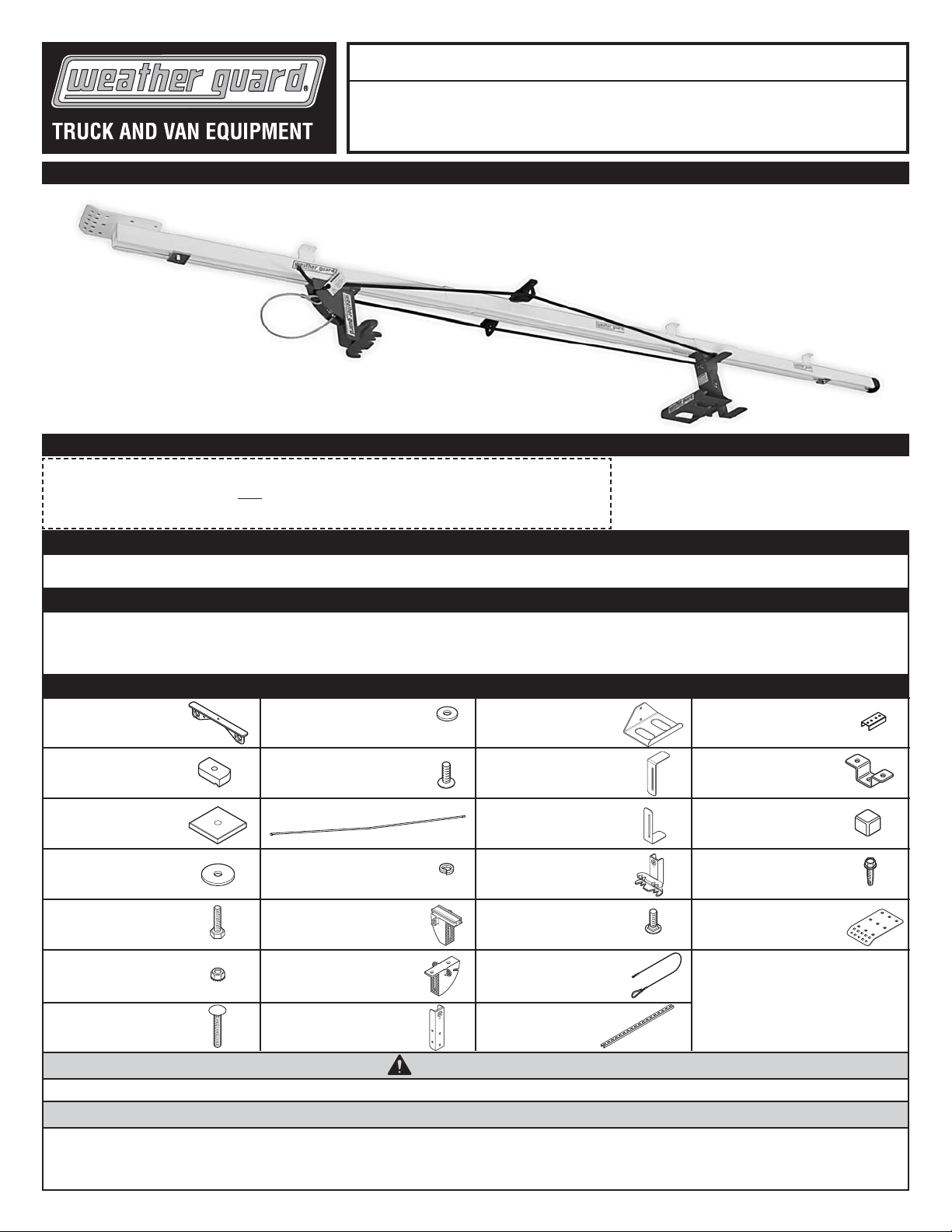
Étape 1 : INSTALLATION D’ASSEMBLAGE DE LA TRAVERSE
Utilisez les fixations de raccord (2), raccordez les sections de
traverse (3) à l’aide de à l'aide de huit boulons de carroserie de
1/4-20 x 3/4”, des rondelles plates de 1/4” et des contre-écrous
de nylon de 1/4-20.
REMARQUE : les instructions d’installation suivantes sont écrites
pour l’installation de ce produit aux nervures du toit de caisse d’une
fourgonnette ou d’un camion. Ce support se monte sur la paroi
latérale d’une remorque, si désiré, en utilisant les mêmes étapes
décrites plus bas.
REMARQUE : selon la taille et le type de votre véhicule, il faudra
peut-être couper la traverse à la bonne longueur.
Mesurez la distance à l’intérieur de la fourgonnette et coupez
la traverse assemblée à la bonne longueur.
Déterminez l’emplacement de montage de la traverse à l’intérieur du
véhicule (centre, décentré, côté). Mesurez l’emplacement des trois
premières nervures de l’arrière de la fourgonnette en commençant
par le côté intérieur supérieur de l’embrasure de porte arrière et en
mesurant vers l’avant. Notez ces dimensions.
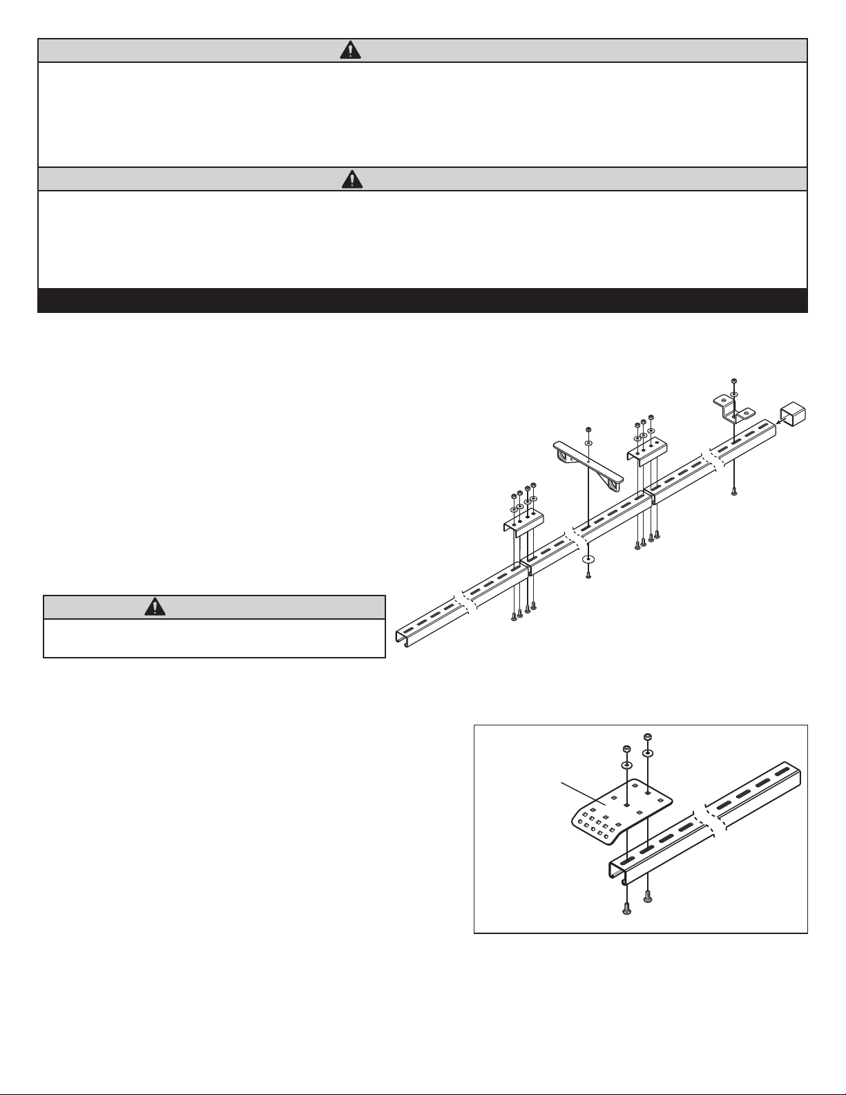
Attachez la fixation de montage arrière à l’arrière de la traverse
(l’extrémité opposée à celle ayant été coupée) en utilisant deux
boulons de carrosserie de 1/4-20 x 3/4”, rondelles plates de 1/4”
et des contre-écrous de nylon de 1/4-20. Voir la figure 1a.
De l’arrière de la fixation de montage arrière, marquez l’assemblage de
la traverse à l’emplacement inscrit des nervures. Vissez une fixation de
montage juste assez serrée pour l’ajuster à la main, centrée sur chaque
marque et en utilisant un boulon de carrosserie de 1/4-20 x 3/4”, une
rondelle plate de 1/4” et un contre-écrou de nylon de 1/4-20.
Placez l’assemblage de la traverse dans le véhicule en position.
Déterminez si la fixation de montage arrière doit être modifiée.
Vous pouvez la décentrer par rapport à l’assemblage de la traverse
ou en retirer une partie ou encore, modifier l’angle du rebord pour
faire affleurer le tout à l’embrasure de porte, au besoin. Ajustez au
besoin les emplacements des fixations de montage de l’assemblage
de la traverse pour vous assurer qu’elles sont bien installées sur
les nervures du toit.
Retirez l’assemblage de la traverse des nervures du toit et resserrez
bien les fixations de montage.
Replacez l’assemblage de la traverse en place et fixez-le aux nervures
du toit et à l’embrasure de porte arrière avec deux vis autoperceuses
de 1/4-14 x 3/4” et rondelles plates de 1/4” par fixation.
Attachez le guide-cordon environ 30” à l’arrière de l’assemblage de la
traverse en utilisant une vis de mécanique à tête cylindrique large de
1/4-20 x 7/8”, une rondelle de 1-1/4” de D.E. une rondelle plate 1/4”
et un contre-écrou de nylon de 1/4-20. Ajustez la dimension de 30”
pour les obstructions, au besoin.
INSTRUCTIONS D’INSTALLATION
Figure 1
Figure 1a
AVERTISSEMENT
AVERTISSEMENT