Instruction Manual
D200138X012
3582, 582i, and 3583
January 2013
2
Contents (cont'd)
Valve Positioner Bypass Operation 26.............
Input Signal Ranges 27.........................
Valve Positioner Split‐Range Operation 27.........
Changing Valve Positioner Action 28.............
Changing Valve Stem Position Transmitter
Action 28..................................
Calibration Of Valve Positioner Or
Valve Stem Position Transmitter 29................
Beam Alignment 29...........................
Calibration 31................................
Principle of Operation 32........................
3582 Valve Positioners 32......................
3582i Valve Positioner 33.......................
3583 Valve Stem Position Transmitters 34.........
Maintenance 35................................
Changing the Range Spring 36..................
Replacing Gaskets 36..........................
Replacing the Nozzle O‐Ring 37..................
Replacing the Relay 37.........................
Adjusting the Flapper Pivot 38...................
Replacing the 582i Converter
Primary O‐Ring and Filter 38..................
Replacing the 582i Converter Housing
Cap O‐Ring 38..............................
Removing the 582i Converter 38.................
Reassembling the 582i Converter 39.............
Parts Ordering 40...............................
Parts Kits 40...................................
Parts List 41...................................
Loop Schematics/Nameplates 54.................
Introduction
Scope of Manual
This instruction manual includes installation, operation, calibration, maintenance, and parts ordering information for
Fisher 3582 pneumatic valve positioners, the 3582i electro‐pneumatic valve positioner, and 3583 pneumatic valve
stem position transmitters. Refer to separate instruction manuals for information on the control valve, actuator, and
accessories.
Do not install, operate or maintain a 3582 pneumatic valve positioner, a 3582i electro‐pneumatic valve positioner, or a
3583 pneumatic valve stem position transmitter without being fully trained and qualified in valve, actuator and
accessory installation, operation and maintenance. To avoid personal injury or property damage it is important to
carefully read, understand, and follow all of the contents of this manual, including all safety cautions and warnings. If
you have any questions about these instructions, contact your Emerson Process Management sales office before
proceeding.
Description
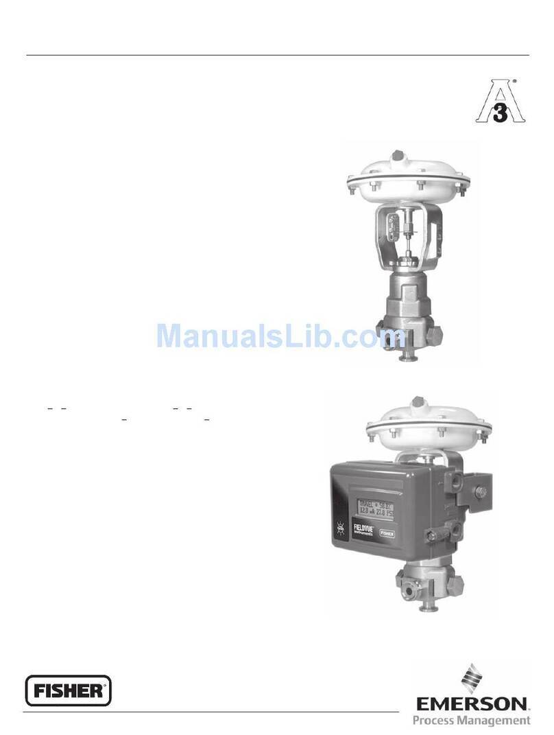
3582 pneumatic valve positioners and the 3582i electro‐pneumatic valve positioner shown in figure 1 are used with
diaphragm‐actuated, sliding‐stem control valve assemblies. The pneumatic valve positioners receive a pneumatic
input signal from a control device and modulate the supply pressure to the control valve actuator. The positioner
adjusts the actuator supply pressure to maintain a valve stem position proportional to the pneumatic input signal.
3582NS positioners are designed for nuclear power applications. The 3582NS construction includes materials that
provide superior performance at elevated temperature and radiation levels. The O‐rings are EPDM (ethylene
propylene) and the diaphragms are EPDM/meta‐aramid fabric. EPDM demonstrates superior temperature capability
and shelf life over nitrile. The meta‐aramid diaphragm fabric demonstrates improved strength retention at elevated
temperature and radiation conditions.
CAUTION
Use a clean, dry, oil‐free air supply with instruments containing EPDM components. EPDM is subject to degradation when
exposed to petroleum‐based lubricants.
