manuals.online logo
Brands
  1. Home
  2. •
  3. Brands
  4. •
  5. Emerson
  6. •
  7. Control Unit
  8. •
  9. Emerson Spence K3 User manual

Emerson Spence K3 User manual

▲ WARNING
Failure to follow these instructions or
to properly install and maintain this
equipment could result in an explosion,
re and/or chemical contamination
causing property damage and personal
injury or death.
Emerson Control Valve must be
installed, operated and maintained
in accordance with federal, state and
local codes, rules and regulations
and Emerson Process Management
Regulator Technologies, Inc.
(Emerson) instructions.
If the control valve vents gas or a
leak develops in the system, service
to the unit may be required. Failure
to correct trouble could result in a
hazardous condition.
Installation, operation and maintenance
procedures performed by unqualied
personnel may result in improper
adjustment and unsafe operation. Either
condition may result in equipment
damage or personal injury. Only a
qualied person shall install or service
the Type K3 control valve.
Introduction
Scope of the Manual
This manual provides instructions for the installation,
start-up, setting, maintenance, troubleshooting and
parts ordering for Type K3 control valve.
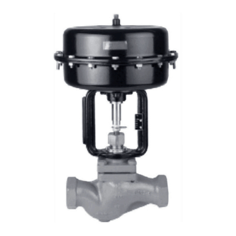
Spence Type K3 Control Valve
Figure 1. Type K3 Control Valve
Product Description
Type K3 control valve is designed for economical
control of steam, water, gas and process applications
in typical institutional, commercial and industrial
processes. Type K3 is a three-way valve available with
either a direct or reverse acting actuator that meets
most mixing or diverting application requirements.
Type K3
Instruction Manual
VCIMD-14940
November 2021
www.SpenceValve.com
Figure 2. Type K3 Pressure and Temperature Chart
Table 1. Approximate Weight
Specications
This section lists the specications for the Type K3. Factory specication are stamped on the nameplate fastened
on the control valve at the factory.
Control Valve Type
Type K3: Three-way valve with union ends and
pneumatic actuator
Control Valve Sizes
NPS 1/2, 3/4, 1, 1-1/4, 1-1/2 and 2 /
DN 15, 20, 25, 32, 40 and 50
Pressure and Temperature Chart(1)/
See Figure 2
Control Pressure Capabilities(1)
3 to 15 psi / 0.21 to 1.03 bar
End Connection Style
CL250
Flow Coe󰀩cient, Cv
NPS 1/2 / DN 15: 5.6
NPS 3/4 / DN 20: 7.1
NPS 1 / DN 25: 9.2
NPS 1-1/4 / DN 32: 22
NPS 1-1/2 / DN 40: 28
NPS 2 / DN 50: 35
Construction Materials
Body: Bronze
Seat: Stainless steel
Plug, Stem and Stem Assembly: Stainless steel
Stem Guide: Stainless steel, Monel or Brass
Actuator Casing: Steel
Actuator Spring: Steel Wire
Diaphragm: Nitrile (NBR)/Polyester
Yoke: Ductile Iron
Options
36 or 60 sq. in. / 0.02 or 0.04 sqm actuators
Electric Actuator
Applicable Codes
Meets or exceeds ANSI B16.15 Class 250
ANSI/FCI 70-2 Class IV Seat Leakage
Article 3, Section 3 of the
Pressure Equipment Directive.
Approximate Weight
See Table 1
VALVE SIZE 36 in. sq /
0.02 sqm
60 in. sq /
0.04 sqm
NPS DN lbs kg lbs kg
1/2 15 28 12.7 41 18.6
3/4 20 28 12.7 41 18.6
1 25 27 12.3 40 18.2
1-1/4 32 35 15.9 48 21.8
1-1/2 40 37 16.8 50 22.7
2 50 42 19.1 55 25
1. The pressure/temperature limits in this Instruction Manual and any applicable standard or code limitation should not be exceeded.
ANSI/ASME B16.15 CLASS 250
SATURATED STEAM
TEMPERATURE, °F
PRESSURE, psi
PRESSURE/TEMPERATURE CHART
2
Type K3
Principle of Operation
Type K3 valve is a three-way, universal construction,
globe style, pneumatic diaphragm control valve. The
pneumatic actuator can be arranged as direct or
reverse acting.
When selecting a direct acting actuator, upper port
is failed closed on air loss. When selecting a reverse
acting actuator, the lower port is failed closed on air
loss. When used for mixing, the forces developed by
the two inlet flows oppose each other and create a
balanced environment. Thus, the actuator can control
the flow efficiently without power lost to over come
dynamic unbalance. When using the valve for diverting
service, simply reverse the valve installation.
Installation
▲ WARNING
Personal injury or system damage may
result if this control valve is installed,
without appropriate overpressure
protection, where service conditions
Figure 3. Fluid Flow Direction for Mixing and Diverting Service
could exceed the limits given in the
Specications section and/or control
valve nameplate.
Additionally, physical damage to the
control valve may result in personal
injury or property damage due to
escaping of accumulated gas. To avoid
such injury and damage, install the
control valve in a safe location.
All pressure equipment should be
installed in a non-seismic area;
should not be exposed to re; and
should be protected from thunderbolt
(lightning) strikes.
△ CAUTION
The piping system must be
adequately designed and supported
to prevent extraordinary loads to the
pressure equipment.
AA
AB AB
B
B
DIVERTINGDIVERTINGMIXING
3
Type K3
Planning
• Locate the valve in a straight run of horizontal
pipe as shown in Figure 4. Mount the valve with
the actuator in the upright position. Allow room for
removal of the actuator.
• Prevent pipeline hammering in compressible fluid
service by providing proper drainage before and
after the valve.
• Avoid damaging effects of scale and dirt in pipelines
by using a strainer.
• A three-valve by-pass to facilitate inspection
and maintenance without interrupting service
is recommended.
• To eliminate excessive noise with steam and other
compressible uids, enlarge the delivery pipe size
to allow a reasonable ow velocity at the reduced
pressure. A concentric transition is recommended.
• If possible, avoid sharp turns close to the valve.
• Install upstream and downstream pressure gauges
to indicate performance.
• If the rating of the delivery system or connected
equipment is less than the initial pressure, provide
a safety relief valve.
• Use Uniflex Pipe Coupling for ease of maintenance.
The spiral wound gasket provides a high
performance seal similar to that of a flanged
connection, yet retains the convenience of a ground
joint union.
Start-up and Setting
▲ WARNING
The valve may be handling hazardous
fluids. Only qualified personnel, who are
familiar with the installation, should be
permitted to install, readjust, inspect or
maintain the valve.
△ CAUTION
Insulation, may be applied to the valve
body only. Do not insulate the bonnet.
1. Flush the piping system thoroughly to clear it of
welding beads, scale, sand, etc.
2. Install the valve with the arrow on the side of the
valve body pointing in the direction of fluid flow.
Figure 4. Type K3 Control Valve Recommended Installation for Steam Application
K3 DIVERTING
VALVE
K3 MIXING
VALVE
UNIFLEX UNION
SPENCE
STEAM TRAP
COOL WATER
HEAT
EXCHANGER
TEMPERED
WATER
RETURN
STEAM
4
Type K3
3. Install controller and accessories in accordance
with instructions furnished by the manufacturer of
these items.
4. Connect necessary air lines and/or electrical
connections to the diaphragm chamber and valve
mounted accessories. Use 1/4 in. / 6.35 mm
outside diameter tubing for all air lines. If the
length of the air line exceeds 25 ft / 7.62 m, use
3/8 in. / 9.53 mm outside diameter tubing.
Maintenance
▲ WARNING
To avoid personal injury, property damage
or equipment damage caused by sudden
release of pressure or explosion of
accumulated gas, do not attempt any
maintenance or disassembly without
rst isolating the control valve from
system pressure and relieving all internal
pressure from the control valve.
Control valves that have been
disassembled for repair must be tested
for proper operation before being returned
to service. Only parts manufactured by
Emerson should be used for repairing this
control valve.
Due to normal wear or damage that may
occur from external sources, this control
valve should be inspected and maintained
periodically. The frequency of inspection
and replacement of parts depends upon
the severity of service conditions or the
requirement of local, state and federal
rules and regulations.
Removal of the Actuator from the Valve
Body Assembly (Refer to Figures 5 to 6)
1. Close inlet and outlet stop valves.
2. Be sure valve body is not under pressure.
3. Remove all accessories from the control valve.
Reverse Acting Actuator
1. Loosen stem nuts (key 24) and move to
approximately 1/3 down valve stem.
2. Retighten the stem nuts (key 31), being careful not
to move valve stem.
3. Energize actuator with air to lift plug off seat.
4. Disengage lock nut (26) from bonnet (key 25).
5. De-energize actuator.
6. Move the actuator and yoke away from bonnet.
7. Lift actuator and yoke assembly along with plug
(key 39) off the seat.
8. With an adjustable wrench, unthread valve stem
from the actuator stem (key 16) until valve stem is
dise ngaged from actuator stem.
9. Remove stem nuts, indicator and lock nut.
Direct Acting Pneumatic Actuator
1. Energize actuator with air slightly (in case of
back seating).
2. Loosen stem nuts (key 24) and re-tighten
approximately 1/8 in. / 3.18 mm away from
actuator stem (key 16).
3. Disengage lock nut (key 26) from bonnet (key 25).
With an adjustable wrench, unscrew valve stem
from actuator stem.
4. When valve stem reaches seat, lift actuator (to
prevent galling the seat and plug).
5. Remove stem nuts, indicator and lock nut.
Disassembly of the Valve Body
1. Remove stem nuts (key 24), indicator (key 32) and
lock nut (key 26).
2. Lift yoke off bonnet (key 25).
3. To complete body disassembly, unscrew bonnet
for Type K3. Turn stem and plug assembly out of
bonnet through packing.
4. Replace packing if necessary.
5. Inspect all parts for wear and clean thoroughly
before re-assembling valve body.
5
Type K3
Disassembly of the Actuator
1. Remove actuator from the valve.
2. Remove regular casing bolts (key 4) and casing
nuts (key 5).
3. Gradually loosen nuts on the remaining long
casing bolts (key 14) to allow pre-compression of
actuator springs.
4. Remove upper casing (key 2).
5. Pull actuator stem (key 16), along with diaphragm
(key 15), springs (key 3) and piston (key 13), out
through bushing (key 7).
6. Place a wrench on machined flats of the actuator
stem and remove stem nut (key 10), seal washer
(key 12) and stem washer (key 11).
7. Remove o-ring (key 8) from the bushing
and replace if necessary. Lubricate o-ring
after installing.
Reassembly of the Actuator
1. Refer to Figures 5 and 6 for correct orientation
of casings, diaphragm (key 15), piston (key 13),
stem (key 16) and springs (key 3) for direct or
reverse action.
2. Be sure that piston spring recesses line up
between casing ribs as shown in Figure 7.
3. Lubricate bushing o-ring (key 8) and insert
actuator stem through the bushing.
4. Reattach upper casing (key 2) with long bolts
(key 14) and nuts (key 5), tightening alternately.
5. Install remaining casing nuts and bolts.
6. Apply air to diaphragm case and check for
leakage, full travel and dead band less than
0.2 psi./ 0.14 bar
Lapping Plug into the Seat
△ CAUTION
Seats and plugs should never require
more than the lightest touch up with very
fine (400 grit) grinding compound. Heavy
lapping will produce galling, a wider
seating surface and a groove in the plug,
all of which tend to cause leakage.
1. Reface a damaged surface before attempting to
grind it in. Lap sparingly.
2. Replace stem and plug assembly (key 39) in
bonnet (key 25) through packing .
3. Apply lapping compound to the plug.
4. Place bonnet on the body.
5. After lapping, disassemble and clean all
parts thoroughly.
Packing Replacement
1. Check stem for gouges if packing leaks.
2. Install replacement packing cartridges.
Reassembly of Valve Body
1. Insert plug and then tighten bonnet (key 25) to
body. Note that “R” on body must be up for sizes
NPS 1/2 to 1 / DN and the “D” up for sizes NPS
1-1/4 to 2 / DN.
2. Install Inlet (key 42).
3. Replace yoke (key 9), lock nut (key 26), stem nuts
(key 24) and travel indicator (key 32) over stem
(key 34).
6
Type K3
Replacing the Actuator on the Valve
Body - Pneumatic
1. Put actuator assembly over the valve stem.
2. Place lock nut (key 26) and stem nuts (key 24)
with travel indicator (key 32) on valve stem.
3. Rest actuator stem (key 16) on valve stem.
4. Tighten stem nuts approximately 2/3 down
valve stem.
5. Lift actuator assembly and engage valve stem
with actuator stem (be careful not to gall the plug
and seat).
Reverse Acting
1. When sufficient engagement is met, actuator can
be energized with air to place yoke on the bonnet
(key 25) and lift plug off the seat.
2. Tighten lock nut and packing nut.
Direct Acting
1. Engage valve stem with actuator stem so no
contact is made between plug and seat when the
bottom of the yoke is rested on the bonnet.
2. Tighten lock nut.
Actuator Adjustment - Pneumatic
1. Close inlet and outlet stop valves. Be sure valve
body is not under pressure.
2. Place wrench on machined flats of actuator
stem (key 16). Counter two stem nuts ( key 24)
approximately halfway down the threads of the
stem (key 34).
Reverse Acting
1. Apply sufficient air pressure to diaphragm case to
start moving the valve through its rated travel. This
is shown by the travel indicator (key 32).
2. Engage lower stem nut (key 24) and turn body
stem (key 34) into actuator stem (key 16) until
pre-compression of actuator springs (key 3)
is relieved.
Note
Plug should not be seating on seat ring
when air pressure is removed from
actuator case.
3. Apply prescribed setting pressure to actuator. This
is determined by specific operating conditions.
4. Turn body out of actuator stem until plug seats on
seat ring (key 28). To prevent galling, do not turn
bidy stem after plug has contacted seat ring. Turn
stem nuts up plug and stem assembly and tighten
to lock it in position.
5. Reduce air signal to 0 psi/bar and calibrate
indicator scale (key 20). Check that full travel is
achieved with a 15 psi signal, except for 22 to
30 psi / 1.52 to 2.07 bar springs.
Direct Acting
1. Engage lower stem nut (key 24) and turn body
stem (key 34) into actuator stem (key 16) until plug
and stem assembly stops at upper limit of travel
and/or a slight downward movement of actuator
stem is detected.
2. Turn stem nut up the body stem and tighten to lock
in position.
3. Calibrate indicator scale (key 20). Check that full
travel is achieved at a 3 psi signal.
7
Type K3
Troubleshooting
▲ WARNING
To avoid personal injury, property damage
or equipment damage caused by sudden
release of pressure or explosion of
accumulated gas, do not attempt any
troubleshooting or disassembly without
rst isolating the control valve from
system pressure and relieving all internal
pressure from the control valve.
Control valves that have been
disassembled for repair must be tested
for proper operation before being returned
to service. Only parts manufactured by
Emerson should be used for repairing this
control valve.
To troubleshoot the valve and actuator, check for the
following: change in operating conditions; pneumatic
signal failure; diaphragm failure; foreign matter lodged
between seat ring and plug; actuator vent plug may
be: plugged, missing, replaced with a solid plug;
packing leakage.
Parts Ordering
When corresponding with your local Sales O󰀩ce about
this equipment, always reference the equipment valve
size, service and serial number.
When ordering replacement parts, reference the key
number of each needed part as found in the following
parts list and indicate the part number. Separate kits
containing all recommended spare parts are available.
Parts List
Valve Body Assembly (See Table 2,
Figure 5)
Actuator Parts (Figure 6)
Key Description Part Number
Repair Part Kit
36 sq. in. / 0.02 sqm WAL51447
60 sq. in. / 0.04 sqm WAL51448
Actuators and Spring Kit See Table 3
Actuator Connector Kits See Table 4
1 Vent Plug, High-density polyethylene
2 Upper Casing, Steel/powder
3 Springs, Steel
4 Casing Bolt, Standard, 10/14 required, 304 Stainless steel
5 Casing Nut, 12/16 required, 316 Stainless steel
6 Lower Casing, Steel/powder
7 Bushing, Bronze
8* Oring, Nitrile WAL05-04017-00
9 Yoke, Cast Iron/Powder
10' Stem Nut, Steel WAL05-13374-00
11* Stem Washer, 1/3 required, 316 Stainless steel WAL05-12963-00
12* Seal Washer, Steel WAL05-13203-00
13 Piston, 316 Stainless steel
14* Casing Bolt, Long, 2 required,
304 Stainless steel WAL05-04889-00
15* Diaphragm, Nitrile
36 sq. in. / 0.02 sqm WAL0@-12968-00
60 sq. in. / 0.04 sqm WAL0@-12986-00
16 Actuator Stem, 303 Stainless steel
17 Machine Screw, 3 required, Steel
18 Casing Gasket, Nitrile WAL05-12566-00
19 Machine Screw, 2 required, Steel
20* Indicator Scale, Aluminum WAL05-17470-00
21* Specification Plate, Aluminum WAL05-13199-00
*These parts furnished in Actuator Repair Kit.
8
Type K3
ITEM PART NAME QUANTITY MATERIAL NPS 1/2 / DN 15 NPS 3/4 / N 20 NPS 1 /
DN 25
NPS 1-1/4 /
DN 32
NPS 1-1/2 /
DN 40
NPS 2 /
DN 50
23A(1) Stem Bolt - Short 1 Brass WAL4-17277-0 WAL4-17277-0 WAL4-17277-0 WAL4-17277-0 WAL4-17277-0 WAL4-17277-0
23B(2) Stem Bolt - Long 1 Brass WAL4-17281-00 WAL4-17281-00 WAL4-17281-00 WAL4-17281-00 WAL4-17281-00 WAL4-17281-00
24 Stem Nut 2 Brass WAL05-17342-00 WAL05-17342-00 WAL05-17342-00 WAL05-17342-00 WAL05-17342-00 WAL05-17342-00
25 Bonnet 1 Brass WAL558B107-02 WAL558B107-02 WAL558B107-02 WAL558B110-02 WAL558B110-02 WAL558B110-02
26 Lock Nut 1 Stainless steel WAL05-17330-00 WAL05-17330-00 WAL05-17330-00 WAL05-17330-00 WAL05-17330-00 WAL05-17330-00
27 Wave Washer 1 Stainless steel WAL122A155-01 WAL122A155-01 WAL122A155-01 WAL122A155-01 WAL122A155-01 WAL122A155-01
28 Seat 1 Stainless steel WAL562A114-01 WAL562A114-01 WAL562A114-01 WAL562A114-03 WAL562A114-04 WAL562A114-05
29 Union Tailpiece 3 Galvanized Iron WALSZ227 WALSAA227 WALSMP463 WALSBB227 WALSMP465 WALSMP593
30 Body 1 Bronze WALSAM1167B WALSAM1167B WALSAM1167B WALSAN1167B WALSAN1167B WAL564B116-01
31 Adapter 1 Stainless Steel WAL141A166 WAL141A166 WAL141A166 WAL141A166 WAL141A166 WAL141A166
32 Travel Indicator 1 Aluminum WAL05-12962-00 WAL05-12962-00 WAL05-12962-00 WAL05-12962-00 WAL05-12962-00 WAL05-12962-00
33 V-ring Packing Set 1TFE/Stainless steel/Viton WAL204A104-01 WAL204A104-01 WAL204A104-01 WAL204A104-01 WAL204A104-01 WAL204A104-01
34 Stem 1 Stainless steel WAL552A110-03 WAL552A110-03 WAL552A110-03 WAL552A14-03 WAL552A14-03 WAL552A14-03
35 Yoke Bushing 1 Brass WAL04-17278-00 WAL04-17278-00 WAL04-17278-00 WAL04-17278-00 WAL04-17278-00 WAL04-17278-00
36 Spacer 1 Brass WAL04-17280-00 WAL04-17280-00 WAL04-17280-00 WAL04-17280-00 WAL04-17280-00 WAL04-17280-00
37 Bonnet Guide 1 Brass WAL556A113-01 WAL556A113-01 WAL556A113-01 WAL556A113-01 WAL556A113-01 WAL556A113-01
38 Guide 1 Stainless steel WAL556A111-01 WAL556A111-01 WAL556A111-01 WAL556A111-02 WAL556A111-02 WAL556A111-02
39 Plug 1 Stainless steel WAL554A151-01 WAL554A151-01 WAL554A151-02 WAL554A151-03 WAL554A151-04 WAL554A151-05
40 Union Unit 3 Galvanized Iron WALSMP468 WALSMP468 WALSMP468 WALSMP470 WALSMP470 WALSMP592
41 Guide 1 Brass WALSK832 WALSK832 WALSK832 WALSL832 WALSL832 WALSM832
42 Inlet 1 Bronze WAL562B105-01 WAL562B105-01 WAL562B105-02 WAL562B106-01 WAL562B106-02 WAL562B106-03
1. Not included in body assembly; order K-KIT separately.
2. Not included in body assembly: order separately.
PART
NUMBER NOTES
REVERSE - LOWER PORT
NORMALLY CLOSED
DIRECT(1) - UPPER PORT
NORMALLY CLOSED SPRING KIT INCLUDES:
7/32 In. Travel 1/2 In. Travel 7/32 In. Travel 1/2 In. Travel Spring
Other
Code Range Code Range Code Range Code Range Quantity Color Part Number
WAL36KIT098 2 - - - - - - - - - - - - - - - - 36DM 4.5 to 13.5 - - - - - - - - 6 Silver WAL05-05007-00 - - - -
WAL36KIT100 2 36RA 5.5 to 12.5 - - - - - - - - 36DA 6 to 12 - - - - - - - - 6 Yellow WAL05-12991-00 - - - -
WAL36KIT102 2 36RB 6.5 to 11.5 - - - - - - - - - - - - - - - - - - - - - - - - 6 Yellow WAL05-12992-00 - - - -
WAL36KIT104 3 36RC 8 to 11 36RC 5.5 to 12.5 - - - - - - - - 36DC 6 to 12 6 Red WAL05-13090-01 - - - -
WAL36KIT106 2 - - - - - - - - - - - - - - - - - - - - - - - - 36DD 7 to 11 4 Red WAL05-13090-01 - - - -
WAL36KIT108 3 - - - - - - - - 36RE 7.5 to 10.5 - - - - - - - - - - - - - - - - 6 Green WAL05-13085-00 05-04889-00
(2) Bolts
WAL60KIT100 4 - - - - - - - - 60RG 7.5 to 12 - - - - - - - - 60DG 7 to 11 6 Brown WAL05-13093-01 - - - -
WAL60KIT102 3 - - - - - - - - 60RH 8 to 11 - - - - - - - - - - - - - - - - 4 Brown WAL05-13093-01 - - - -
1. For Direct Shutoff - Invert Springs, Piston and Diaphragm from Reverse Shutoff Actuator.
2. Mounts using KKIT-1
3. Mounts using KKIT-2
4. Mounts using KKIT-4
Table 3. Type K3 Actuator Spring Kit
Table 2. Type K3 Valve Body Assembly Parts List
9
Type K3
Figure 5. Type K3 Control Valve Assembly Drawing
Table 4. Type K3 Actuator Connector Kits
DIVERTING
COMMON
PORT
LOWER
PORT
UPPER
PORT
MIXING
MIXING
PART NUMBER SIZE
K-KIT INCLUDES
Stem Bolt Bushing Spacer
WALKKIT-1 NPS 1/2 to 2 / DN 15 to 50 WAL04-17277-00 WAL04-17278-00 - - - - - - - - - - -
WALKKIT-2 NPS 1/2 to 2 / DN 15 to 50 WAL04-17281-00 WAL04-17278-00 - - - - - - - - - - -
WALKKIT-4 NPS 1/2 to 2 / DN 15 to 50 WAL04-17277-00 WAL04-17278-00 WAL04-17280-00
10
Type K3
Figure 6. Type K3 Actuator Assembly Drawing
Figure 7. Piston Diaphragm Assembly Drawing
REVERSE ACTING DIRECT ACTING
05-04841-00
LOWER CASING
BOLT HOLE
PISTON
SPRING
RECESS
STEM
FLATS
OPTIONAL SPACER
#04-17280-00 FOR #60
REV. ACT 10 TO 15 psi
11
Type K3
VCIMD-14940 © 2021 Emerson Electric Co. All rights reserved. 11/21
Spence is a mark owned by one of the companies in the Emerson Automation
Solutions business unit of Emerson Electric Co. The Emerson logo is a
trademark and service mark of Emerson Electric Co. All other marks are
property of their prospective owners.
The contents of this publication are presented for informational purposes only,
and while every e󰀨ort has been made to ensure their accuracy, they are not to
be construed as warranties or guarantees, express or implied, regarding the
products or services described herein or their use or applicability. All sales are
governed by our terms and conditions, which are available upon request. We
reserve the right to modify or improve the designs or specications of such
products at any time without notice.
Emerson Electric Co. does not assume responsibility for the selection, use
or maintenance of any product. Responsibility for proper selection, use
and maintenance of any Emerson Electric Co. product remains solely with
the purchaser.
Type K3
SpenceValve.com
Emerson Automation Solutions
Americas
McKinney, Texas 75070 USA
T +1 800 558 5853
+1 972 548 3574
Europe
Bologna 40013, Italy
T +39 051 419 0611
Asia Pacic
Singapore 128461, Singapore
T +65 6777 8211
Middle East and Africa
Dubai, United Arab Emirates
T +971 4 811 8100
SD8013

Other Emerson Control Unit manuals

Emerson Fisher Baumann 24003 User manual

Emerson

Emerson Fisher Baumann 24003 User manual

Emerson KTM VIRGO E Series Manual

Emerson

Emerson KTM VIRGO E Series Manual

Emerson Anderson Greenwood 400 Series Quick guide

Emerson

Emerson Anderson Greenwood 400 Series Quick guide

Emerson Fisher 8580 User manual

Emerson

Emerson Fisher 8580 User manual

Emerson KEYSTONE FIGURE 955 User manual

Emerson

Emerson KEYSTONE FIGURE 955 User manual

Emerson BM6X Series User manual

Emerson

Emerson BM6X Series User manual

Emerson Sempell series User manual

Emerson

Emerson Sempell series User manual

Emerson Fisher 8540 User manual

Emerson

Emerson Fisher 8540 User manual

Emerson Fisher G101 Series User manual

Emerson

Emerson Fisher G101 Series User manual

Emerson Fisher Operating and maintenance manual

Emerson

Emerson Fisher Operating and maintenance manual

Emerson Anderson Greenwood 81P Technical specifications

Emerson

Emerson Anderson Greenwood 81P Technical specifications

Emerson White Rodgers 36C53 Series User manual

Emerson

Emerson White Rodgers 36C53 Series User manual

Emerson Rosemount RM5800 User manual

Emerson

Emerson Rosemount RM5800 User manual

Emerson Alco Controls M36 Series User manual

Emerson

Emerson Alco Controls M36 Series User manual

Emerson Dixell XEC Supercap Wiring diagram

Emerson

Emerson Dixell XEC Supercap Wiring diagram

Emerson SW95 User manual

Emerson

Emerson SW95 User manual

Emerson Fisher Baumann 24000S User manual

Emerson

Emerson Fisher Baumann 24000S User manual

Emerson Fisher V150S Slurry Vee-Ball User manual

Emerson

Emerson Fisher V150S Slurry Vee-Ball User manual

Emerson YARWAY 9100 ARC Series Manual

Emerson

Emerson YARWAY 9100 ARC Series Manual

Emerson PACSystems RX3i IEC 61850 User manual

Emerson

Emerson PACSystems RX3i IEC 61850 User manual

Emerson 47D01U-843 User manual

Emerson

Emerson 47D01U-843 User manual

Emerson Sempell series User manual

Emerson

Emerson Sempell series User manual

Emerson J Series User manual

Emerson

Emerson J Series User manual

Emerson ALCO CONTROLS FSE-0 User manual

Emerson

Emerson ALCO CONTROLS FSE-0 User manual

Popular Control Unit manuals by other brands

ABB Relion REC670 Applications manual

ABB

ABB Relion REC670 Applications manual

RKC INSTRUMENT Z-TIO-G instruction manual

RKC INSTRUMENT

RKC INSTRUMENT Z-TIO-G instruction manual

BFT RIGEL 6 installation manual

BFT

BFT RIGEL 6 installation manual

ChemValve-Schmid ChemBall CSB Installation & operating instructions

ChemValve-Schmid

ChemValve-Schmid ChemBall CSB Installation & operating instructions

Danfoss AMZ 112 installation guide

Danfoss

Danfoss AMZ 112 installation guide

IFM Electronic Ecomat 300 AL1030 Device manual

IFM Electronic

IFM Electronic Ecomat 300 AL1030 Device manual

Sam UAIS DEBEG 3400 Technical manual

Sam

Sam UAIS DEBEG 3400 Technical manual

Dimplex Smart-RTC+ RTM Econ A Installation and operating instruction

Dimplex

Dimplex Smart-RTC+ RTM Econ A Installation and operating instruction

Honeywell DirectConnect AMX300 installation instructions

Honeywell

Honeywell DirectConnect AMX300 installation instructions

Pepperl+Fuchs WCS-ECG410 manual

Pepperl+Fuchs

Pepperl+Fuchs WCS-ECG410 manual

Siemens SIRIUS ACT 3SU1 System manual

Siemens

Siemens SIRIUS ACT 3SU1 System manual

Digi XBee user manual

Digi

Digi XBee user manual

NEC LED-FA031i2 Safety manual

NEC

NEC LED-FA031i2 Safety manual

GSD WXT26M2101B quick start guide

GSD

GSD WXT26M2101B quick start guide

AXIOMTEK CEM501 Quick installation guide

AXIOMTEK

AXIOMTEK CEM501 Quick installation guide

SIGMA TEK PW 022 instruction manual

SIGMA TEK

SIGMA TEK PW 022 instruction manual

Sentinel PXM-1 instruction manual

Sentinel

Sentinel PXM-1 instruction manual

Rice Lake SCT-2200 Technical manual

Rice Lake

Rice Lake SCT-2200 Technical manual

manuals.online logo
manuals.online logoBrands
  • About & Mission
  • Contact us
  • Privacy Policy
  • Terms and Conditions

Copyright 2025 Manuals.Online. All Rights Reserved.