3. Remove the other special washer, diaphragm
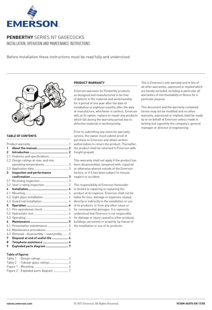
heads (keys 5, 7 and 23), diaphragm (key 6) and
O-rings from the fracture disk (key 4) end of the
stem (key 10).
4. Slide the stem (key 10) out to gain access to the
O-ring (key 8) in its center recess.
5. Remove the special hex nut, lockwasher, plug
assembly, O-ring and special washer (keys 7, 8, 9,
16 and 17) from the plug end of the stem (key 10).
6. Inspect and replace parts as necessary.
7. Lubricate the recessed area of the stem (key 10)
with a suitable lubricant and then install the O-ring
(key 8) into the recessed area.
8. Install one special washer (key 7), O-ring (key 8),
plug assembly (key 9), lockwasher (key 16) and
special hex nut (key 17) onto the appropriate end
of the stem (key 10) as shown in Figure 6. Insert
the plug and stem assembly into the body (key 1).
9. Install the following over the fracture disk end of
the stem:
• The lower diaphragm head (key 23) with its
chamfered side facing away from the plug
assembly, followed by an O-ring (key 8);
• The diaphragm, followed by another O-ring
(key 8);
• The diaphragm head (key 5) with its chamfered
side facing toward the plug assembly;
• The other special washer (key 7);
• The other hex nut (key 12). Good assembly
practice includes tightening both hex nuts
(keys 12 and 17) to 6 to 8 ft-lbs / 8 to
11 N•m torque.
10. Apply a suitable thread sealant to the threads of
the pipe plug (key 13), and install the pipe plug
into the body (key 1).
11. Install the upper casing (key 2) so that the vent
assembly (key 22, not shown) is pointed down or
otherwise protected.
12. Install the cap screws (key 11). Before tightening
them, make sure that the plug assembly (key 9)
is closed in order to provide enough slack in
the diaphragm.
13. Tighten the cap screws (key 11) using a crisscross
bolting pattern. Good assembly practice includes
tightening the cap screws to 13 to 17 ft-lbs / 18 to
23 N•m torque.
Parts List
Key Description Part Number
Repair Kits (included are keys 4, 6, 8,
9 and 21)
With red fracture disk R634X000012
With yellow fracture disk R634X000022
With white fracture disk R634X000032
1 WCC Steel Body
3/4 NPT
Type 634 39A1091X022
Type 634M 39A0584X022
1 NPT
Type 634 39A1090X032
Type 634M 39A0585X022
2 Upper Casing
Cast iron 29A0776X012
3* Disk Retainer
Steel 19A1935X022
4* Fracture Disk, Cast iron
Red color code 29A1936X012
Yellow color code 29A1936X022
White color code 29A1936X032
5 Diaphragm Head
Plated steel 19A1937X012
6* Diaphragm
Neoprene (CR) and Nylon (PA) fabric 19A1938X012
7 Special Washer
Plated steel (2 required) 19A1940X012
8* O-ring, Nitrile (NBR) (4 required) 1D6875X0022
9* Plug Assembly
Aluminum and Nitrile (NBR) 19A1943X012
10 Stem, Stainless steel 19A1941X012
11 Cap Screw, Plated steel (8 required) 1B787724052
12 Hex Nut, Steel 1A345724122
13 Pipe Plug, Plated steel 1A794728992
14 Snap Ring 12B9220X012
15 Pipe Plug, Plated steel (2 required
with standard construction or 1 required
with Tank Valve Inlet only) 1A500828992
15 Tank Valve (not shown), Plated steel
(1 required with Tank Valve Inlet only
or 2 required with standard construction 19A1951X012
16 Lockwasher, Plated carbon steel 1C225628982
17 Special Hex Nut, Stainless steel 19A1944X012
21* O-ring, Nitrile (NBR) 10A8931X012
22 Type Y602-12 Vent Assembly (not shown)
Plastic 27A5516X012
23 Lower Diaphragm Head
Plated steel 19A6901X012
*Recommended spare part.
14. Make sure that the disk retainer (key 3) and
attached parts are installed into the upper casing
according to steps 3 through 5 of the replacing
fracture disk procedure.
Parts Ordering
When corresponding with a local Sales Ofce about
Types 634 and 634M shutoff valves, include the type
number and all other pertinent information stamped
on the disk retainer and casing. Specify the eleven-
character part number when ordering from the
following Parts List.
6
Types 634 and 634M
