manuals.online logo
Brands
  1. Home
  2. •
  3. Brands
  4. •
  5. Emerson
  6. •
  7. Garbage Disposal
  8. •
  9. Emerson InSinkErator Grind2Energy User manual

Emerson InSinkErator Grind2Energy User manual

Organics Recycling System
Service Manual
Introduction
The InSinkErator®Grind2Energy™Organics
Recycling System is a non-sewer waste handling
system that processes food waste through a
specially designed Grind2Energy grinder.
The food waste is ground, then transferred to
an on-site holding tank where it is stored until
ready for pickup from a liquid waste hauler
for transport to an anaerobic digester where
it is converted into renewable energy such as:
electricity, heat, or Compressed Natural Gas
(CNG).
This Service Manual is intended for Authorized
Serve Agents of Grind2Energy and its
Technicians only. The intention of this manual is
to give the service Tech the ability to diagnose
the Grind2Energy Organics Recycling System
for any problems our customers encounter.
The process G2E will use is to replace larger
components of the system (i.e. Grinder, Pump,
and Controller) as whole components. But in
cases where the small component can be
replaced with less time, then those components
will be provided for those replacements. Our
intent is to recover from a down system, and
back to a fully operational system with one
service call. This philosophy is called One-and-
Done, and provides the customer with peace
of mind that they are supported by the highest
quality service network possible, offering as little
system operational down time as is necessary.
grind2energy.com Grind2Energy Technical Support: 844-874-7529 | a
G2E015-15F-89-84
Notes
grind2energy.com Grind2Energy Technical Support: 844-874-7529 | b
G2E015-15F-89-84
General Information
Prior to Service Call
• Make sure the customer has tried resetting the overload
protector and has checked for foreign objects jammed in the
grind chamber (see
Troubleshooting
on page 16).
• Before troubleshooting for mechanical problems, determine
if the problem is electrical:
- To determine if the problem is in the switch or the
grinder, bypass all electrical starting and/or electrical
controls and run the grinder direct.
- Make sure the grinder electrical specifications match the
electric power supply.
- Make sure the motor lead connections are correct for
the corresponding power supply and starting controls.
- Determine if there are electrical problems with other
appliances. This may indicate a problem in the building’s
electrical circuitry.
- Determine that the rotary shredder is rotating in the
direction marked on it by arrows.
After Completing Service
• Test the grinder for proper operation.
• Ensure that the Grind2Energy system is operational per
Manufacturer Specification.
• Ensure that all fittings are secure and do not leak.
grind2energy.com Grind2Energy Technical Support: 844-874-7529 | 1
G2E015-15F-89-84
Electrical Requirements
WARNING
ELECTRICAL SHOCK!
The grinder must be
permanently grounded.
The electrical wiring on grinders shipped from the factory are
not connected for a specific voltage. Refer to the Standard
Motor Connection Wiring Diagram attached to the inside of the
grinder terminal box cover for the correct voltage connections.
GRIND2ENERGY SYSTEM VOLTAGES ARE:
• 208-230/460 Volts for 3-phase electrical power.
NOTE:
• All amp ratings denote amp draw during a grind load.
• The grinder motor phase and voltage must be the
same as the line or power supply.
STANDARD MOTOR CONNECTION
DIAGRAM LOCATED UNDER
TERMINAL BOX COVER
Grind2Energy™System
Important Safety Instructions
REFER TO OPERATOR’S MANUAL
BEFORE OPERATING THE SYSTEM
These installation instructions are for the benefit of
the installing contractor.
For technical information not covered in this manual
please contact Grind2Energy at 1-844-874-7529.
DO NOT USE THE TABLE TOP AS A
WORKBENCH AS ITEMS MAY FALL
INTO THE GRINDER OPENING AND
DAMAGE THE SYSTEM
DO NOT STAND ON
PROCESSING TABLE
PUMP WEIGHS OVER 600 LBS.
UTILIZE PROPER EQUIPMENT TO
PLACE PUMP INTO POSITION
Understanding safety symbols in this guide
Important Safety Instructions
WARNING WARNING
CAUTION CAUTION
indicates a hazardous situation
which, if not avoided, could result
in death or serious injury.
WARNING
indicates a hazardous situation
which, if not avoided, could result in
minor or moderate injury.
CAUTION
used to address practices not
related to physical injury.
NOTICE
indicates specific safety-
related instructions or
procedures.
SAFETY INSTRUCTIONS
grind2energy.com Grind2Energy Technical Support: 844-874-7529 | 2
G2E015-15F-89-84
Tools Needed for
Service
Digital volt meter
Phillips and flathead
screwdrivers
Wire strippers
Adjustable wrench
Large pipe wrench
5/8" Hex key
Socket wrenches up to 1"
11 mm open end wrench
Thread sealing tape
Torque wrench
Strap wrench
(5-1/2" diameter min.)
5 gallon bucket
System
Components
Information on this page
and subsequent pages show
the system dimensions and
system components. It also
calls out the required service
test equipment and tools
you will need to perform
proper maintenance on the
Grind2Energy system.
Tools & Materials,
Installation Requirements
36" MIN. CLEARANCE BETWEEN TABLE AND
WALL OR OTHER OBJECTS
Top View
Front View
START
FULL
STOP
TANK START STOP
WARNING
ELECTRICALSHOCKHAZARD. DISCONNECTINCOMING POWER BEFORE
SERVICINGCONTROLCENTER. FAILURETO DO SO COULDRESULT IN
DEATHORSERIOUS PERSONAL INJURY. DOOR INTERLOCK SWITCHED
DISCONNECTCONTROLCIRCUIT ONLY.
68–1/4" (174 cm)
MINIMUM
36"
(91.5 cm)
30"
(77 cm)
GRINDING 208-230V/35A
SYSTEM*460V/20A
COLD WATER*
WATER WITHIN
12" TO TABLE
grind2energy.com Grind2Energy Technical Support: 844-874-7529 | 3
G2E015-15F-89-84
System Includes
Table & Components
System Table Includes
1
Table
2
Control
3
Grinder
4
Solenoid valves (2)
5
Siphon breaker
(backflow preventer)
Flow control (1gpm)
Flow control (5gpm)
7
Water shut-off valve
8
Hose
9
Spray nozzle
10
Squeegee
11
Splash Guard
12
Pump
13
Bin rake
14
Plumbing kit connection:
2" 90° schedule 80 PVC sweeps and
flanged schedule 80 PVC piping
(per install sheet, not shown)
15
Safety Glasses
Connections
WWater Inlet 1/2" copper stub
S2" PVC flange
EElectrical
Back View
Front View
6B
6A
9
START
FULL
STOP
TANK START STOP
WARNING
ELECTRICALSHOCK HAZARD. DISCONNECTINCOMING POWER BEFORE
SERVICINGCONTROL CENTER. FAILURETO DO SO COULD RESULTIN
DEATHOR SERIOUS PERSONAL INJURY. DOOR INTERLOCK SWITCHED
DISCONNECTCONTROL CIRCUITONLY.
3
W
S
2
1
E
4
6A
13
12
5
7
8
6B
7
grind2energy.com Grind2Energy Technical Support: 844-874-7529 | 4
G2E015-15F-89-84
Pump Kit Includes
1
Gear oil (1.1 liters) (not shown)
2
7.5L Glycol Verderlube (for pump)
(not shown)
3
2" Flex hose
4
2" 90° quick disconnect fitting
5
2” Cast inlet flange
6
Fiber gasket (3)
7
5/8" x 3 Hex head bolt (12)
8
5/8" x 5 Hex head bolt (4)
9
5/8" Washer (20)
10
5/8" Nut (16)
11
Pressure switch
12
2" PVC flange (3)
13
Rubber expansion joint
14
Limit control rod (2)
15
3/8" x 1-1/4" Hex head bolt (4)
16
3/8" Split washer (4)
17
3/8" Nylock nut (4)
18
Pump
19
2" ball valve
Pump Discharge Kit
System Includes
Pump & Components
3
4
7
19
6
6
12
18
14 13
15
17
16
11
6
8
5
9
10
grind2energy.com Grind2Energy Technical Support: 844-874-7529 | 5
G2E015-15F-89-84
Tank Kit Includes
1
Wireless tank sensor
2
Screws for wireless sensor (2)
NOTE: Metric-threaded screws
3
4" Check valve assembly (2)
4
4" Carbon filter vent cap
5
Tank-full sensor assembly
6
Discharge Kit
7
Discharge support
bracket assembly
8
Padlock
TANKS PLACED OUTSIDE
WILL ALSO INCLUDE:
9
Heat trace cable
10
Heating element cord
11
Thermostat
12
Discharge Jacket
System Includes
Tank & Components
1
2
3
5
4
11
9
10
8
6
7
12
grind2energy.com Grind2Energy Technical Support: 844-874-7529 | 6
G2E015-15F-89-84
System Wiring
TANK POWER REQUIREMENTS FOR OPTIONAL HEAT:
ATwo waterproof line-disconnect junction boxes, rated NEMA 4, within 6 feet of tank:
• Each to be rated 120V, with a 15 Amp, 30 mA GFCI breaker
Tools & Materials,
Installation Requirements
TANK HEAT
POWER
WEATHER-
PROOF
JUNCTION
BOXES:
PIPE HEAT
POWER
A
HEAT TRACE CABLE LIGHT CABLE
HEAT TRACE
CABLE
INSTALLED
ALONG
DISCHARGE
LINE AND
COMPLETELY
THROUGH
EXTERIOR
WALL.
3000 GAL. (11,356 L) shown
grind2energy.com Grind2Energy Technical Support: 844-874-7529 | 7
G2E015-15F-89-84
WARNING
SHOCK HAZARD! Turn off
electrical power at circuit breaker,
use voltmeter or circuit tester to
ensure that POWER IS OFF.
Wiring Connections
Incoming power supply requires that:
• Ground wire is securely fastened to
panel as shown.
• 208-230V system use #8 AWG wire
from line disconnect switch and control
box.
• 460V system use #12 AWG wire from
line disconnect switch to control box.
1
The pump lead wires are connected to
"T1, T2 & T3" as shown below.
2
The grinder lead wires are connected
to "M1, M2 & M3" as shown below.
3
The pressure switch leads are con-
nected to the control panel as shown
below (black to black, brown to brown,
blue to blue).
4
The lead wire for the tank float switch
is connected to terminal connections 2
and 15 as shown below. This wire runs
along the length of the discharge line
to the tank.
5
The 5gpm solenoid valve lead wires
are connected to terminal 11 & 12 as
shown below.
6
The 2gpm solenoid valve lead wires are
connected to terminal 7 & 10 as shown
below.
Grind2Energy™System
Wiring Connections
Adjust
Power Supply
INPUT
N N
DC ok
DC
ok
1 ON
0 OFF
2 2 2 4 4 4 7 10 11 12 15 M1 M2 M3 T1 T2 T3
L1 L2 L3
L1 L2 L3
GROUND
GROUND
GROUND
BLK
BRN
BLU
BLU
TANK FLUSH START STOP
WARNING
ELECTRICAL SHOCK HAZARD. DISCONNECT INCOMING POWER
BEFORE SERVICING CONTROL CENTER. FAILURE TO DO SO COULD
RESULT IN DEATH OR SERIOUS PERSONAL INJURY. DOOR
INTERLOCK SWITCHED DISCONNECT CONTROL CIRCUIT ONLY.
PRESS IF
JAMMED
Adjust
PowerSupply
INPUT
N
N
DCok
DC
ok
1 ON
0 OFF
2
2
2
4
4
4
7
10
11
12
15
M1
M2
M3
T1
T2
T3
L1
L2
L3
L1
L2
L3
GROUND
GROUND
GROUND
BLK
BRN
BLU
BLU
Control Box
17
INCOMING
POWER
PUMPGRINDER
FLOAT
SWITCH
2 GPM
SOLENOID
PRESSURE
SWITCH
5 GPM
SOLENOID
65 4 3 2 1
grind2energy.com Grind2Energy Technical Support: 844-874-7529 | 8
G2E015-15F-89-84
Complete Wiring Schematic
Grind2Energy™System
Wiring Connections
MODEL NO. GC-1, GC-2
208V, 230V, 460V 3PH 10HP
PART NO. 14789
INSINKERATOR DIVISION
EMERSON ELECTRIC CO.
4700 21ST STREET
RACINE, WI 53406-5093
L3
L2
L1
M3
M2
M1
H4H3
H2
H1
XF
X3
2
4
GROUND
0 OFF
-ON
L3
L2
L1
L3L2
L1
PANEL
GROUND
LUG
INCOMING
POWER
START
STOP
7
3
6
6
5
RUN
M
8
A2
4
A2
A1
3
3
5
7
7
8
EF
FV SS SW
PD
L1
L2
4
10
10
10
7
7
12 11
14 13
REV
FULL
13
14
15
12
M2
T3
11 M1
10
15
T2
7
T1
M3
44
4
M2
M3
M1
DISPOSER
MOTOR
24V WATER
SOLENOID
5 GPM
24V WATER
SOLENOID
2 GPM
PUMP
LEVEL SENSOR
4
16
16
2
2
17
17
4
712
1110 15
444
4
7
A2
A1
A2
M3
M2
M1
C
L3
L2
L1
4
PROPERTY DAMAGE
- ENSURE THAT THE CONTROL CENTER VOLTAGE AND PHASE MATCH THE
DISPOSER MOTOR AND ELECTRICAL SUPPLY. CHECK NAMEPLATES ON
DISPOSERS AND CONTROL CENTERS FOR VOLTAGE AND PHASE
SPECIFICATION.
- THE DISPOSER MOTOR WIRING CONNECTION IS SHOWN IN THE
DISPOSER TERMINAL BOX
- A PROPERLY FUSED DISCONNECT MUST BE INSTALLED ATTHE
ELECTRICAL SUPPLY SOURCE FOR THE CONTROL CENTER
- ALL CONTROL CENTERS AND DISPOSERS MUST BE CAREFULLY
AND PERMANETLY GROUNDED
- INSTALLATION MUST CONFORM TO LOCAL ELECTRICAL CODES.
ELECTRICAL SHOCK
- TURN OFF ALL ELECTRICAL SUPPLY TO THE DISPOSER BEFORE
ATTEMPTING ANY WORK ON IT. USE A VOLTMETER OR CIRCUT
TESTER TO ENSURE THAT POWER IS OFF.
GG
G
JUMPER
18
A1 15
16
A1 15
A
T
D
22
22
BR
BK BL
++ -- DC
NG L
11
12
A2
A1
BL
3
L1
T1
T2
L2
T3
L3
NO
NO
T1 T2 T3
95 96 97 98
A1
A2
Timed Off Dsp Delay
FUSE FUSE
X2 X1
2
2
PRESSURE SWITCH
A2
B1
18 16 A2
B1
22
4
A7
10
10
2
2
2
4
F
F
C
C
7
10
A
L
L
LL
G
G
NP
PN
B
B
E
24
A
M
TABLE
208
230
460
0
grind2energy.com Grind2Energy Technical Support: 844-874-7529 | 9
G2E015-15F-89-84
Control panel component identification
Grind2Energy™System
Wiring Connections
PUSHBUTTON
STOP
(N.C. RED)
PUSHBUTTON
START
(N.O. BLACK)
PUSHBUTTON
FLUSH
(N.O. YELLOW)
REMOTE
SENSOR
LIGHT (FULL)
DOOR
DISCONNECT
NON-METALLIC
ENCLOSURE
grind2energy.com Grind2Energy Technical Support: 844-874-7529 | 10
G2E015-15F-89-84
Control panel component identification
Grind2Energy™System
Wiring Connections
GROUND LUG
REVERSING
CONTACTOR
TANK FULL
RELAY
FORWARD
CONTACTOR
TIMED OFF
RELAY
CONTACTOR
INTERLOCK
DISPOSER
DELAY TIME
RELAY
TRANSFORMER
24V FUSE
PUMP
OVERLOAD
120V FUSE
PUMP
CONTACTOR
PRESSURE
RELAY
DC SUPPLY
FOR
PRESSURE
SWITCH
DOOR
DISCONNECT
REVERSE
PUSHBUTTON
CIRCUIT
BOARD
grind2energy.com Grind2Energy Technical Support: 844-874-7529 | 11
G2E015-15F-89-84
Grinder Replacement
Removing Grinder
DANGER SHOCK HAZARD!
Turn off electrical
power at circuit breaker, use voltmeter
or circuit tester to ensure that
POWER IS OFF.
1. Turn off electrical supply and water
supply to grinder.
2. Disconnect cold water connection from
grinder body.
3. Disconnect waste line from grinder.
4. Remove terminal box.
5. Remove trim band.
6. Mark to identify all motor leads wires
and electrical supply wires, then discon-
nect wires, grounding wire and conduit
from grinder.
7. Remove the 6 mounting screws used to
secure the grinder to the table.
8. Loosen the two lower jam nuts used to
secure leg position.
9. Use channel lock or similar to lower
grinder from mounting gasket.
10. Once free, slide grinder off table.
step 2
step 4
step 6
step 3
step 5
step 7
step 9step 10
step 8
grind2energy.com Grind2Energy Technical Support: 844-874-7529 | 12
G2E015-15F-89-84
Grinder Replacement
Installing Grinder
DANGER SHOCK HAZARD!
Turn off electrical
power at circuit breaker, use voltmeter
or circuit tester to ensure that
POWER IS OFF.
1. Place mounting flange up over existing
collar adaptor connection lip.
2. Push mounting flange up and out-of-
the-way, and fit the mounting gasket
onto the sink bowl connection lip.
3. Move mounting flange down over the
mounting gasket. Be certain that the
threaded fasteners in the mounting
flange fit in the recesses in the top of
the mounting gasket.
4. Position the grinder under the
mounting gasket.
5. Turn legs with channel-lock pliers to
rise the grinder so that it aligns with
the holes in the mounting gasket.
6. Install the six screws through the
grinder body flange and into the
mounting flange and secure.
7. Adjust legs so that the unit is sup-
ported evenly. Push o-ring on each leg
upwards, flush with bottom of cover.
(Refer to step 5 image.)
8. Secure legs in position by adjusting the
lower two jam nuts into place against
the adjustable portion of the leg and
each other.
9. Lock jam nuts in place by turning the
lower nut clockwise and rotating the
secondary nut counterclockwise until
snug, locking nuts against each other
repeat process for all three legs.
step 2
step 4
step 6
step 1
step 3
step 5
step 9step 8
grind2energy.com Grind2Energy Technical Support: 844-874-7529 | 13
G2E015-15F-89-84
Grinder Replacement
10. Wrap new trim band onto unit and
secure with two screws.
11. Re-install conduit.
12. Connect electrical supply wires to the
motor leads. Reference the wiring
diagram attached to the inside of the
terminal box of the Wiring Diagrams
section of the Grinder Control Center
installation manual.
13. Reinstall terminal box.
Connecting Grinder
DANGER SHOCK HAZARD!
Turn off electrical
power at circuit breaker, use voltmeter
or circuit tester to ensure that
POWER IS OFF.
14. Connect waste line to grinder.
15. Connect cold water supply to
grinder body water inlet (if previously
installed).
16. Turn on electrical and water supplies.
17. Test the grinder to ensure the cutting
elements rotate counter-clockwise
and the water flows automatically.
Make sure the grinder is securely
mounted and does not leak from
the connections.
18. Ensure that the rotary shredder is
rotating in the direction marked on it
by arrows.
step 11
step 13
step 15
step 18
step 10
step 12
step 14
grind2energy.com Grind2Energy Technical Support: 844-874-7529 | 14
G2E015-15F-89-84
Terminal Box
Overload
Protector
Mounting
Bracket
Grounding
Screw
Screw
Screw
Overload Protector
Terminal
6 1
25
4 3
Center post (3 Ø shown)
Overload Protector
Testing Overload Protector
WARNING SHOCK HAZARD!
Turn off electrical power at circuit
breaker, use voltmeter or circuit tester to ensure that
POWER IS OFF.
1. Remove screw and terminal box (figure 23).
2. Remove two screws, securing overload protector to
bracket and pull out from unit. Disconnect overload wires
from stator.
3. Push red button in and check continuity between all
terminals and center post using an ohmmeter (figure 24).
6 terminals – 3 Ø
4. Check for continuity between all terminals and center
post. Replace overload protector if circuit is open on any
terminal/center post combination.
5. Re-install terminal box in reverse order.
Replacing Overload Protector
1. Remove screw and terminal box (figure 24).
2. Disconnect wires.
3. Remove two screws securing overload protector to
bracket, disconnect wires and remove protector.
4. Connect new switch wires and tuck wires into bracket
and secure new protector to bracket using two screws.
5. Re-install terminal box and screw.
grind2energy.com Grind2Energy Technical Support: 844-874-7529 | 15
G2E015-15F-89-84
figure 24. Testing Overload Protector
figure 23. Terminal Box and Components
figure 24. Testing Overload Protector
Troubleshooting
Troubleshooting Guide
PROBLEM POSSIBLE CAUSE SOLUTION
Grinder and pump
do not operate
No power to control panel Verify that power is at control panel. Turn on power to control panel.
Control panel faulty Replace control panel.
Grinder will not
operate but water
and pump function
properly
Overload protector tripped
on grinder
Push the grinder overload protector reset button, this may require a 5
minute wait for it to cool down so that it can be reset.
Grinder is jammed Remove jam.
Overload protector is
burnt out
Test overload protector (see figure 24), if defective replace overload
protector (see overload protector page 15).
Grinder motor
hums but does not
run while pump
and water function
properly
Jammed rotating shredder Remove jam
Improper voltage to grinder Verify that supply voltage and phase match information on control panel.
If they do not match bring in correct voltage and phase to machine.
Grinder motor is not wired
correctly
Verify connections (see standard motor connection diagram located under
terminal box cover).
Lower end frame and upper
end bell misaligned (thru
bolts loose, bent or broken)
Replace grinder (see grinder replacement page 12).
WARNING SHOCK HAZARD!
Turn off electrical power at
circuit breaker, use voltmeter or circuit tester to
ensure that POWER IS OFF.
If the problem looks to be electrical:
• To determine if the problem is in the controller, pump
or the grinder, bypass all electrical starting and/or
electrical controls and run the pump & grinder direct.
• Make sure the grinder & pump electrical specifications
match the electric power supply.
• Make sure the motor lead connections are correct for
the corresponding power supply and starting controls.
• Determine if there are electrical problems with other
kitchen appliances. This may indicate a problem in the
building’s electrical circuitry.
Controls
Pressure switch
display
Jam reset
Grinder
overload
relay
grind2energy.com Grind2Energy Technical Support: 844-874-7529 | 16
G2E015-15F-89-84
Troubleshooting
PROBLEM POSSIBLE CAUSE SOLUTION
Grinder runs
briefly then trips
overload
Jammed rotating shredder Remove jam.
Improper voltage to grinder Verify that supply voltage and phase match information on control panel.
If they do not match bring in correct voltage and phase to machine.
Grinder motor is not wired
correctly
Verify connections (see standard motor connection diagram located
under terminal box cover).
Electrical supply overloaded Connect system to dedicated electrical supply.
Grinder runs slow
and/or stops
when food waste
is inserted
Improper voltage to grinder Verify that supply voltage and phase match information on control panel.
If they do not match bring in correct voltage and phase to machine.
Loose mounting screws Tighten screws up.
Pinched or broken mounting
gasket
Replace gasket.
Grinder overload
protector trips
or fuse/circuit
breaker blows
immediately after
starting grinder
Improper fuse or circuit breaker
used
Check fuse or circuit breaker to verify that it matches required
specifications.
Improper voltage to grinder Verify that supply voltage and phase match information on control panel.
If they do not match bring in correct voltage and phase to machine.
Control panel wired incorrectly Verify connections (see standard motor connection diagram located
under terminal box cover).
Short in stator Replace grinder.
Water leaking
from bottom of
grinder
Bearing seal failure With system off, dry floor and bottom of grinder then add water until it is
above shredder plate, if water leaks on to floor; replace grinder.
Upper end bell cracked or
eroded away
With system off, dry floor and bottom of grinder then add water until it is
above shredder plate if water leaks onto floor; replace grinder.
Water sprayed into grinder
housing during clean up
With system off, dry floor and bottom of grinder then add water until it
is above the shredder plate, if water leaks onto floor replace grinder, if
water does not leak instruct end user not to spray grinder with water.
Grinder squeals
during operation
Bearing are worn Replace grinder.
Rotor core is loose on shaft Replace grinder.
Grinder vibrates
excessively
Too much water in grinder Slow down feeding of liquids.
Grinder is overloaded with non-
biodegrable materials
Turn off grinder main power on control box and clear waste.
Water/slurry
leaking from
grinder waste
discharge or
mounting
Loose mounting screws Tighten up screws.
Pinched or broken mounting
gasket
Replace gasket.
grind2energy.com Grind2Energy Technical Support: 844-874-7529 | 17
G2E015-15F-89-84
Troubleshooting
PROBLEM POSSIBLE CAUSE SOLUTION
Ground waste
is not passing
through grinder
Improper wire connections Verify that grinder’s rotating shredder is going counter-clockwise, if
incorrect swap wire connections.
Water or slurry
leaks from grind
chamber area
Stationary shedder gasket is
faulty
Replace grinder.
Water leaks from
siphon breaker
Loose plumbing connections Tighten plumbing connections.
Grinder does not
grind food waste
Improper wire connections Do not turn off system until all food waste has been ground.
Grind elements are worn With power off, verify edge of rotating shredder, if excessively rounded
replace grinder.
grind2energy.com Grind2Energy Technical Support: 844-874-7529 | 18
G2E015-15F-89-84

This manual suits for next models

3

Other Emerson Garbage Disposal manuals
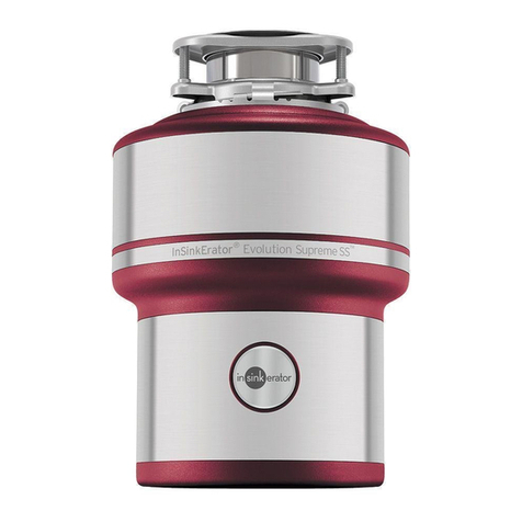
Emerson InSinkErator 55 User manual

Emerson

Emerson InSinkErator 55 User manual

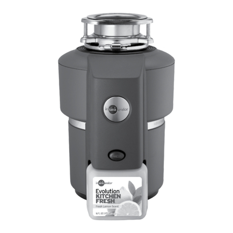
Emerson InSinkErator EVOLUTION SELECT PLUS User manual

Emerson

Emerson InSinkErator EVOLUTION SELECT PLUS User manual

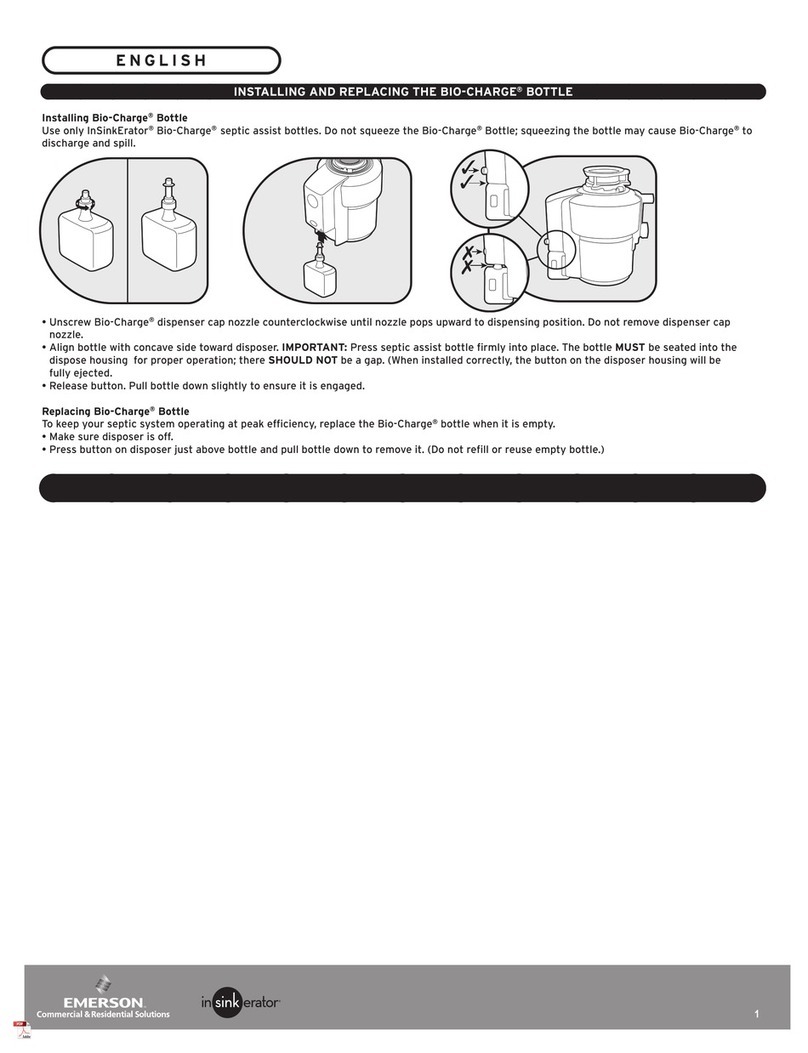
Emerson In Sink Erator BIO-CHARGE Instruction Manual

Emerson

Emerson In Sink Erator BIO-CHARGE Instruction Manual

Emerson InSinkErator EVOLUTION PRO 750 User manual

Emerson

Emerson InSinkErator EVOLUTION PRO 750 User manual

Emerson InSinkErator Evolution PRO Series User manual

Emerson

Emerson InSinkErator Evolution PRO Series User manual

Emerson InSinkErator EVOLUTION PRO 880LT User manual

Emerson

Emerson InSinkErator EVOLUTION PRO 880LT User manual

Emerson InSinkErator WasteXpress WX-500-7-WX101 User manual

Emerson

Emerson InSinkErator WasteXpress WX-500-7-WX101 User manual

Emerson InSinkErator Evolution Series User manual

Emerson

Emerson InSinkErator Evolution Series User manual

Emerson InSinkErator 777SS User manual

Emerson

Emerson InSinkErator 777SS User manual

Emerson EVOLUTION ESSENTIAL 79361K-ISE User manual

Emerson

Emerson EVOLUTION ESSENTIAL 79361K-ISE User manual

Popular Garbage Disposal manuals by other brands
Bort MASTER ECO manual

Bort

Bort MASTER ECO manual

Waste King WLC-100 owner's guide

Waste King

Waste King WLC-100 owner's guide

disperator 500A-GTS-E65 EXCELLENT SERIES user manual

disperator

disperator 500A-GTS-E65 EXCELLENT SERIES user manual

InSinkErator AQUASAVER AS-101K installation manual

InSinkErator

InSinkErator AQUASAVER AS-101K installation manual

Teral DSP-125H-AWS manual

Teral

Teral DSP-125H-AWS manual

Kraus KWD100-75 installation manual

Kraus

Kraus KWD100-75 installation manual

DAYRON 26204 quick start guide

DAYRON

DAYRON 26204 quick start guide

Teka TR 750 Installation, care & use manual

Teka

Teka TR 750 Installation, care & use manual

DELTA-SPORT 313455 Instructions for use

DELTA-SPORT

DELTA-SPORT 313455 Instructions for use

Ninestars DZT-12-5 user manual

Ninestars

Ninestars DZT-12-5 user manual

Husqvarna LX 95 Operator's manual

Husqvarna

Husqvarna LX 95 Operator's manual

GE Disposall GFB1050V Use and care

GE

GE Disposall GFB1050V Use and care

MULTIQUIP Mikasa Series MVH306ds2 Operation and parts manual

MULTIQUIP

MULTIQUIP Mikasa Series MVH306ds2 Operation and parts manual

CRAM-A-LOT SCR-T1 Operator's instruction manual

CRAM-A-LOT

CRAM-A-LOT SCR-T1 Operator's instruction manual

Elephants Foot eDiverter Photo step by step instruction booklet
Elephants Foot

Elephants Foot eDiverter Photo step by step instruction booklet
KitchenAid KCDS075T manual

KitchenAid

KitchenAid KCDS075T manual

MULTIQUIP Mikasa Series Operation manual

MULTIQUIP

MULTIQUIP Mikasa Series Operation manual

AGT AGENT TRADE CRBH 130 user manual

AGT

AGT AGENT TRADE CRBH 130 user manual

manuals.online logo
manuals.online logoBrands
  • About & Mission
  • Contact us
  • Privacy Policy
  • Terms and Conditions

Copyright 2025 Manuals.Online. All Rights Reserved.