Emerson i2P-100 User manual

www.Fisher.com
D103198X012
Type i2P-100 Electro-Pneumatic Transducers
Contents
Introduction 1. . . . . . . . . . . . . . . . . . . . . . . . . . . . . . .
Scope of Manual 1. . . . . . . . . . . . . . . . . . . . . . . . . . .
Description 1. . . . . . . . . . . . . . . . . . . . . . . . . . . . . . . .
Specifications 3. . . . . . . . . . . . . . . . . . . . . . . . . . . . .
Educational Services 4. . . . . . . . . . . . . . . . . . . . . . .
Installation 4. . . . . . . . . . . . . . . . . . . . . . . . . . . . . . . .
Mounting 5. . . . . . . . . . . . . . . . . . . . . . . . . . . . . . . .
Pneumatic Connections 6. . . . . . . . . . . . . . . . . . . .
Supply Pressure Requirements 6. . . . . . . . . . . .
Diagnostic Connections 7. . . . . . . . . . . . . . . . . . .
Vent 8. . . . . . . . . . . . . . . . . . . . . . . . . . . . . . . . . . .
Electrical Connections 8. . . . . . . . . . . . . . . . . . . . .
Operating Information 8. . . . . . . . . . . . . . . . . . . . . . .
Calibration 8. . . . . . . . . . . . . . . . . . . . . . . . . . . . . . .
Equipment Required 9. . . . . . . . . . . . . . . . . . . . .
Calibration Procedure 9. . . . . . . . . . . . . . . . . . . .
Principle of Operation 10. . . . . . . . . . . . . . . . . . . . . .
Maintenance 10. . . . . . . . . . . . . . . . . . . . . . . . . . . . .
Troubleshooting 11. . . . . . . . . . . . . . . . . . . . . . . . .
Converter Module Replacement 11. . . . . . . . . . . .
Electronics Module Replacement 11. . . . . . . . . . .
Relay Maintenance 12. . . . . . . . . . . . . . . . . . . . . . .
Parts Ordering 13. . . . . . . . . . . . . . . . . . . . . . . . . . . .
Parts List 13. . . . . . . . . . . . . . . . . . . . . . . . . . . . . . . .
Introduction
Scope of Manual
This instruction manual provides installation,
operation, maintenance, and parts ordering
information for the Type i2P-100 transducer (see
figure 1). Refer to separate manuals for instructions
covering equipment used with the transducer.
No person may install, operate or maintain a Type
i2P-100 electro-pneumatic transducer without
first Dbeing fully trained and qualified in valve,
actuator and accessory installation, operation and
maintenance, and Dcarefully reading and
understanding the contents of this manual. If you
have any questions about these instructions, contact
your Fisher sales office.
W8710
REPLACEABLE
FILTER WITH
REMOVABLE
ORIFICE
INTEGRAL
PNEUMATIC
RELAY
VENT
Figure 1. Type i2P-100 Electro-Pneumatic Transducer
Description
The transducer, shown in figure 3, receives a 4 to 20
milliampere dc input signal and transmits a
proportional user field-configurable pneumatic output
pressure to a final control element. The pneumatic
output ranges are typically 0.2 to 1.0 bar (3 to 15
psig) and 0.4 to 2.0 bar (6 to 30 psig). A typical
application is in electronic control loops where the
final control element is a control valve assembly that
is pneumatically operated. The input signal and
output pressure range of the transducer is indicated
on the nameplate, attached to the housing.
CAUTION
Dropping or rough handling of the
transducer can cause damage to the
converter module resulting in a shifted
output or a minimum output.
Instruction Manual
Form 5777
September 2004 i2P-100 Transducer

i2P-100 Transducer
Instruction Manual
Form 5777
September 2004
2
Table 1. Specifications
Input Signal(1)
Available as standard with 4-20 mA.
User configurable by dip switch for split ranging,
see table below.
Output Signal(1)
Available as standard 0.2 to 1.0 bar (3 to 15 psig)
or 0.4 to 2.0 bar (6 to 30 psig). User configurable
by dip switch selection and zero and span
potentiometer adjustment, see table below.
INPUT SIGNAL
OUTPUT PRESSURE
INPUT SIGNAL BAR PSIG
4to20mAdc
0.2 to 1.0 3 to 15
4 to 20 mA dc 0.4 to 2.0 6 to 30
4 to 12 mA dc 0.2 to 1.0 3 to 15
12 to 20 mA dc 0.2 to 1.0 3 to 15
Equivalent Circuit
The Type i2P-100 equivalent circuit is a series
circuit consisting of a constant voltage drop
(battery) of approximately 4 V dc and a total
resistance of 40 ohms. Input is shunted by two
6.8 V zener diodes (see figure 9).
Supply Pressure(1,5)
Recommended: 0.3 bar (5 psi) higher than upper
range limit of output signal
Maximum: 3.4 bar (50 psig)
Medium: Air or Natural Gas(4)
Average Steady State Flow Rate(1)(2)
OUTPUT RANGE
0.2 to 1.0 bar (3-15 psig) 0.4 to 2.0 bar (6-30 psig)
SUPPLY PRESSURE
1.5 bar (20 psig) 2.4 bar (35 psig)
OUTPUT FLOW RATE OUTPUT FLOW RATE
Bar Psig Normal
m3/h Scfh Bar Psig Normal
m3/h Scfh
0.2 3 0.08 3.0 0.4 6 0.09 3.6
0.6 9 0.12 4.5 1.2 18 0.19 7.0
1.0 15 0.17 6.3 2.1 30 0.27 10.2
Maximum Output Air Capacity(2)
8.0 m3/hr (5.0 scfm) at 1.4 bar (20 psig) supply
pressure
Performance(3)
Reference Accuracy: ±1.0% of full scale output
span; includes combined effects of hysteresis,
linearity, and deadband
Independent Linearity(1):±0.75% of full scale
output span
Hysteresis(1):0.4% of full scale output span
Frequency Response(1):Gain is attenuated 3 dB
at 6 Hz with transducer output signal piped to a
typical instrument input
Temperature Effect: ±0.14% per degrees
Celsius (±0.75% per degrees Fahrenheit) of span
Supply Pressure Effect: 0.2% of full scale output
span per bar supply pressure change (0.2% of
full scale output span per psi supply pressure
change)
Vibration Effect: Less than 1% of full scale
output span when tested to SAMA PMC 31.1,
Condition 3
Electromagnetic Interference (EMI)(1):Tested
per IEC 61326-1 (Edition 1.1).Conforms to the
European EMC Directive. Meets emission levels
for Class A equipment (industrial locations) and
Class B equipment (domestic locations). Meets
immunity requirements for industrial locations
(Table A.1 in the IEC specification document).
Immunity performance shown in table 2.
Operating Ambient Temperature Limits(5)
-40 to 85_C (- 40 to +180_F)
Electrical Classification
Hazardous Area(6):
Explosion proof, Dust-Ignition proof, DIV 2,
Intrinsically Safe
Explosion proof, Non-incendive,
Dust-Ignition proof, Intrinsically Safe
Intrinsically Safe, Type n and Flameproof
Approved for use with natural gas(4)
(continued)
APPROVED
ATEX
(LCIE)
IECEx
(CSA)

i2P-100 Transducer
Instruction Manual
Form 5777
September 2004
3
Table 1. Specifications (continued)
Electrical Housing: NEMA 3R, CSA enclosure
Type 3R, IP66 per IEC60529
Connections
Supply and Output Pressure: 0.25 inch NPT
female connection
Vent: 0.25 inch NPT female
Electrical: JStandard 0.5 inch NPT
Wire Size: 18 to 22 AWG
Adjustments(7)
Zero and Span: Trim potentiometers (20 turn) for
zero and span adjustments are located under the
housing cap (see figure 10).
Switch: Allows input signal split range and
user-configurable 0.2 to 2 bar (3 to 30 psig)
output.
Mounting Position
JActuator Jpipestand or Jsurface
Approximate Weight (Transducer Only)
2.5 kg (5.5 lbs)
Actuator Stroking Time
See figure 2
1. These terms are defined in ISA Standard S51.1.
2. Normal m3/hr—Normal cubic meters per hour (0_C and 1.01325 bar, absolute). Scfh—Standard cubic feet per hour (60_F and 14.7 psia).
3. Performance values are obtained using a transducer with a 4 to 20 mA dc input signal and a 0.2 to 1.0 bar (3 to 15 psig) output signal at an ambient temperature of 24_C (75_F).
4. This product is approved for use with Natural Gas. Natural gas to contain no more than 20 ppm of hydrogen sulphide.
5. The pressure and temperature limits in this manual and any applicable standard or code limitation should not be exceeded.
6. Approvals are pending
7. For other ranges, zero and span adjustments are needed.
Table 2. Immunity Performance
Port Phenomenon Basic Standard Performance Criteria
Electrostatic discharge (ESD) IEC 61000-4-2 A
Enclosure Radiated EM field IEC 61000-4-3 A
Enclosure
Rated power frequency magnetic field IEC 61000-4-8 A
Burst (fast transients) IEC 61000-4-4 A
I/O signal/control Surge IEC 61000-4-5 A
I/O
signal/control
Conducted RF IEC 61000-4-6 A
Specification limit = ±1% of span
LOADING
EXHAUSTING
TIME (%)
0 102030405060708090100
0
10
20
30
40
50
60
70
80
90
100
OUTPUT
(% OF TYPE i2P-100 OUTPUT SPAN)
A6815 / IL
Figure 2. Output-Time Relationships for Type i2P-100
Transducer
Specifications
Specifications for the Type i2P-100 transducer are
listed in table 1.
WARNING
This product is intended for a specific
current range, temperature range and
other application specifications.
Applying different current, temperature
and other service conditions could
result in malfunction of the product,
property damage or personal injury.

i2P-100 Transducer
Instruction Manual
Form 5777
September 2004
4
W8723
CONDUIT
CONNECTION
FIELD
TERMINATION AND
ELECTRONICS
MODULE CAP
CONVERTER
MODULE CAP
Figure 3. Type i2P-100 Electro-Pneumatic Transducer
Mounted on a Size 30 667 Sliding-Stem Actuator
Educational Services
For information on available courses for the Type
i2P-100 Electro-Pneumatic Transducer, as well as a
variety of other products, contact:
Emerson Process Management
Educational Services, Registration
P.O. Box 190; 301 S. 1st Ave.
Marshalltown, IA 50158-2823
Phone: 800-338-8158 or
Phone: 641-754-3771
FAX: 641-754-3431
e-mail: [email protected]
Note
Fisher does not assume responsibility
for the selection, use and maintenance
of any product. Responsibility for the
selection, use and maintenance of any
Fisher product remains with the
purchaser and end-user.
W8693
CONDUIT
CONNECTION
FIELD
TERMINATION AND
ELECTRONICS
MODULE CAP
CONVERTER
MODULE CAP
Figure 4. Type i2P-100 Electro-Pneumatic Transducer
Mounted on a Size 33 1052 Rotary Actuator, 3610J Positioner
and V300B Rotary Valve.
Installation
The i2P-100 transducer has been designed and
approved for use with either air or natural gas as the
supply medium. In normal operation the unit will vent
the supply medium into the surrounding atmosphere
unless it is remotely vented. When using natural gas
as the supply medium in a non-hazardous location,
remote venting of the unit is required. Failure to do
so could result in personal injury, property damage,
and area re-classification. For hazardous locations
remote venting of the unit may be required,
depending upon the area classification, and as
specified by the requirements of local, regional, and
federal codes, rules and regulations. Failure to do so
when necessary could result in personal injury,
property damage, and area re-classification.
WARNING
To avoid personal injury or property
damage from the sudden release of
pressure:
DAlways wear protective clothing
and eyewear when performing any
installation operations.
DIf installing into an existing
application, also refer to the WARNING
at the beginning of the Maintenance
section of this instruction manual.
DCheck with your process or safety
engineer for any additional measures
that must be taken to protect against
process media.

i2P-100 Transducer
Instruction Manual
Form 5777
September 2004
5
58.7
(2.31)
22.3
(0.88)
75.2
(2.96)
55.7
(2.19)
33.3
(1.31)
67.8
(2.67)
75.7
(2.98)
22.9
(0.90)
33.3
(1.31)
33.3
(1.31)
0.25 18 NPT VENT
OR PIPE-A-WAY
CONNECTION 0.25 18 NPT
OUTPUT
CONNECTION
67 (2.62) CAP
REMOVAL
CLEARANCE
67 (2.62) CAP
REMOVAL
CLEARANCE
0.25 18 NPT
SUPPLY
CONNECTION
0.5 14 NPT
CONDUIT
CONNECTION
81.6
(3.21)
74.2
(2.92)
34.7
(1.37)
98.7
(3.89)
mm
(INCH)
GE0643
(sheet 1 of 4)
0.25 18 NPT
OUTPUT
CONNECTION
103.9
(4.09)
103.9
(4.09)
36.3
(1.43)
Figure 5. Dimensions and Connections
WARNING
This unit vents the supply medium into
the surrounding atmosphere. When
installing this unit in a non-hazardous
location with natural gas as the supply
medium, you must remotely vent this
unit to a safe location. Failure to do so
could result in personal injury or
property damage from fire or
explosion, and area re-classification.
When installing this unit in a
hazardous location remote venting of
the unit may be required, depending
upon the area classification, and as
specified by the requirements of local,
regional, and federal codes, rules and
regulations. Failure to do so when
necessary could result in personal
injury or property damage from fire or
explosion, and area re-classification.
Vent line piping should comply with
local and regional codes and should
be as short as possible with adequate
inside diameter and few bends to
reduce case pressure buildup.
Mounting
When a transducer is ordered as part of a control
valve assembly, the factory mounts the transducer
on the actuator and connects the necessary tubing,
then adjusts the transducer as specified on the
order. See figure 3 and 4 for typical mounting
configurations.
Transducers also can be ordered separately for
mounting on a control valve assembly already in
service, or for mounting on a 2-inch diameter
pipestand, or a flat surface. The transducer may be
ordered either with or without mounting parts.
Mounting parts include a mounting plate and bolts
and, if ordered for pipestand mounting, a pipe clamp.
Tubing is not included if the transducer is not factory
mounted. Use 0.375 inch diameter tubing for all
input and output connections. The length of tubing

i2P-100 Transducer
Instruction Manual
Form 5777
September 2004
6
MOUNTING
BRACKET
i2P-100 TRANSDUCER
REGULATOR
Figure 6. Typical Type i2P-100 Mounting With Type 67CFR Filter Regulator
between the transducer output and the final control
element should be as short as possible. Transducer
overall dimensions are shown in figure 5. If
weatherproofing is required, mount the transducer
so that the vent can drain. Do not allow moisture or
condensate to collect in the vent.
Note
The vent will not drain properly when
mounted in the downward position.
Pneumatic Connections
As shown in figure 5, all pressure connections on the
transducer are 0.25 inch NPT female connections.
Use 0.375 inch tubing for all pressure connections.
Refer to the vent subsection below for remote vent
connections.
Supply Pressure Requirements
WARNING
Severe personal injury or property
damage could result from an unstable
process if the instrument supply
medium is not clean, dry, oil-free and
non-corrosive. While use and regular
maintenance of a filter that removes
particles larger than 40 microns in
diameter will suffice in most
applications, check with a Fisher Field
office and Industry Instrument air
quality standards for use with
corrosive air or if you are unsure about
the proper amount or method of air
filtration or filter maintenance.
Supply pressure must be clean, dry air or
noncorrosive gas. Use a Fisher Type 67CFR Filter
Regulator, or equivalent, to filter and regulate supply
air. The filter regulator can be mounted on a bracket
with the transducer as shown in figure 6 or mounted
on the actuator mounting boss. An output pressure
gauge may be installed on the regulator to indicate

i2P-100 Transducer
Instruction Manual
Form 5777
September 2004
7
PIPE BUSHING
BODY PROTECTOR
BODY
PIPE TEE
PIPE NIPPLE
STEM
PROVIDED WHEN
GAUGE IS SPECIFIED
GAUGE
GE06439-A
(sheet 1 of 4)
B2395-1/IL
Figure 7. Diagnostics Hookup for Type i2P-100 Transducer
+
-
+
--+
1
CONTROL
DEVICE
TRANSDUCER
HOUSING
TERMINAL
BLOCK
FIELD WIRING
EARTH
GROUND
NOTE:
FOR TROUBLESHOOTING OR MONITORING OPERATION,
AN INDICATING DEVICE CAN BE A VOLTMETER ACROSS
A 250 OHM RESISTOR OR A CURRENT METER.
1
A3875/IL
Figure 8. Typical Field Wiring Diagram
the supply pressure to the transducer. Also, as an
aid for calibration, a second gauge may be installed
on the transducer to indicate transducer output
pressure.
Connect the nearest suitable supply source to the
0.25 inch NPT IN connection on the filter regulator (if
furnished) or to the 0.25 inch NPT SUPPLY
connection on the transducer case (if the filter
regulator is not attached).
Diagnostic Connections
To support diagnostic testing of
valve/actuator/positioner packages, special
connectors and hardware are available. Typical
connector installations are shown in figure 7. The
hardware used includes a 0.25 inch NPT pipe nipple
and pipe tee with a 0.125 inch NPT pipe bushing for
the connector. The connector consists of a 0.125
inch NPT body and body protector.
Note
If the Type i2P-100 transducer is used
in a valve assembly with a positioner,
no hook-up for diagnostic testing is
required for the Type i2P-100. The
hook-up for diagnostic testing should
be installed at the positioner.
Install the connectors and hardware between the
Type i2P-100 transducer and the actuator.
1. Before assembling the pipe nipple, pipe tee, pipe
bushings, actuator piping, and connector body, apply
sealant to all threads.
2. Turn the pipe tee to position the connector body
and body protector for easy access when doing
diagnostic testing.

i2P-100 Transducer
Instruction Manual
Form 5777
September 2004
8
Vent
WARNING
This unit vents the supply medium into
the surrounding atmosphere. When
installing this unit in a non-hazardous
location with natural gas as the supply
medium, you must remotely vent this
unit to a safe location. Failure to do so
could result in personal injury or
property damage from fire or
explosion, and area re-classification.
When installing this unit in a
hazardous location remote venting of
the unit may be required, depending
upon the area classification, and as
specified by the requirements of local,
regional, and federal codes, rules and
regulations. Failure to do so when
necessary could result in personal
injury or property damage from fire or
explosion, and area re-classification.
Vent line piping should comply with
local and regional codes and should
be as short as possible with adequate
inside diameter and few bends to
reduce case pressure buildup.
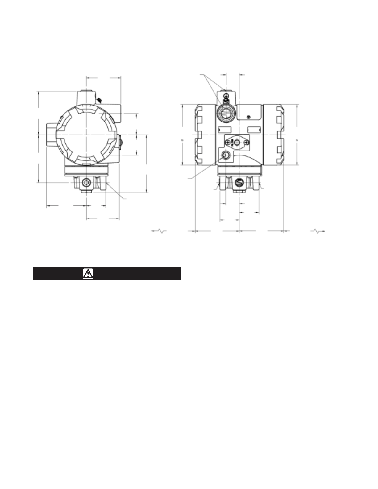
If a remote vent is required, the vent line must be as
short as possible with a minimum number of bends
and elbows. To connect a remote vent, remove the
plastic vent (key 71, figure 13). The vent connection
is 0.25 inch NPT female. Use 0.375 inch tubing to
provide a remote vent.
Electrical Connections
WARNING
For explosion-proof applications, or
when using natural gas as the supply
medium, disconnect power before
removing the housing cap. Personal
injury or property damage from fire or
explosion may result if power is not
disconnected before removing the cap.
For intrinsically safe installations, refer
to the nameplate or to instructions
provided by the barrier manufacturer,
for proper wiring and installation.
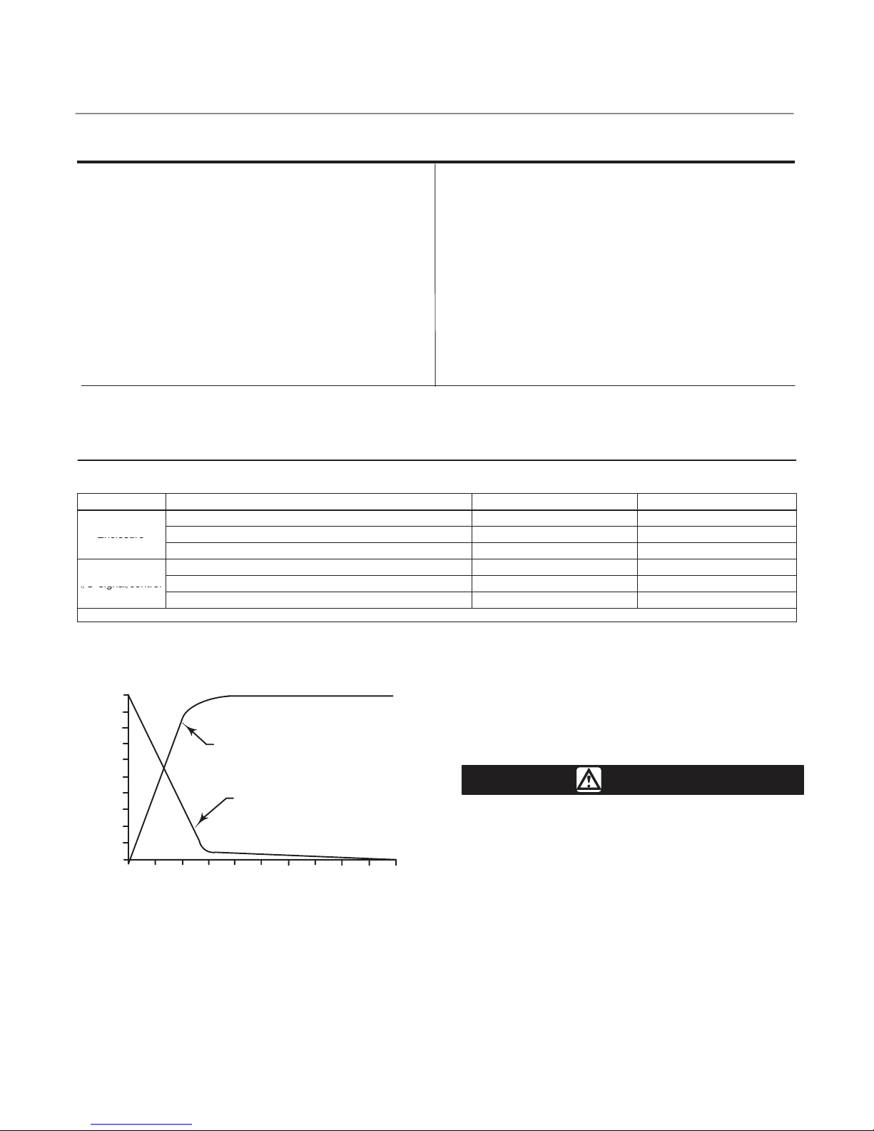
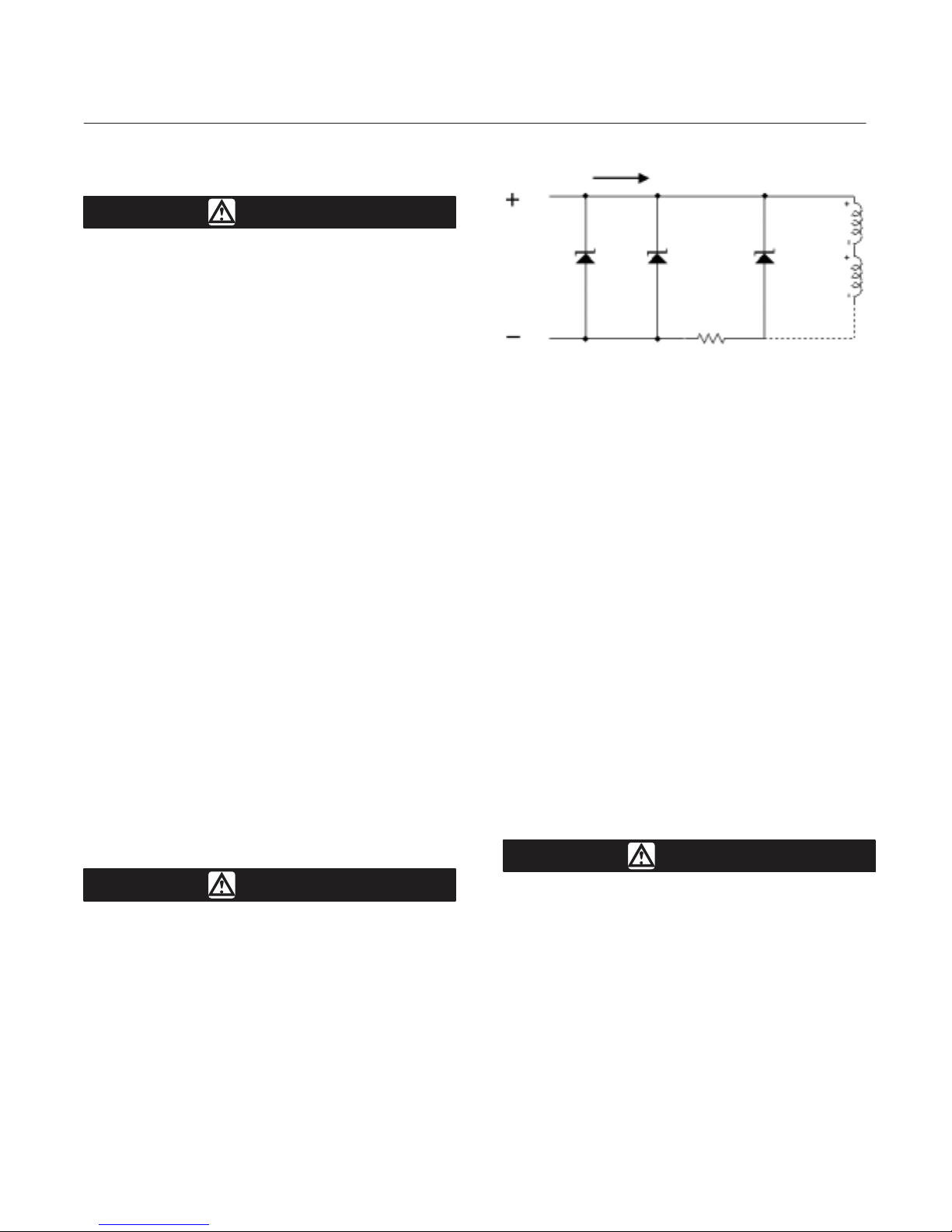
4 - 20 mA
6.8V 6.8V 4V
40 Ohm
Figure 9. Equivalent Circuit
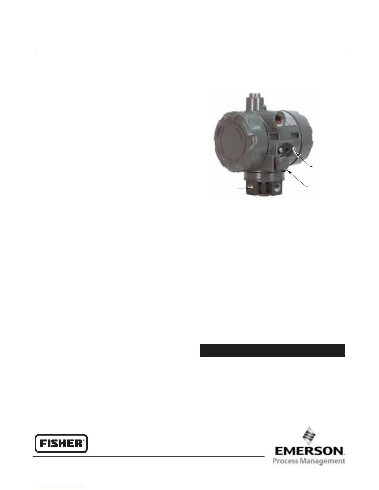
Use the 0.5 inch NPT conduit connection, shown in
figure 5, for installation of field wiring.
Refer to figures 8, 9, and 10 when connecting field
wiring from the control device to the transducer.
Connect the positive wire from the control device to
the transducer ‘‘+’’ terminal and, the negative wire
from the control device to the transducer ‘‘-’’
terminal. Do not overtighten the terminal screws.
Maximum torque is 0.45 NSm (4 lbfSin.). Connect the
transducer grounding terminal to earth ground.
Grounding terminals are provided both inside and
outside the transducer housing.
Operating Information
The normal mode of operation for Type i2P-100
transducer requires that the pneumatic output
pressure be piped to the final control element. If this
is not done the resulting pneumatic output will vent
to the atmosphere.
Calibration
WARNING
On explosion-proof instruments, or
when using natural gas as the supply
medium, remove electrical power
before removing either of the the
housing caps in a hazardous area.
Personal injury or property damage
may result from fire or explosion if
power is applied to the transducer with
the cap removed in a hazardous area.
For intrinsically safe areas, current
monitoring during operation must be
with a meter approved for use in
hazardous areas.

i2P-100 Transducer
Instruction Manual
Form 5777
September 2004
9
PCB/CUP
ASSEMBLY
SPAN
ADJUSTMENT
FIELD
WIRING
CONNECTION
SWITCH
SETTINGS(1,2)
ZERO
ADJUSTMENT
4-20 , 3-15 4-12 , 3-15
4-20 , 6-30 12-20 , 3-15
{
- +
GE03345
NOTES:
1. INPUT SIGNAL SPLIT RANGE IS SELECTABLE VIA DIP-SWITCH CONFIGURATION.
2. OUTPUT RANGE DIP-SWITCH SELECTION FOR 0.2 TO 2.0 BAR (3 TO 30 PSIG).
FOR OTHER RANGES, ZERO AND SPAN ADJUSTMENTS NEEDED.
OR OR
Figure 10. Zero and Span Adjustments and Switch Settings
Equipment Required
Choose a current or voltage source that is capable,
without switching ranges, of driving the transducer
through its entire input range. Switching ranges on a
current or voltage source will produce spikes or
mid-scale reverses in the input signal presented to
the transducer, causing errors. The current source
should be capable of delivering 30 mA with 30 V dc
maximum compliance voltage.
Calibration Procedure
WARNING
To avoid personal injury or property
damage due to an uncontrolled
process provide some temporary
means of process control before
beginning the calibration procedure.
Refer to figure 10 for adjustment locations.
Note
The following steps are for a 4-20 mA,
0.2 to 1.0 bar (3 to 15 psig) configured
unit. The same procedure is used for
other configurations.
1. Remove electronics module cover (cover
adjacent to conduit entry, see figure 3 and 4).
2. Input and output ranges are selectable by dip
switch selection. Refer to figure 10 for dip switch
settings. Adjust dip switch settings and zero and
span as necessary to achieve the desired
input/output range.
3. If a current source other than the control device is
used as the input source, disconnect the control
device and connect the current source positive
terminal to the transducer ‘‘+’’ terminal and the
current source negative terminal to the transducer
‘‘-’’ terminal.
If an external meter is used, connect the current
source positive terminal to the transducer ‘‘+’’
terminal. Connect the meter positive terminal to the
transducer ‘‘-’’ terminal and the meter negative
terminal to the current source negative terminal as
shown in figure 8.
4. Check the supply pressure to ensure it is at the
recommended pressure. Refer to table 1, the
Specifications table, for supply pressure
recommendations.
5. Adjust the input current to the low milliamperes
dc.
6. The output pressure should be 0.2 bar (3 psig). If
not, adjust the ZERO potentiometer until the output
pressure is 0.2 bar (3 psig).
7. Adjust the input current to the high milliamperes
dc.
8. The output pressure should be 1.0 bar (15 psig).
If not, adjust the SPAN potentiometer until the output
pressure is 0.8 bar (15 psig).

i2P-100 Transducer
Instruction Manual
Form 5777
September 2004
10
COIL
ZERO
AND
SPAN
CIRCUIT
DC
CURRENT
INPUT
SIGNAL
PNEUMATIC
RELAY
DIAPHRAGM
EXHAUST
DIAPHRAGM
OUTPUT
PRESSURE
MAGNET
BEAM
FLAPPER
NOZZLE
RESTRICTION
VALVE
PLUG
SUPPLY
PRESSURE
A3877-2/IL
-
+
{
CURRENT-TO-PRESSURE
CONVERTER ASSEMBLY
FIELD TERMINATOR AND
ELECTRONICS CIRCUIT
F
F
Figure 11. Type i2P-100 Transducer Schematic
9. Repeat steps 5 through 8 until the output
pressure is within the referenced accuracy
requirements without further adjustment.
10. If a current source other than the control device
was used, disconnect the current source and
reconnect the control device.
Principle of Operation
The converter module receives a standard dc
current input signal from a control device to operate
coils in a force balanced beam system which in turn,
controls bleed air through an integral nozzle/flapper
arrangement. The nozzle pressure provides the
input signal to operate the relay as shown in figure
11. Relay output pressure is applied, through tubing,
directly to the final control element or valve/actuator
assembly.
Maintenance
The normal mode of operation for Type i2P-100
transducer requires that the pneumatic output
pressure be piped to the final control element. If this
is not done the resulting pneumatic output will vent
to the atmosphere.
Due to normal wear or damage from external
sources such as debris in the supply medium,
periodic maintenance or repair of the transducer
may be necessary. Maintenance of the transducer
consists of troubleshooting, removal for inspection,
and replacement of component parts, as well as
removal and inspection of the external removable
filter/restriction and cleaning or replacing as
necessary (see figure 1).
WARNING
To avoid personal injury or property
damage from the sudden release of
pressure:
DAlways wear protective clothing
and eyewear when performing any
maintenance operations.
DDisconnect any operating lines
providing air pressure, electric power,
or a control signal to the actuator. Be
sure the actuator cannot suddenly
open or close the valve.
DUse bypass valves or completely
shut off the process to isolate the
valve from process pressure. Relieve
process pressure on both sides of the
valve.
DUse lock-out procedures to be
sure that the above measures stay in
effect while you work on the
equipment.
DCheck with your process or safety
engineer for any additional measures
that must be taken to protect against
process media.
WARNING
For explosion-proof applications, or
when using natural gas as the supply
medium, disconnect power before
removing the housing cap. Personal
injury or property damage from fire or
explosion may result if power is not
disconnected before removing the cap.
CAUTION
When you replace components, use
only components specified by the
factory. Always use proper component
replacement techniques, as presented

i2P-100 Transducer
Instruction Manual
Form 5777
September 2004
11
in this manual. Improper techniques
can cause poor quality repairs and
impair the safety features of the
device.
The converter module and the
electronics module are non-repairable.
If troubleshooting or alignment
attempts indicate a faulty converter or
electronics module, replace the
module or return the transducer to
your Fisher sales office for repair.
Troubleshooting
Electrical
The following procedures require taking the control
valve/actuator assembly out of service. Provide
some temporary means of process control before
taking the control valve out of service.
1. Ensure terminal lug connections from the control
device to the transducer are of the correct polarity
(refer to the electrical connection procedures in the
Installation section of this manual).
2. At the transducer, ensure that the milliampere dc
signal is applied, and ensure that it is within the 4 to
20 milliampere range.
3. Check switches and ensure that they are properly
set. Refer to figure 10.
4. If the problem has not been resolved, see
Electronics Module Replacement in this manual.
Pneumatic
Provide a 4 to 30 milliampere dc current source,
supply pressure, and a gauge to monitor the output
pressure when checking transducer operation. Refer
to figure 13 for key number locations.
1. Ensure that supply pressure to the transducer
meets your requirements [0.3 bar (5 psi) higher than
upper range limit of output signal, with a maximum of
3.4 bar (50 psi)].
2. Ensure that the filter (key 11) and restrictor
(key 10) are open and clean. Remove the two
screws (key 14), the filter cap (key 13) and the
O-ring (key 12) to access the filter and restrictor.
3. If a filter/regulator is used, ensure that it is
working correctly. If not, ensure the dripwell is not
plugged because of excessive moisture
accumulation. If necessary, drain off any moisture,
and clean or replace the filter element.
4. Force the converter module to maximum output
pressure with a 30 milliampere dc signal. Output
pressure should build up to the approximate value of
the supply pressure [maximum of 3.4 bar (50 psi)].
5. When the input current is removed, the
transducer output pressure should drop to less than
0.14 bar (2 psig). If it does not, check to ensure the
vent and exhaust air passageway is free from
foreign material.
6. To inspect the relay assembly, refer to the Relay
Maintenance procedures in this manual.
7. If the problem has not been resolved, see
Converter Module Replacement in this manual.
Converter Module Replacement
Removal
Refer to figure 13 for key number locations.
1. Remove the housing cap (key 2) (the cap farthest
away from the conduit). Note that the two set screws
(key 8) need to be loosened to remove the cap.
2. Unscrew the two captive screws (key 52) and
remove the converter module from the housing.
3. Inspect the O-ring (key 55) and replace if
necessary.
Replacement
1. Lubricate the O-ring (key 55) with a lubricating
compound such as Dow Corning III before replacing
the converter module in the housing.
2. Insert the converter module into position in the
housing (key 1). Replace the two screws (key 52)
and tighten them.
3. Replace the housing cap (key 2), making sure to
re-tighten the two set screws (key 8).
4. Electrically calibrate the unit using the procedure
in the Calibration section of this manual.
Electronics Module Replacement
Removal
Refer to figure 13 for key number locations.
1. Remove the housing cap (key 2) (the cap closest
to the conduit). Note that the two set screws (key 8)
need to be loosened to remove the cap.
2. Note the location of the wires, then remove the
electrical wiring from the terminal block.

i2P-100 Transducer
Instruction Manual
Form 5777
September 2004
12
VALVE PLUG
(KEY 39)
ONE OF THREE
TABS ON VALVE PLUG
END OF SPRING COIL
BODY PLUG
(KEY 32)
O-RING
(KEY 42)
INNER VALVE
SPRING
(KEY 35)
A6057-1/IL
Figure 12. Valve Plug, Inner Valve Spring and
Body Plug Assembly
3. Remove the three screws (key 26) and remove
the electronics module from the housing.
Replacement
1. Insert the electronics module into position in the
housing (key 1). Replace the three screws (key 26)
and tighten them.
2. Replace the electrical wiring removed in step 1 of
the removal procedures. Do not overtighten the
terminal screws. Maximum torque is 0.45 NSm (4
lbfSin).
3. Electrically calibrate the unit using the procedure
in the Calibration section of this manual.
4. Replace the housing cap (key 2), making sure to
re-tighten the set screw (key 8).
Relay Maintenance
Refer to figures 12 and 14 for key number locations.
Removal
1. Remove the four mounting screws (key 36,
shown in figure 14) and remove the relay from the
transducer. Be careful not to lose the bias spring
(key 34) and input diaphragm (key 38).
2. Remove the body plug (key 32) that holds the
inner valve spring (key 35) and valve plug (key 39) in
place from the relay body assembly.
3. Remove the exhaust port assembly (key 33) from
the relay assembly.
4. Inspect the springs, exhaust seat, valve plug, and
other parts for wear or damage; replace as
necessary. Note: the valve plug supply seat is an
insert in the relay body (key 41). If this insert is bad,
replace the relay body.
5. Make sure all parts of the relay are clean and that
all passages are clear of foreign matter.
Assembly
1. Assemble the inner valve spring (key 35) onto the
body plug (key 32) and fit the valve plug (key 39)
onto the inner valve spring as shown in figure 12. To
assure best alignment between the valve plug, inner
valve spring, and body plug; fit the valve plug onto
the inner valve spring so that one of the three tabs at
the base of the valve plug sets at the end of the last
coil of the inner valve spring.
2. Lubricate the O-ring (key 42) with Dow Corning III
(key 37). Insert the assembled valve plug, inner
valve spring, and body plug into the relay body (key
41). Compress the spring and thread the body plug
(key 5) into place. Then, tighten the body plug.
3. Insert two of the mounting screws (key 36) into
two opposite holes of the relay body (key 41). Hold
the screws in place while assembling the following
parts on the relay body. The screws serve as studs
to align the parts as they are being assembled.
4. When replacing the exhaust port assembly
(key 33), make sure all passages and screw holes
are aligned and that the hole in the center of the
exhaust port assembly fits over the valve plug
(key 39). Place the exhaust port assembly on the
relay body (key 41). Hold assembled parts in place.
5. Make sure the tabs on the body block (key 40)
align with the tabs on the relay body (key 41) and
that the side with 5 holes faces the relay body. Place
the body block on the assembled parts. Hold
assembled parts in place.

i2P-100 Transducer
Instruction Manual
Form 5777
September 2004
13
6. When replacing the input diaphragm (key 38),
make sure all passages and screw holes are
aligned. Place the input diaphragm on the body
block (key 40). Hold assembled parts in place.
7. Install the bias spring (key 34) into the transducer
housing assembly (key 1). Make sure the tabs on
the body block and relay body align with the tab on
the transducer housing assembly. Place the
assembled parts onto the transducer housing
assembly. Thread the two mounting screws (key 36)
into the transducer housing assembly. Install the
remaining two mounting screws. Tighten all
mounting screws to 2 NSm (20 lbfSin).
8. Perform the procedure in the Calibration section
of this manual.
Parts Ordering
A serial number is assigned to each transducer and
stamped on the nameplate. Always refer to this
serial number when corresponding with your Fisher
sales office regarding spare parts or technical
information. When ordering replacement part, also
specify the complete 11-character part number from
the Parts list.
Note
Use only genuine Fisher replacement
parts. Components that are not
supplied by Fisher should not, under
any circumstances, be used in any
Fisher instrument. Use of components
not supplied by Fisher will void your
warranty, might adversely affect the
performance of the instrument, and
might jeopardize worker and
workplace safety.
Note
Fisher does not assume responsibility
for the selection, use and maintenance
of any product. Responsibility for the
selection, use and maintenance of any
Fisher product remains solely with the
purchaser and end-user.
Parts List (see figure 13)
Housing
Key Description Part Number
1 Housing, Aluminum
2 Cover (2 req’d) 48B6515X022
3 Configuration Label GE03345X012
4* O-Ring (2 req’d) 1K1810X0102
6 Feed Thru (2 req’d) GE03087X012
7 Wire Retainer (2 req’d) 16A2821X012
8 Set Screw (2 req’d) 1B4556X0012
9* O-Ring GC070193X13
10 Restrictor, Primary 10C2233X012
11* Filter 10C2246X012
12* O-Ring 14A1968X032
13 Filter Cap GB0122X0012
14 Machine Screw (2 req’d) 19B0821X012
15 Flame Arrestor GE06959X012
16 Flame Arrestor GE02963X012
17 Sealant, Silicone (not furnished with transducer)
18 Loctite 271 Sealant or equivalent (not furnished
with transducer)
19 Adhesive
55 O-Ring 1C8538X0162
69 Nameplate, CSA approvals, aluminum - - -
70 Screw (2 req’d) 1P426928982
71 Vent Assembly GE06162X012
76 Pipe Plug 1H5137X0012
*Recommended spare parts

i2P-100 Transducer
Instruction Manual
Form 5777
September 2004
14
NOTE:
APPLY LUBRICANT/SEALANT/ADHESIVE
30C2230-A / IL
Figure 13. Type i2P-100 Transducer Assembly
PWB/Cup Assembly
24* PWB/Cup Assembly GE10168X012
97 Machine Screw (2 req’d) GE11776X012
98 Machine Screw GE11777X012
Relay Assembly (see figure 14)
41 Relay / Body Assembly GE03512X012
42 O-Ring 1E5477X0062
36 Machine Screw, fill hd (4 req’d) 1H1581X0012
32 Body Plug 11B2363X012
33 Exhaust Port Assembly 11B2364X012
34 Spring 11B2369X012
35 Spring 11B6843X012
38 Upper Diaphragm 21B2362X012
39 Valve Plug 21B2370X012
40 Body Block 31B2356X012
I/P Converter Assembly
43* I/P Converter Assembly 30C2218X012
Gauge/Pipe Plug
23 Pipe plug, use when gauge is not specified (not shown)
Alloy steel pl 1C333528992
Stainless steel 1C3335X0032
23 Gauge, (not shown)
0- 30 psig/0- 0.2 MPa/0 -2 bar 11B8579X022
0- 60 psig/0- 0.4 MPa/0 -4 bar 11B8579X032
*Recommended spare parts

i2P-100 Transducer
Instruction Manual
Form 5777
September 2004
15
30C2258-B/ IL
NOTE:
APPLY LUBRICANT/SEALANT/ADHESIVE
Figure 14. Type i2P-100 Relay Assembly
Key Description Part Number
Diagnostic Connections
FlowScanner diagnostic system hook-up
Includes pipe tee, pipe nipple, pipe
bushings, connector body, and body
protector. See figure 7 for part
identification. Also, part number provides
correct quantities of each item.
Note
If the Type i2P-100 Transducer is used in a
valve assembly with a positioner, no hook-up
for diagnostic testing is required for the Type
i2P-100. The hook-up for diagnostic testing
should be installed at the positioner.
Side Output
For units with gauges
SST fittings 12B8040X052
Brass fittings 12B8040X062
For units without gauges
SST fittings 12B8040X072
Brass fittings 12B8040X082
Key Description Part Number
Mounting Parts
Yoke Mounting
Type 470 size 23 through 64
80 Mounting Bracket, steel 3P426825022
81 Washer, steel pl (4 req’d) 1B865928982
82 Cap Screw, steel pl (4 req’d) 1A381624052
480 Series actuator boss
80 Mounting Bracket, steel 3P426825022
81 Washer, steel pl (4 req’d) 1B865928982
82 Cap Screw, steel pl (4 req’d) 1A381624052
83 Screw, steel pl (2 req’d) 1C5958X0022
85 Mounting Bracket, Steel 3L276725092
86 Hex Nut, steel pl (2 req’d) 1A352724122
Type 585C size 25 and 50
80 Mounting Bracket, steel 3P426825022
81 Washer, steel pl (4 req’d) 1B865928982
82 Cap Screw, steel pl (4 req’d) 1A381624052
83 Screw, steel pl (2 req’d) 1A352624052

i2P-100 Transducer
Instruction Manual
Form 5777
September 2004
16
Key Description Part Number
Type 585C (470) size 60, 68, 100, and 130 ; Type 657
and 667 size 30, 34, 40, 45, 50, 60, 70, 80 & 87; Type
1051 and 1052 size 40, 60 and 70; Type 1061all sizes
80 Mounting Bracket, steel 3P426825022
81 Washer, steel pl (4 req’d) 1B865928982
82 Cap Screw, steel pl (4 req’d) 1A381624052
83 Screw, steel pl (2 req’d) 1C870224052
84 Spacer 1K766824092
Casing Mounting
Type 657 and 667 size 30, 34, 40, 45, 50 and 60
80 Mounting Bracket, steel 1F401225072
81 Washer, steel pl (2 req’d) 1B865928982
82 Cap Screw, steel pl (2 req’d) 1A381624052
83 Screw (req’d) 1A582824052
Type 657 and 667 size 70
80 Mounting Bracket, steel 1F401225072
81 Washer, steel pl (2 req’d) 1B865928982
82 Cap Screw, steel pl (2 req’d) 1A381624052
83 Screw (req’d) 1A368324052
Key Description Part Number
Type 1051 and 1052 size 20, 33, 40, 60 and 70
80 Mounting Bracket, steel 1F401225072
81 Washer, steel pl (2 req’d) 1B865928982
82 Cap Screw, steel pl (2 req’d) 1A381624052
83 Screw (req’d) 1A582824052
Type 1250 and 1250R all sizes
80 Mounting Bracket, steel 30B1265X022
81 Washer, steel pl (2 req’d) 1B865928982
82 Cap Screw, steel pl (2 req’d) 1A381624052
87 Washer 10B6610X012
91 U-Bolt (2 req’d) 19A7930X012
92 Hex Nut (req’d) 19A4838X012
Pipestand Mounting
80 Mounting Bracket, steel 3P426825022
81 Washer, steel pl (4 req’d) 1B865928982
82 Cap Screw, steel pl (2 req’d) 1A381624052
88 Pipe Clamp, steel pl 1P427028982
Surface Mounting
80 Mounting Bracket, Steel GE07077X012
82 Cap Screw 1B6098X0012
Fisher
Marshalltown, Iowa 50158 USA
Cernay 68700 France
Sao Paulo 05424 Brazil
Singapore 128461
Emerson Process Management
www.Fisher.com
The contents of this publication are presented for informational purposes only, and while every effort has been made to ensure their accuracy, they are
not to be construed as warranties or guarantees, express or implied, regarding the products or services described herein or their use or applicability.
We reserve the right to modify or improve the designs or specifications of such products at any time without notice.
Fisher does not assume responsibility for the selection, use or maintenance of any product. Responsibility for proper selection, use and
maintenance of any Fisher product remains solely with the purchaser and end-user.
EFisher Controls International LLC 2004; All Rights Reserved Printed in USA
FlowScanner and Fisher are marks owned by Fisher Controls International LLC, a member of the Emerson Process Management business division
of Emerson Electric Co. The Emerson logo is a trademark and service mark of Emerson Electric Co. All other marks are the property of their
respective owners.
N97
Table of contents
Other Emerson Transducer manuals
Popular Transducer manuals by other brands

Panametrics
Panametrics C-RL instruction manual

Monoxivent
Monoxivent Macurco TX-12-ND User instructions

Raymarine
Raymarine RV-100 RealVision 3D installation instructions

Humminbird
Humminbird XHS-9-20-T Mounting instructions

Philips
Philips Avalon CTS M2720A Service guide

Camille Bauer
Camille Bauer SINEAX I 542 operating instructions