EMP WP150 User manual

Rev
Rev By
Date
Description of Change
Approved By
A
ME
8/6/20
New Release
ECN6006
9970039170 Rev. A – 08/06/2020 © 2020 EMP, Inc. 1
Quick Start Guide
WP150 Electric Water Pump
This manual is effective for consumer installations
of EMP WP150 water pumps. OEM installers must
contact EMP for production requirements.

Product Overview
The information contained in this manual is updated periodically. While great care is taken in compiling the information contained in this manual,
Engineered Machined Products, Inc. cannot assume liability for losses of any nature arising from any errors and/or omissions.
The information and specifications contained throughout this manual are up to date at the time of publication. Engineered Machined Products, Inc.
reserves the right to change the content of this manual at any time without notice.
© 2020 EMP, Inc. 2
Engineered Machined Products Inc.
2701 North 30th Street
Escanaba, MI, USA 49829
Phone: +1 (906) 789-7497
www.emp-corp.com
Service@emp-corp.com
Product Overview
The WP150 is an electrically powered fluid pump available in 12 volt DC and 24 volt DC configurations. The
pump uses a stainless steel shaft for fluid compatibility. Proper installation of the pump will help ensure the
performance and reliability of the electric pump while reducing the risk of damage to other components in the
system.

Table of Contents
© 2020 EMP, Inc. 3
Table of Contents
Product Overview ..............................................................................................................................................2
Introduction........................................................................................................................................................4
Purpose .........................................................................................................................................................4
Service Technician Responsibilities ...............................................................................................................4
Liability Disclaimer .........................................................................................................................................4
Additional Information ....................................................................................................................................4
Technical Help ...............................................................................................................................................4
Warnings, Cautions and Notes.......................................................................................................................4
Definition of Terms .........................................................................................................................................4
Product Safety Warnings ...................................................................................................................................5
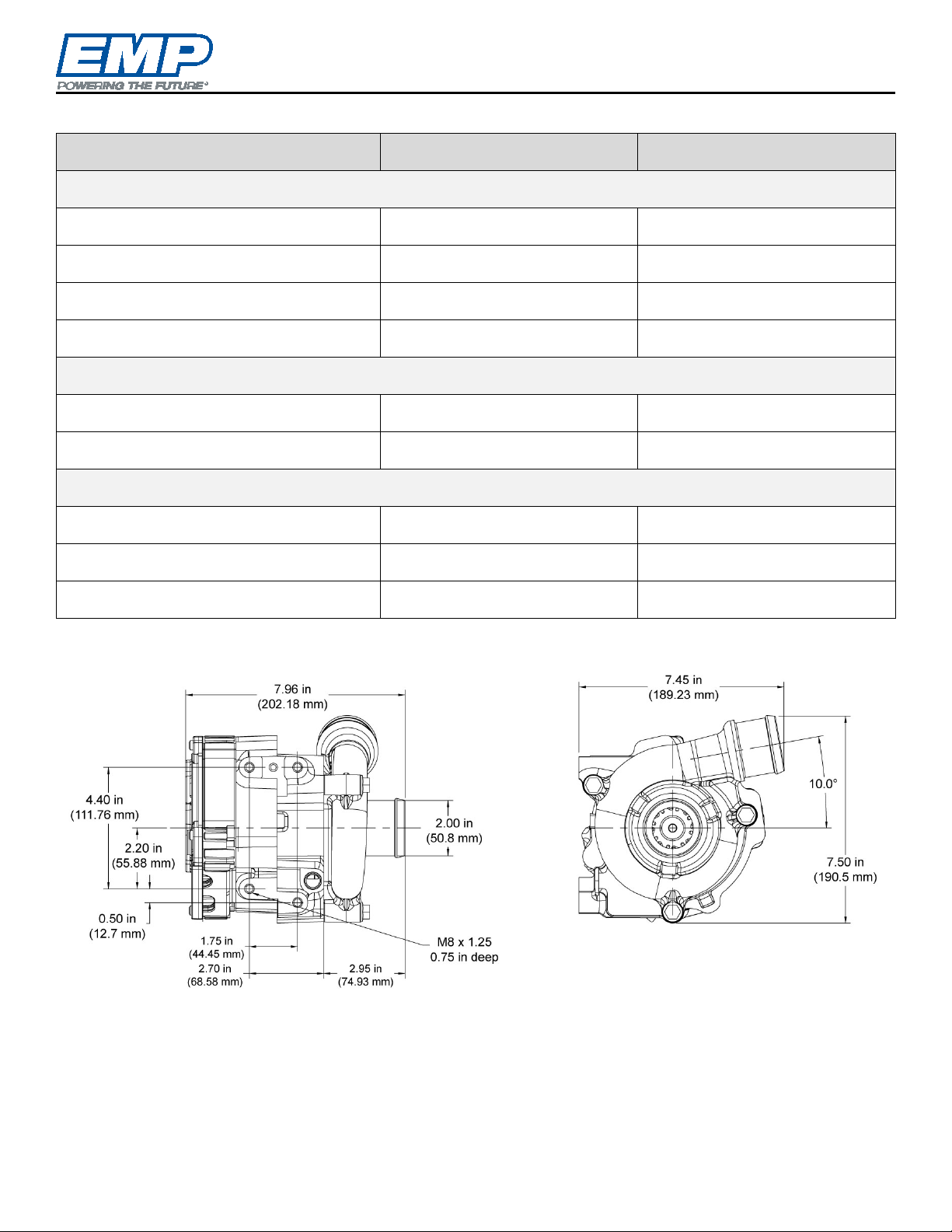
Specifications ....................................................................................................................................................6
Dimensions and Hole Locations/Bolt Spacing ................................................................................................6
Material Listing of Major External and Fluid Contacting Parts.........................................................................7
Operating Limits.............................................................................................................................................7
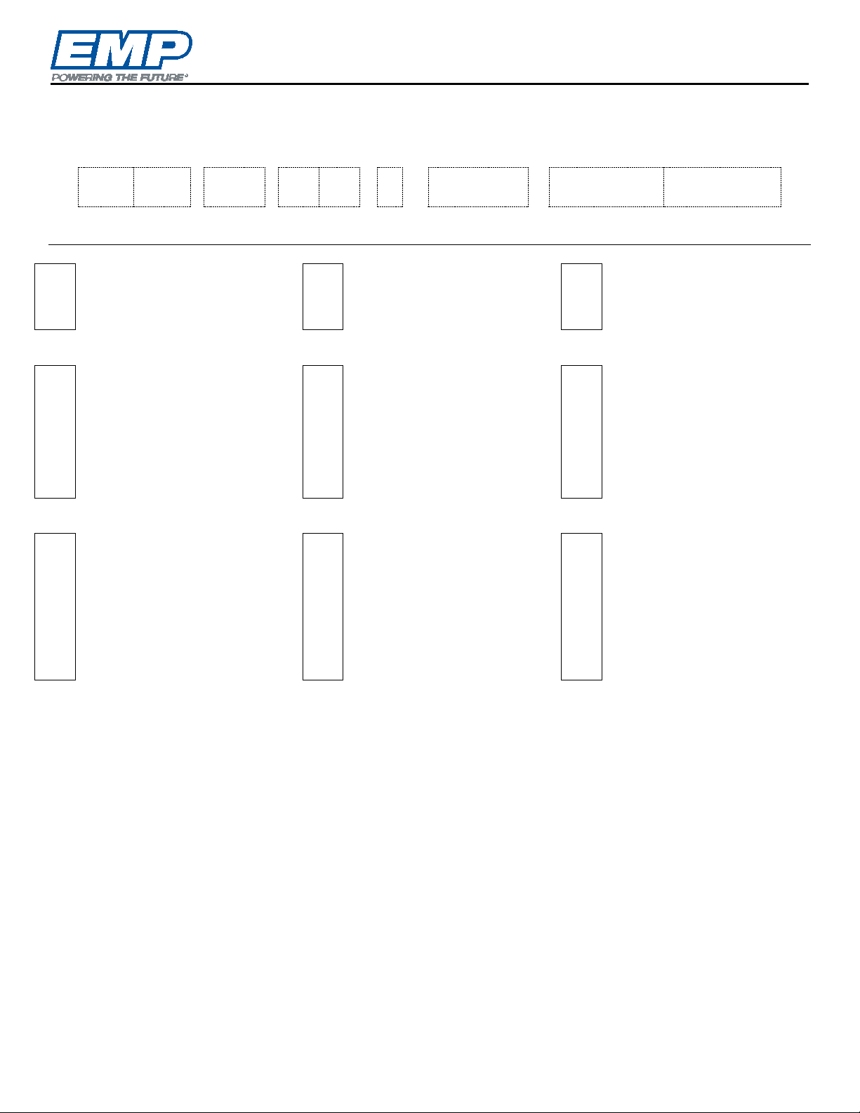
Identification ......................................................................................................................................................8
Product Label.................................................................................................................................................8
EMP Water Pump Model Codes..................................................................................................................... 9
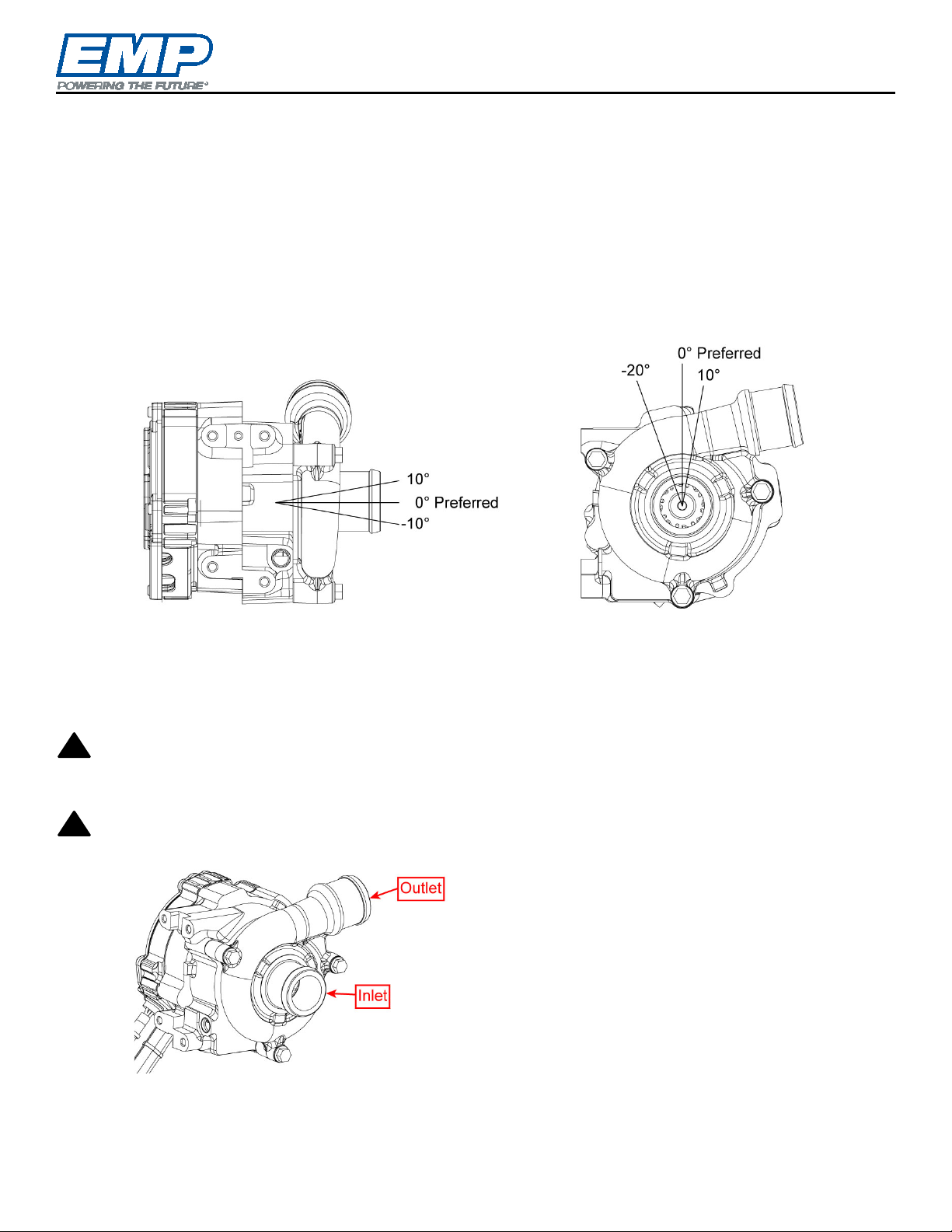
Installation .......................................................................................................................................................10
Environment.................................................................................................................................................10
Orientation ...................................................................................................................................................10
Plumbing......................................................................................................................................................10
System Fill Procedure ..................................................................................................................................11
Wiring...........................................................................................................................................................12
Component Connector Information ..............................................................................................................13
Mating Connector Information ......................................................................................................................13
On/Off Single Speed Control........................................................................................................................15
Routine Maintenance.......................................................................................................................................16
Physical Inspection ......................................................................................................................................16
EMPower Connect™ Service Tool ..................................................................................................................17
Diagnostic Outputs.......................................................................................................................................17
Troubleshooting...............................................................................................................................................17

Introduction
© 2020 EMP, Inc. 4
Introduction
Purpose
The purpose of this quick start guide is to present information related to the pump’s dimensions, electrical
specifications, coolant guidelines, recommended plumbing, mounting orientation, and routine maintenance.
NOTE: For production applications of this product, the full installation specifications must be met. Contact
EMP to request documentation.
NOTE: Orders up to 10 units total can be placed upon completion of the EMP Water Pump Requirements
Form. Orders over 10 units total require a mutually agreed upon 9890085150 Installation Review
Checklist.
Service Technician Responsibilities
Ensure that all safety messages and information messages are read and understood before installation,
maintenance, or repairs are performed. It is important to use caution when service work is performed.
Knowledge of impacted systems and their operation are important before the removal or disassembly of any
component.
Liability Disclaimer
EMP cannot anticipate every possible circumstance that might involve a potential hazard. The safety
messages in this document, in related manuals, and on the product are therefore not all inclusive. If a tool,
procedure, work method, or operating technique that is not specifically recommended by EMP is used, you
must satisfy yourself that it is safe for you and for others. You should ensure that the product will not be
damaged or be made unsafe by the operation, maintenance, or repair procedures that you choose.
Additional Information
Access https://www.emp-corp.com/support/ for service software, service bulletins, service manuals, service
drawings, and other documents related to your installed EMP systems and components. First time users may
create a free customer login at http://www.emp-corp.com/account/register/.
Technical Help
Contact EMP Customer Service for technical help at +1 (906) 789-7497 or service@emp-corp.com.
Warnings, Cautions and Notes
Two headings are used in this document to stress your safety and safe operation of the system. They are
styled with a graphic bullet and bold, uppercase text: WARNING and CAUTION. Warnings highlight
risks to personnel – hazards, unsafe conditions and practices that can result in personal injury or death.
Cautions indicate conditions or practices that can cause damage to components, systems or other equipment.
A third heading, styled as NOTE, calls attention to additional information about components and procedures
discussed in the document.
Definition of Terms
CAN..................Controller area network.
EMPower Connect™ service tool........EMP service tool for diagnostics via PC.
!
!

Product Safety Warnings
© 2020 EMP, Inc. 5
Product Safety Warnings
WARNING: EMP cannot anticipate every possible circumstance that might involve a potential hazard.
The safety messages in this document, in related manuals, and on the product are therefore not all
inclusive. If a tool, procedure, work method, or operating technique that is not specifically recommended
by EMP is used, you must satisfy yourself that it is safe for you and for others. You should ensure that the
product will not be damaged or be made unsafe by the operation, maintenance, or repair procedures that
you choose.
WARNING: Ensure that all safety messages and information messages are read and understood
before installation, maintenance, or repairs are performed. It is important to use caution when service
work is performed. Knowledge of impacted systems and their operation are important before the removal
or disassembly of any component.
WARNING: Make sure the equipment cannot move before doing any work or diagnostic procedures
on the EMP component, system, or vehicle.
WARNING: When working near electric components, ensure they cannot activate unexpectedly.
Remove power or utilize lock out switches.
WARNING: Use extreme caution when working on systems under pressure (i.e. coolant, hydraulic
fluids, air, fire suppression, etc.).
WARNING: Make sure the work area is ventilated and well lit.
WARNING: Make sure charged fire extinguishers are in the work area.
WARNING: Reinstall all safety guards, shields and covers.
WARNING: Make sure all tools, parts and service equipment are removed from the work area.
WARNING: Ensure that all system power and ground connection points are torqued to EMP and/or
OEM specifications to prevent system damage. Failure to follow specified torque requirements can result in
loose connections which can damage electronic components and will void EMP warranty.
!
!
!
!
!
!
!
!
!
!

Specifications
© 2020 EMP, Inc. 6
Specifications
Model 12V 24V
Performance
Operating Temperature Maximum 203 F (95C) 203 F (95C)
Operating Temperature Minimum -40 F (-40C) -40 F (-40C)
Motor Speed Maximum 4200 rpm 4200 rpm
Motor Speed Minimum 1000 rpm 1000 rpm
Mechanical
Component Construction Cast Aluminum Cast Aluminum
Component Weight 15.4 lbs (7.0 kg) 15.4 lbs (7.0 kg)
Electrical
Input Voltage 9-16 V DC (14 V Nominal) 18-32 V DC (28V Nominal)
Operating Current Draw Maximum 65 amps 65 amps
Thermal Protection Auto self protect RPM rollback Auto self protect RPM rollback
Dimensions and Hole Locations/Bolt Spacing

Specifications
© 2020 EMP, Inc. 7
Material Listing of Major External and Fluid Contacting Parts
Item Quantity Description Material Fluid Contact
1 1 Controller Cover Cast Aluminum (413)
2 1 Housing A 356 T6 Yes
3 4 Controller Cover Bolts 18 – 8 Stainless Steel
4 1 Volute A 356 T6 Yes
5 1 Impeller (Internal) 304 Stainless Steel Yes
6 1 Shaft SAE 440 Stainless Steel Yes
7 1 Product Label M - 714
8 2 Connector Nylon
9 3 Volute Bolts Zinc Coated Steel
10 1 Bracket Bolt Zinc Coated Steel
11 1 Bracket 5052 Aluminum
12 1 Water Seal Faces Carbon /Silicon Carbide Yes
13 1 Water Seal Stamping AISI 304 Yes
14 1 Bellows/Cup HNBR Yes
15 1 Spring AISI 302 Yes
Operating Limits
Temperature Limitations
Maximum Fluid and Ambient Operating Temp 203F (95C)
Minimum Fluid and Ambient Operating Temp -40F (-40C)
Maximum Ambient Storage Temp 257F (125C)
Minimum Ambient Storage Temp -40F (-40C)
* If the intended application fluid temperature exceeds 95°C, installation must
be reviewed and approved by EMP to ensure warranty coverage See the
Installation Review Checklist.
NOTE: Over-temperature Protection - To protect the controller, the motor speed begins to derate when
the internal controller temperature reaches a calibrated threshold. Derated motor operation will continue
until the internal controller temperature drops below a safe value.

Identification
© 2020 EMP, Inc. 8
Identification
The component serial information is located on the product label, which is attached to the component. The
serial number can be used to trace the component hardware configuration, software calibration, the date of
manufacture, and manufacturing data.
Product Label
The product identification label is attached to the controller housing next to the electrical interface of the pump.
The product label contains model information.

Identification
© 2020 EMP, Inc. 9
EMP Water Pump Model Codes
Example: WP150-24V-SH-A
WP
150
-
24V
-
S
H
-
A
[OEM]
[CERT]
[Suffix]
1
2
3
4
5
6
7
8
9
1
Component
WP = Water Pump 4
Shaft
C = Carbon
S = Stainless
7
OEM
Omit if n/a
-----------------------------------------
---------------------------------------
----------------------------------------
2
Model
29
32
120
150
5
Orientation
H = Horizontal
V = Vertical
D = Dual
C = Cartridge
See manual for definition
8
Certifications
Omit if n/a
-----------------------------------------
---------------------------------------
----------------------------------------
3
Voltage
6
I/O
A = Address Input
C = Temperature Input
B = Address or Temp Input
(Specified in Calibration)
P = Pressure
M = PWM High (modulated)
L = PWM Low (modulated)
9
Suffix
Denotes model variation
-------------------------------------
------------------------------------
------------------------------------
WP150-24V-SH-A = Water Pump model 150, 24 Volt, Stainless shaft, Horizontal orientation, addressable via
external resistors.
NOTE: All EMP water pumps use CAN communication.

Installation
© 2020 EMP, Inc. 10
Installation
Environment
Environment cleanliness is crucial to pump life. The WP150 is fully submersible. Shielding may be required to
ensure debris does not enter the weep hole. If you have any questions regarding your installation contact EMP
to ensure warranty coverage.
Orientation
WP150 pump is orientation specific and must be installed per EMP guidelines. If you have any questions
regarding pump orientation please contact EMP to ensure warranty coverage.
Pump Orientation
Plumbing
Pump Inlet must be plumbed using 50mm (2.0 inch) diameter hose and/or thin walled tubing from the fluid
supply to the pump inlet.
CAUTION: Localized high spots in the plumbing may cause air to be trapped in the pump causing the
pump to be air locked. The result of air trapped in the pump is loss of prime and no fluid moving resulting
in water seal damage or potential system component damage.
CAUTION: EMP warranty does not cover seal damage due to low lubrication.
!
!

Installation
© 2020 EMP, Inc. 11
Hose Clamps
When making the inlet and outlet hose connections to the pump it is strongly recommended to use SAE312CT
worm drive type hose clamps. Torque worm drive clamps to 90 in-lbs per SAE J1508. Spring type clamps are
not recommended.
System Fill Procedure
CAUTION: Do not run the pump without fluid present. If run dry even for a short period the seal will
be damaged.
CAUTION: Pump may start running upon connection of power, ground and ignition. Do not make
electrical connections until pump and system are filled with fluid.
CAUTION: Systems that are not properly filled may leave air in the pump, creating a condition that
may damage the seal due to low lubrication.
CAUTION: When air becomes trapped in the pump, the pump will not circulate fluid with the
potential to cause damage to components in the system.
CAUTION: EMP warranty does not cover seal damage due to low lubrication.
Approved Fluids
1. Fluids must conform to ASTM D6210-10 or ASTM D3306 for quality and maintenance.
2. Use of coolants containing silicates and phosphates can lead to reduced pump seal life and gel formation
in cooling system components.
3. Use of organic acid technology (OAT) coolants that are silicate and phosphate free will maximize pump
seal life.
4. Customer must verify all WP150 fluid contacting parts are compatible with system components and the
coolant selected for the application.
5. For best results cooling system materials, coolant working life, operating temperature range and other
system details should be reviewed with coolant manufacturer to ensure the proper coolant selection.
NOTE: Use distilled water to dilute coolant or use pre-mix coolant.
CAUTION: Use of “Stop Leak” or radiator cleaner style system additives is not approved.
Each time the cooling system is drained
Caution must be taken to ensure the system is refilled properly to prevent running the pump in a dry state.
1. Install pump and piping according to installation instructions.
2. Ensure flow path is open through the entire system.
3. Fill the system with fluid such that the pump is full of fluid and there are no air pockets in the piping
leading to the pump.
4. Run the pump at 4000RPM, ensuring fluid levels are topped off as air is pushed out of the system.
CAUTION: Do not allow the pump fluid supply to become empty. The fluid level in the surge tank will
drop rapidly at top speed.
5. Verify the pump is moving fluid by observing the input power of the pump during the fill process using
EMPower Connect service tool or a quality amp meter. With the pump operating at 4000 rpm, the input
power must be above 400W (28V and 14A or 14V and 28A). If the pump is below 400W within 1 minute,
turn off pump, purge system air and restart the procedure.
!
!
!
!
!
!
!

Installation
© 2020 EMP, Inc. 12
Wiring
Recommended Wiring Practices
•Wiring or electrical harness must not rub on sharp edges.
•The electrical harness should not be stressed at connections.
•The voltage drop between the battery and the pump should not exceed 5% of the rated battery voltage.
This should be verified at the pump’s maximum current draw.
•Wiring or electrical harness must not rub or make contact with a hot surface. There should be 5"
minimum clearance from the exhaust.
•Wiring or electrical harness should be supported at least every 18" to 20".
•To avoid possible fire or shock, do not pinch any wiring or electrical harnesses.

Installation
© 2020 EMP, Inc. 13
Component Connector Information
Power/Ground Connector: 2-Way Male
Delphi Power Pack 1000 Sealed
Pin
Wire Size and Color
1
8 AWG Black/Red
2
8 AWG Black
Communication Connector: 6-Way Male
Molex MX150 Sealed Key B
Pin
Wire Size and Color
1
16 AWG Black with stamped “PPL” (Purple)
2
16 AWG Black with stamped “TAN” (Tan)
3
16 AWG Black with stamped “WHT” (White)
4
16 AWG Black with stamped “YEL” (Yellow)
5
16 AWG Black with stamped “GRN” (Green)
6
Unused
Mating Connector Information
The following notes apply to all connectors:
NOTE: All cavities in the mating connector must
either be terminated or plugged to prevent
moisture from entering the component.
NOTE: Do not disconnect the component while it
is running. Stop running the component prior to
disconnecting the connector.
Power/Ground Connector: 2-Way
Female Delphi Power Pack 1000 Sealed
– (Delphi 13849756)
Detail
Delphi Part Number
Connector 13849756
Seal 13675511
TPA 13849786
Power Pack 1000 Terminal 13675583
Communication Connector: 6-Way
Female Molex MX150 Sealed Key B -
(Molex P/N 33472-0607)
NOTE: Refer to the appropriate schematic
section to determine the parts needed for
assembling the mating connector for your
application.
Detail Molex Part Number
Connector 33472-0607
Plug 34345-0001
Terminal, MX150, Socket,
18 – 20 AWG
33012-2002
Terminal, MX150, Socket,
14 – 16 AWG
33012-3001
Service kits are available from EMP. The service kit
parts are listed on the next page.

Installation
© 2020 EMP, Inc. 14
Mating Connector Kits Available from EMP
3170073073 – 12” Power and Ground
Connector Replacement Harness
1370073182 – 12” Power and Ground
Connector Replacement Harness and
Communication Connector Parts
1370073183 – Connector parts only for
Communication and Power and
Ground Connectors
NOTE: Prior to mating component Power/Ground connectors, ensure the two seals (green) and the two
seal retainers (white) are in place as shown below.

Installation
© 2020 EMP, Inc. 15
On/Off Single Speed Control
NOTE: All cavities in the mating connector(s) must either be terminated or plugged to prevent moisture
from entering the component.
Pin Usage - On/Off Single Speed Control
Connector
Pin
Purpose
Power/Ground
1
Battery Power
2
Ground
Communication
1
Ignition Enable
2
Unused
3
Unused
4
Unused
5
Unused
6
Unused
Example On/Off Application Schematic
NOTE: EMP recommends fusing the 8 AWG battery conductor near the power source.
(1) 18 AWG wire can be used for the communication connections.
Electrical Connections
Power is supplied from a 12V or 24V DC (nominal)
source depending on component model type and is
received through the 2 way connector (Reference
Component Connector Information and the
example on/off application schematic). The ignition
enable is a switched power source which is sent
from your system to initiate operation of the
component. This can be wired directly to a vehicle
ignition, to a PLC output, through a manual switch
or through a thermal switch. This line will draw less
than 10 mA of current. All switches on this line can
be sized based on this amperage requirement. This
input should be fused close to the source to protect
the vehicle or system wiring.
Operation
When power is on and ignition enable is on, the
component will run in an on/off, single speed
manner. The speed at which the component will run
will be the pre-configured default speed. EMP also
provides a “Power Hold” option which can keep the
controller running for a specified amount of time
after the ignition enable has been removed. This
allows for post-shutdown cooling.
NOTE: If you have any questions with your
calibration settings, please contact EMP Technical
Service at service@emp-corp.com and provide a
serial number for the part in question.
NOTE: See Installation Manual WP150 Electric
Water Pump, EMP document 9970134020 for
additional operation information including
installation for use on a CAN bus.

Routine Maintenance
© 2020 EMP, Inc. 16
Routine Maintenance
Frequency
Action
When checking/filling vehicle
fluids
Ensure fluid levels are correct. Low fluid can cause a pump seal failure.
Every engine oil change Inspect cooling system for leaks. Sample coolant and check to ensure coolant meets
minimum coolant quality requirements. Before removing the pump, evaluate the leak
using the methods outlined in the physical inspection of this document.
Every three months or more
often if conditions are harsh*
Visually inspect exterior of pump and ensure weep holes are not clogged by debris.
Check wires for wear or frayed insulation. Ensure all electrical connections are tight.
Annually+
Ensure connections are tightened to proper torque rating. Ensure all wires and pin
connections are intact. Inspect support structure for any damage or loose hardware.
+ Inspections should also be conducted after any service to the unit.
Physical Inspection
CAUTION: Do not run the pump without fluid present. If run dry even for a short period the seal will
be damaged.
CAUTION: Pump may start running upon connection of power, ground and ignition. Do not make
electrical connections until pump and system are filled with fluid.
1. Make sure the weep hole port is not clogged with debris. If the weep holes is plugged then open it up.
Weep Hole Port
!
!

Empower Connect Service Tool/Troubleshooting
© 2020 EMP, Inc. 17
EMPower Connect™ Service Tool
EMP Service Suite is available at no cost on the EMP website. To use the EMPower Connect service tool,
download and install the Service Suite software on your Windows PC. EMPower Connect software allows the
user to monitor operation, manually control the component and collect history data from the controller. Use
breakout harness 3170073176 to interface with the power and ground and communication connectors and an
RP1210 compatible data link adapter.
The Service Suite User Guide and Tutorial, including connection and control instructions, is embedded in the
software and available on the EMP website.
Diagnostic Outputs
Operational and diagnostic information can be gathered using EMPower Connect service tool via an RP1210
compatible data link adapter. Components using SAE message formats have diagnostic outputs as defined in
section 4.2 of EMP document 9980001068.
Troubleshooting
Symptom
Check
Pump not running
•Check electrical connections.
•Check ignition wire.
•Check if ignition wire is “on”.
•Verify pin location.
Pump is running but not pumping
fluid
•Check system fluid level.
•Check for tubing restrictions (kinks).
•Make sure pump is primed.
•Check for collapsed inlet or outlet hose.
•Check pump inlet for trapped debris.
No CAN communication and/or
pump not responding to CAN
commands
•Check communication harness wiring.
•Verify that CAN messages are being transmitted in the proper formats.
•Verify that the proper component CAN address is being used.
Suspected water pump seal leak
•
Reference Service Bulletin Electric Water Pump Inspection and Diagnostic
Procedures,EMP document 9910085143.
Water pump seal leak
•Verify coolant level.
•Verify coolant selection (for water seal life OAT, phosphate free, silicate free
coolant is recommended).
•Sample coolant and review coolant maintenance records.
•Verify system is not aerated (Reference document 9910085145, Fill D&D Test
and Acceptance Criteria).
•Check for cavitation and low inlet pressure.
Table of contents
Other EMP Water Pump manuals
Popular Water Pump manuals by other brands

Sauer Danfoss
Sauer Danfoss 51 Series manual

Stuart Turner
Stuart Turner mainsboost MBF 60-1-15 Installation & maintenance instructions

Mouvex
Mouvex S4C Installation operation & maintenance

Metso
Metso Orion Series Operation & maintenance manual

Zoeller
Zoeller Z62 HD Series owner's manual

LR-Cal
LR-Cal LPP 700 operating manual

Wilo
Wilo HiDrainlift 3 Series Installation and operating instructions

Blagdon Pump
Blagdon Pump 25 Series Service and operating manual

Grundfos
Grundfos CREC Installation and operating instructions

Ranger
Ranger RD-20SE Installation and operation manual

Gardena
Gardena 8000/4 4T operating instructions

Graco
Graco 234019 Instructions-parts list