AXIOMA METERING UAB QALCOSONIC E4 User manual

AXIOMA Metering UAB
ULTRASONIC HEATING AND COOLING
ENERGY METER
QALCOSONIC E4
TECHNICAL DESCRIPTION AND OPERATION GUIDE
PEE4V02
KAUNAS

PEE4V02 2021-01-27
2
Table of contents
SAFETY REQUIREMENTS............................................................................................................3
1APPLICATION FIELD.............................................................................................................4
2TECHNICAL SPECIFICATIONS.............................................................................................6
3OPERATING PRINCIPLE.......................................................................................................9
4MARKING AND SEALING......................................................................................................9
5INSTALLATION PROCEDURE ............................................................................................11
6OPERATION PROCEDURE .................................................................................................17
7VERIFICATION.....................................................................................................................30
8TRANSPORTATION AND STORAGE..................................................................................30
Annex A...................................................................................................................................31
Annex B...................................................................................................................................34
Annex C...................................................................................................................................40
MANUFACTURER’S WARRANTY...........................................................................................43
For EU Customers only - WEEE Marking
Marking of electrical and electronic equipment in accordance with Article 14 (2) of Directive
2012/19/EU
It is prohibited to dispose a meter marked with this sign into an unsorted
municipal waste container together with other waste!
This symbol on the product indicates that it will not be treated as household waste.
It must be handed over to the applicable take-back scheme for the recycling of
electrical and electronic equipment. For more detailed information about the
recycling of this product, please contact your local municipal office

PEE4V02 2021-01-27
3
SAFETY REQUIREMENTS
Before operating the meter, this Technical Description and the User Manual must be read and
their instructions must be observed.
•When the meter is powered from a battery (3.6 V), the risk to safe operation is posed
only by the heat carrier, which may have a pressure of up to 1.6 MPa and a temperature of
up to 90 oC.
•When the meter is powered from the mains (230 V), an additional risk is posed by life-
threatening alternating current. The meter must be installed and maintained in accordance
with the requirements of the Safety Regulations related to the Operation of Electrical
Installations.
•Meters can be installed and maintained only by specialists who have required
qualifications (to work with electrical installations of up to 1000 V) and permits, are familiar
with the technical documentation for the heat meter, and have received instruction briefing
on work safety.
•No protective grounding is provided for because the housing of the electronic unit
complies with the requirements of Protection Class II.
•Unauthorised dismantling or repair of the device is prohibited.
•Safety guarantees at installation and service of meter is:
- Reliable insulation of electrical circuits,
- Hermetic fitting of primary flow and temperature sensors into the pipeline,
- Reliable fastening of sub-assemblies of heat meter at installation.
•The repair, replacement, connection, and disconnection of the sub-assemblies of the
meter may only be possible after disconnecting from the mains (when the electronic
unit is powered from 230 V mains) and having made sure that there is neither
pressure nor heat carrier in the pipeline.
•When the meter is powered from 230 V mains:
- Meter is connected to 230 V mains by a double-wire copper cable with a diameter of
2 × 0.25 mm2(a non-detachable cable is included in the supply package of the
meter).
- Meter should be connected to 230 V mains through a single-pole automatic 1A
alternating current switch.
- Automatic switch should be a part of the installation of the building. The automatic
switch should be marked as a meter disconnecting device and should be installed near the meter in
a position easily accessible by the meter servicing operator.
The meter and its parts should be installed so that not to hinder the use of the
automatic switch.
It is recommended that the switches for disconnecting power supply be installed in the
same cabinet and adapted to the power used by the device.
•Operating conditions:
–ambient temperature from +5 oC to +55 oC;
–humidity up to 93%.
Caution: If this equipment is used in a manner not specified by the manufacturer, the
protection provided by the equipment may be impaired!

PEE4V02 2021-01-27
4
1 APPLICATION FIELD
The ultrasonic heating and cooling energy meter QALCOSINIC E4 (hereinafter referred to as
“the meter”) is designed to measure the consumption of heating and cooling energy and record data in
two separate registers. It is used in individual or district heating facilities (residential buildings,
enterprises, organisations or supply facilities, etc.) for the commercial metering of consumed energy
where water is the heat carrier.
Microprocessor-based compact meter for installation in either the supply or return heat
exchange circulating system, with replaceable (corresponding the requirements of the technical
regulations for measuring instruments) temperature sensors.
This is microprocessor-based meter for optional mounting on either a supply or return heat
exchange systems. The meter is available in two designs: with permanently connected temperature
sensors or with changeable temperature sensors (complying with the requirements of the Measuring
Instruments Regulations)
The meter complies with the requirements of Annex 1, Annex MI004 to the Technical Regulation on
Measuring Instruments and harmonised standards LST EN 1434 –Heat meters (LST EN 1434-
1:2015+A1:2019, LST EN 1434-2:2015 +A1:2019, LST EN 1434-3:2016, LST EN 1434-4:
2015+A1:2019, LST EN 1434-5: 2015+A1:2019). The meter meets the requirements of Environmental
Class C according to LST EN 1434-1:2015+A1:2019.
Climatic environmental conditions: Temperature range: from 5 oC to 55 oC;
Humidity: condensing. Location: closed.
Mechanical environment class: M1
Electromagnetic environment class: E2
Meter type code structure:
Meter type code structure (continued):
QALCOSINIC E4 - ----------
Type
Accuracy
class:
Min value of temperature
difference:
Ratio of the flow rates
(qp/qi):
Code
2
3 K
100 (standard)
3
250*
4
* except sensors qp=0,6 m3/h and qp=3,5 m3/h with connection G1 ½
Flow sensor (permanent flow rate qp, mounting length L, connection type):
qp, m3/h
L, mm
Connection
Code
0,6
110
G ¾
11
1
110
G ¾
12
1,5
110
G ¾
13
1,5
130
G1
21
2,5
130
G1
22
3,5
260
G1 1/4
40
3,5
260
G1 1/2
42
6
260
G1 1/4
45
6
260
G1 1/2
46
Integrated communication interface type:
Code
Mbus (standard)
1
Mbus and wMbus RF 868 MHz
3
Power supply source type:
Code
Module 24V AC/DC
6
Module 24V AC/DC + mains unit 230 VAC
7
Internal battery (two.) (standard)
8
Length of the flow sensor cable:
Code
1,2 m (standard)
1
Extra communication interface:
Code
Not included (standard)
0
MODBUS (RS485)
2
BACnet (RS485)
5
LoRa 868 MHz RF 868 MHz
6
Protection class:
Code
IP65 (standard)
1
IP68
3

PEE4V02 2021-01-27
5
When ordering, in addition, the following is selected:
- meter initial configuration variant from the list:
Purpose of the meter:
Flow sensor installation:
Energy Meter for Heating
In supply pipe
In return pipe
Energy Meter for Heating
In supply pipe
and Cooling
In return pipe
Energy measurement units and resolution:
0,001 MWh
0,001 GJ
0,001 Gcal
1 kWh (standard)
Communication interface wMBus operating mode:
T1 without AES key
T1 with fixed AES key
T1 with individual AES key
S1
Pulse input / output configuration:
Standard profile configuration (standard)
1-input, 2- input
1-input, 2- output
- meter assembly variant from the list:
Mountig kit for temperature sensors
None (standard)
Valve for DS type (DN15-25) or Pocket (DN32-100)
Mounting set for flow sensor
Only gaskets (standard)
Threaded fittings with gaskets
Length of the temperature sensors cable
Code
1,5 m (standard)
1
3 m
4
5 m
5
10 m
6
Heat carrier type:
Code
Water
1
Configuration profile:
Code
Transportation Mode (Standard)
02
With turned off Transport Mode
05
Pulses inputs/outputs:
Code
No (IP65) (standard)
1
Yes (IP65)
2
Tipo kodas: QALCOSINIC E4 - ----------

PEE4V02 2021-01-27
6
2 TECHNICAL SPECIFICATIONS
2.1. Energy measurement
Accuracy class: 2 according to LST EN 1434-1
Energy measurement units: kWh; MWh; GJ; Gcal
Maximum value of thermal power: 976 MW
2.2. Flow measurement
Ratio of the permanent flow rate to the lower limit of the flow-rate (selectable by the user):
qp/qi =100 (standard) or qp/qi =250 (except for qp =0.6 m3/h and qp 3.5 m3/h with G 1 ½ end
connection)
The technical data of the flow sensor are provided in Table 1.1.
1.1 Table
Permanent
flow rate qp,
m3/h
Upper
flow-rate qs,
m3/h
Lower
flow-rate
qi, m3/h
Threshold
value of
flow rate,
m3/h
Length of
the flow
sensor L,
mm
Pressure
losses at
qp, kPa
Joining to the pipeline
(Thread –G,
flange–DN)
0,6
1,2
0,006
0,003
110
7
G3/4“
1
2
0,004
0,003
110
11,3
G3/4“
1
2
0,01
0,003
110
11,3
G3/4“
1,5
3
0,006
0,003
110
15
G3/4“
1,5
3
0,015
0,003
110
15
G3/4“
1,5
3
0,006
0,005
130
7,2
G1“
1,5
3
0,015
0,005
130
7,2
G1“
2,5
5
0,01
0,005
130
19,8
G1“
2,5
5
0,025
0,005
130
19,8
G1“
3,5
7
0,014
0,007
260
7
G1 1/4“
3,5
7
0,035
0,007
260
7
G1 1/4“
6
12
0,024
0,012
260
20
G1 1/4“
6
12
0,06
0,012
260
20
G1 1/4“
3,5
7
0,035
0,012
260
2
G1 1/2“
6
12
0,024
0,012
260
6
G1 1/2“
6
12
0,06
0,012
260
6
G1 1/2“
Temperature limits of heat conveying liquid: 0.1 oC –90 oC
Length of the connecting cable between the flow sensor and electronic unit: 1.2 m
Maximum admissible working pressure (nominal pressure PN): 16 bar
If the flow-rate exceeds the maximum value qs:
–when the flow-rate < 1.2∙qs, the flow-rate measurement and calculations are continued;
–when the flow-rate > 1.2∙qs, calculations are performed using flow-rate value 1.2∙qs, the
error “exceeded maximum flow-rate” is recorded and the duration of that error is calculated.
2.3. Pulse inputs (additional)
–the number of pulse inputs: 2
–indicated units: m3
–pulse value programmable from list:
0,001; 0,002; 0,0025; 0,005; 0,01; 0,02; 0,025; 0,05; 0,1; 0,2; 0,25; 0,5; 1; 2; 2,5 ; 5; 10 m3
–input pulse types: IB according to LST EN1434-2
–maximum permissible frequency of input pulses: 3 Hz
–maximum permissible voltage of input pulses: 3 V
–condition of maintenance of high level: 3 V through 2 MΩ resistor
–a connected 1.5 m cable is included in the meter for connecting the pulse inputs.
2.4. Temperature measurement
Temperature measuring range: 0 oC …90 oC.
Temperature difference measuring range: 3 …70 K
Temperature sensor design: DS type according to EN1434-2
Connected cable length: up to 10 m.
Platinum resistive temperature sensors Pt500 in accordance to EN60751 are used. Temperature
sensors are paired according to EN1434 and MI004 requirements, the connection method is two-wire.
Note: The lower limit of temperature difference measurement of the pair of temperature sensors
must correspond to the lower limit of temperature difference marked on the meter and the cable diameter
must be within 4.0 ... 4.2 mm.

PEE4V02 2021-01-27
7
2.5. Display
A liquid crystal, 8-digit display for the representation of the values of the indicated parameter and for
the representation of parameters, units of measurement, and operating modes with special symbols.
Integral and instantaneous measured parameters as well as data read from the meter archive and
configuration information specified in Paragraph 6.3 are displayed.
Energy measurement units (selectable by the user when installing): kWh, MWh, Gcal, or GJ
Resolution of energy indicators (selectable by the user when installing):
000000,01 kWh (only for meters with qp≤1,5 m3/h )
0000000,1 kWh
00000001 kWh,
00000,001* MWh (Gcal or GJ)
000000,01 MWh (Gcal or GJ)
0000000,1 MWh (Gcal or GJ) (only for meters with qp≥1,5 m3/h )
*- manufacturer’s standard setting.
Resolution of volume indicator: 00000,001 m3
In the case of battery discharge or disconnection, all integral readings and archive data shall be
saved for at least 16 years and can be accessed by connecting a power battery in the operating condition.
2.6. Data recording and storage
In its memory, the meter accumulates an archive of hourly, daily, and monthly-measured parameters.
Archive data can be read only by remote data reading means (see Paragraph 6.5). The monthly data archive
parameters which are also additionally showed on the display are specified in Paragraph 6.3.1.
The following parameters of each hour, day, and month are accumulated in the memory of the meter:
Integral energy
Integral cooling energy
Integral energy, Tariff 1
Integral energy, Tariff 2
Integral heat carrier volume
Integral value of Pulse Input 1
Integral value of Pulse Input 2
Value and date of the maximum power
Minimum (or maximum cooling) power value and date
Value and date of the maximum flow-rate
Supply heat carrier maximum temperature value and date
Return heat carrier maximum temperature value and date
Supply heat carrier minimum temperature value and date
Return heat carrier minimum temperature value and date
Minimum recorded temperature differential and date
Supply heat carrier average temperature value
Return heat carrier average temperature value
No-energy operation calculation error time
Summary error code
Time when flow-rate exceeded 1.2 qs
Time when flow-rate was below qi
Archive capacity, minimum:
for hours archive records: 1480 h
for days archive records: 1130 days
for months and years archive records: 36 months
Archive data storage time: at least 36 months
Time of storage of all measured integral data, also without power supply to the electronic unit:
at least 16 years
2.7. External communication interfaces
Interfaces are always included:
Optical interface
Mbus interface
Ordered interface:
RF 868MHz (wMbus S1 or T1) interface
Additional interface (depending on the order; only one option from the list is possible):
MODBUS (RS485)
BACnet (RS485)
LoRa RF 868 MHz

PEE4V02 2021-01-27
8
The interfaces are intended for data reading and meter parametrisation. When the meter is
configured for being powered only from the internal battery, the time of communication through the additional
interfaces is automatically limited to save the battery –16 hour per month on an average. Unused
communication limit is summed up. If the limit is used out, the interface is locked and the summing-up of a
new limit will start only after the change of the hour (80 seconds each hour).
For the wired interfaces a permanently connected 1,5 m length cable is included in the meter.
The optical interface is integrated in the front panel of the electronic unit and is intended for data
reading in Mbus protocol, meter parametrisation, and output of optical pulses in the test mode. It is activated
by pressing the button (5 minutes after the end of communication, or is automatically disabled after pressing
the button).
2.8. Pulse outputs
Number of pulse outputs: 2 or no (to be specified when ordering)
Class: OB –in the operating mode , OD –in the test mode
Type: open collector, current up to 20 mA ,voltage up to 24 V
Pulse duration: 125 ms –in the operating mode, 1.2 ms –in the test mode
Pulse value in the operating mode:
–when the output is configured for energy, the value of its pulses can be selected from the list:
Energy measurement units
Possible values for the energy pulse *
„kWh“ or „MWh“
0,00001; 0,0001; 0,001; 0,01; 0,1; 1; 10; 100; 1000; 10000 MWh/pulse
„GJ“
0,0001; 0,001; 0,01; 0,1; 1; 10; 100; 1000; 10000 GJ/ pulse
„Gcal“
0,0001; 0,001; 0,01; 0,1; 1; 10; 100; 1000 Gcal/imp
*- lenth of values list depends of permanent flow rate and LCD energy value comma position
–When the output is configured for water quantity, the value of its pulses can be selected from the list :
0,001; 0,01; 0,1; 1; 10 m3/pulse
–a connected 1.5 m cable is included in the meter for connecting the output pulses .
2.9. Meter power supply
-two internal AA-size 3.6 V lithium (Li-SOCl2) batteries with a service life of at least 15+1 years,
-or an external 12–42 V DC or 12–36 V 50/60 Hz AC voltage; consumption current
not more than 20 mA. Mains unit 230 VAC can be added.
2.10. Overall dimensions:
electronic unit: max 115 mm x 90 mm x 30 mm,
flow sensors: according to Annex B
Weight of the meter:
Connection type (and length) of the flow sensor
Weight of the meter, maximum, kg
G3/4“
0,4
G1“
0,5
G1 ¼“
0,6
G1 ½ “
0,8
2.11. Operation conditions
Electronic unit and flow sensor protection class: IP65 (standard) or IP68
Temperature sensors protection class; IP68
Operating conditions:
–ambient temperature 5 oC to 55 oC;
–relative humidity up to 93 ,
–atmospheric pressure 86 kPa to 106.7 kPa
Mechanical environment class: M1
Electromagnetic environment class: E2.

PEE4V02 2021-01-27
9
3 OPERATING PRINCIPLE
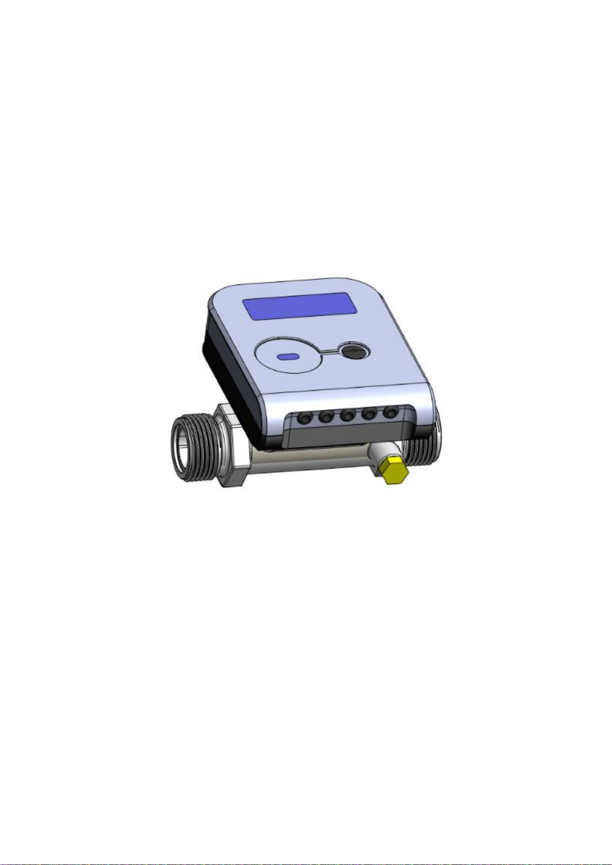
The flow-rate is measured on the basis of the ultrasonic measurement principle. The ultrasonic
signal is sent along the flow sensor upstream and downstream between the ultrasonic sensors, which
alternately perform transmitter and receiver functions. The flow rate is calculated on the basis of the
measured propagation time difference (downstream and upstream).
The temperature differential between the supply and return flows is measured by resistive
temperature sensors. The electronic unit calculates the amount of consumed heat energy by integrating over
time the difference of the enthalpies of supply and return heat carrier and provides the data on the display.
Energy calculation formulas:
–when the flow sensor is in the supply line
Q = Vρ1(hT1-hT2)
–when the flow sensor is in the return line
Q = V ρ2(hT1-hT2)
Where: Q –heat energy;
V –the volume of water passing through the meter, m3;
ρ1, ρ2 –the water density corresponding to the supply and return heat carrier temperatures
Θ1 and Θ2 measured by the supply and return water temperature sensors T1 and T2;
hT1, hT2 –the calculated specific enthalpy of the heat carrier for the temperatures Θ1 – Θ2.
When the cooling energy tariff function is activated, in case of a negative temperature differential, energy will
be accumulated in the additional tariff register Q☼. In this case, energy values are calculated according to the
following formulas:
–when the flow sensor is in the supply line
when Θ1 > Θ2: Q = V1(hT1-hT2), Q☼= 0
when Θ1 < Θ2: Q☼= V1(hT2-hT1), Q = 0
–when the flow sensor is in the return line
when Θ1 > Θ2: Q = V2(hT1-hT2), Q☼= 0
when Θ1< Θ2: Q☼= V2(hT2-hT1), Q = 0
The electronic unit of the heat meter performs all necessary measurement and data storage functions:
- measurement and collection of thermal energy consumption and heat transfer medium volume,
- accumulation of instantaneous, average, maximum and minimum values of heat flow and temperatures,
- measure and accumulation of volumes according to the received pulses at the two pulse inputs,
- generates energy and volume pulses at two pulse outputs,
- performs automatic diagnostics of the meter and accumulation of operating and measuring errors,
- displays measured and stored data and transmits via telemetry interfaces,
- store the values of thermal energy in separate registers,
- ensures accelerated detection of measurement errors in test and adjustment modes.
4 MARKING AND SEALING
4.1. Marking
The following is indicated on the front panel of the electronic unit of the meter: the manufacturer’s
trade mark, type and the type code of the meter, EU –type examination certificate number, factory number,
year of manufacture, temperature measurement range, temperature difference measurement range,
accuracy, environmental class according to LST EN1434-1, electromagnetic and mechanical environment
class, flow measurement range (qi, qp, qs), temperature range, type of temperature range, maximum
allowable working pressure and the distributor’s mark (if applicable), types of communication interfaces
(excluding optical ones), and supply voltage (in the case of external power supply).
The following is indicated on the housing of the flow sensor:
–the type of connection (thread or relative diameter);
–the flow direction.
Destination of wire communication interfaces , additional inputs and outputs, and wires of external
power cables is marked with the colour of the cable wires and an additional label on the cable indicating the
destination.
The temperature sensor intended for mounting in the higher-temperature pipeline is marked with a red
marking pipeline sign; that intended for mounting in the lower-temperature pipeline is marked with a blue
pipeline sign.
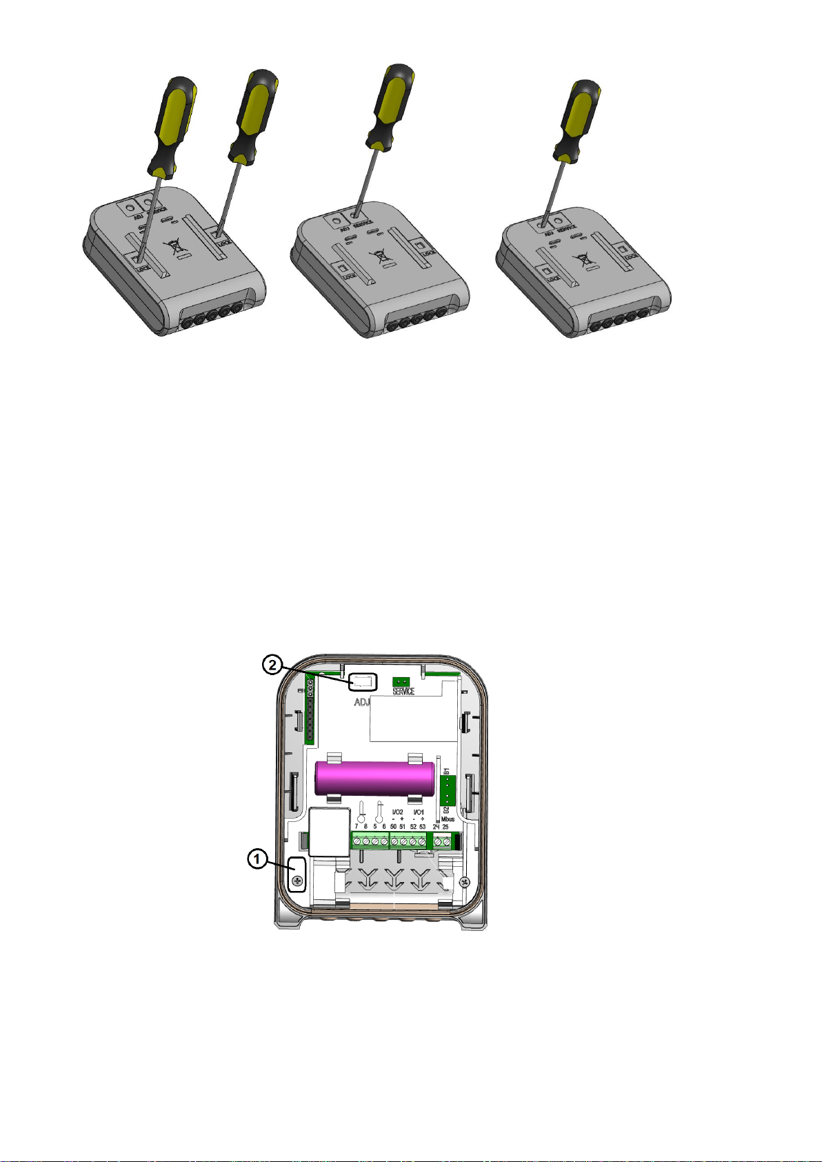
4.2. Sealing of the meter (Annex C)
4.2.1. Sealing of the calculator of the heat meter
Access to the opening elements of the box, the configuration change activation contacts and the
adjustment data change activation contacts is protected by special partitions that can be easily broken with a
tool (such as a universal flat-blade screwdriver) (Fig.4.1).

PEE4V02 2021-01-27
10
a) b) c)
Fig. 4.1 Access to elements fixing the opening of the box (a), configuration change
activation contacts (b) and adjustment data change activation contacts (c)
(partitions easily breakable with a tool)
After the opening of the box, change of the configuration, or adjustment of the meter (when the
special partitions were broken out for this purpose), the opened slots must be additionally sealed with sticker
seals:
-the two slots marked LOCK for access to the elements fixing the opening of the box are sealed with
supplier sticker seals (Fig. 4.1a),
-the slot marked SERVICE for access to the configuration change activation contacts is sealed with
the supplier’s sticker seal (Fig. 4.1b),
-the slot marked ADJ for access to the adjustment data change activation contacts is sealed with the
supplier’s sticker seal (Fig. 4.1c).
In addition, the inspection seals - stickers seal the access to the protective cover fixing screw (1) and
the adjustment data change activation contacts (2) if the protective partition has been broken (Fig. 4.2).
Fig. 4.2 .Sealing the cover of the calculator: the inspection seals /adhesive seals protect the acces
to protective cap mounting bolt (1) and to adjustment data change activation contacts (2) , if breakable
partition is broken out.
4.2.2. Sealing of the flow sensor of the heat meter.
The manufacturer’s warranty sticker seal is attached –the protective cap fastening screws are
sealed (Fig. C2, pos. 1).
4.2.3. After installation, the temperature sensor fastening screw is sealed with mounting seals (Fig. C3).

PEE4V02 2021-01-27
11
5 INSTALLATION PROCEDURE
5.1. General requirements
Prior to installing the meter, it is necessary:
- to check the complete set of the meter with that specified in the technical documentation;
- to check for any visible mechanical defects;
- to check the configuration of the meter and to change it if necessary.
The meters may only be installed by qualified specialists in accordance with the requirements of this
document and the meter installation design.
It is prohibited to lay signal wires near (closer than 5 cm from) power cables or cables of other
devices.
5.2. Check of the configuration of the meter
5.2.1. Prior to installing the meter, it must be verified whether its configuration complies with the
requirements for the specific facility and it must be changed if necessary (if the meter is in the transport
mode, the configuration can also be changed by the press-button or with HEAT3_service configuration
software, without damaging the meter structure or seals). The following parameters are verified (the factory
settings for the meter are their standard ones):
- whether the meter is intended to be installed in a supply or return pipe;
- whether the meter is intended to measure heat energy or heat and cooling energy;
- energy measurement units;
- displayed energy resolution (point position);
- whether the tariff registers are activated and the functioning conditions of the tariff registers;
- whether the pulse inputs are activated, their purpose, pulse values, initial values of their volume
registers, and volume register resolution (point position);
- whether the pulse outputs are activated, their purpose, pulse values, initial values of their volume
registers, and volume register resolution (point position);
- the reporting year and month date;
- the subscriber number;
- the internal clock time;
- Mbus interface addresses and communication speed.
Note. The transport mode will turn off automatically (the possibility to change configuration parameters will
be turned off) when the meter starts operation and the volume integrator has accumulated more than 1 litre.
The transport mode can also be turned off using the button (as like turning on TEST mode) and with the
HEAT3_service configuration software.
5.2.2. Procedure for the review of the configuration of the meter:
- If the meter is in the transport mode, its display is off in the stand-by state. The display is turned on
by pressing the button and, as long as the meter is in the transport mode, it will turn off after 5
minutes (in the normal operation mode, the display is constantly on and constantly shows the value
of measured energy):
00000.000 MWh
INT
- For the review and change of the configuration, press and hold down the button until INF turns on at
the bottom of the LCD. The parameter is selected by shortly pressing the button (and is changed if
necessary):
LCD image
Parameter
Possibility to change
→
0.000 kW
INF
Heat capacity
→ m3h
0.000
INF
Flow-rate
1 →
0 °C
INF
Temperature T1

PEE4V02 2021-01-27
12
2 →
0 °C
INF
Temperature T2
1-2 →
0.0 °C
INF
Temperature differential T1-T2
→
SEt. 0.000 MWh
INF ☼
Installation place
Heat or heat/cooling meter
Energy measurement units and point position
Yes*
Yes*
Yes*
→
b: 2037.03
INF
Battery service life end date
→
2021.07.24
INF
Date (year.month.day)
Yes
→
15-07-32
INF
Time (hour-minute-second)
Yes
→
----. 01. 31
INF
Reporting date of the year (month.day)
Yes
→
----. --. 31
INF
Reporting day of the month
Yes
1
L1 0.0 °C
INF MAX
Parameter of the 1st tariff
Parameter value
Parameter condition
Yes
1
L2 0.0 °C
INF MAX
Parameter of the 2nd tariff
Parameter value
Parameter condition
Yes
1 → m3
In 0.001
INF
Mode of the 1st pulse input/output
Pulse value
Yes
2 → m3
In 0.001
INF
Mode of the 2nd pulse input/output
Pulse value
Yes
1 → m3h
00000.000
INF
Initial reading of the 1st pulse input
Point position of the 1st pulse input
Yes*
2 → m3h
00000.000
INF
Initial reading of the 2nd pulse input
Point position of the 2nd pulse input
Yes*
1 →
buSA 1
INF
Initial address of M-bus protocol of the 1st
wire interface
Yes*
1 →
2400E bPS
INF
Communication speed of the 1st wire
interface, bits per second (E –parity Even)
Yes*
2 →
buSA 1
INF
Initial address of M-bus protocol of the 2nd
wire interface
Yes*

PEE4V02 2021-01-27
13
2 →
2400E bPS
INF
Communication speed of the 2nd wire
interface, bits per second (E –parity Even)
Yes*
→
H: ----
INF
Heat carrier type ( ---- - water)
→
C: 0000000
INF
Subscriber number
Yes
→
SoFt 0.01
INF
Software version number
→
00000000
INF
Meter factory (serial) number
→
0000000.0 h
INF
Error-free meter operation time
→
b:0000000 h
INF
Total operation time of the meter
→
tESt on Wh
INF
For activating the test mode and the output of
energy pulses through the optical interface
Yes**
→ m3
tESt on
INF
For activating the test mode and the output of
volume pulses through the optical interface
Yes**
→
InStALL
INF
For activating the RF interface installation
mode by the press-button (press and hold)
Yes**
Notes.
1) The symbol → shows that the meter is in the transport mode.
2) *the marked parameters are displayed only in the transport mode
3) **the marked parameters can also be changed in the normal operation mode
5.2.3. Change of the configuration of the meter
The parameters marked in Paragraph 5.2.1 can be changed using the configuration programme
HEAT3_service (or and by buttons, if the meter is in transport mode). If the transport mode is turned off in
the meter, to change parameters (except type of energy measurement, measurement units and installation
place), the slot SERVICE should be opened at the back of the electronic unit by breaking the partition and to
short-circuit the contacts inside („TEST“ indication will turn on). By short-circuit the contacts repetedly- the
configuring function will be turned off. After configuration, the slot must be sealed with a sticker seal.
5.3. Electrical wiring
The meter is fully ready for installation, complete with the necessary cables for connection (usually no
need to open the meter).
If the meter is equipped with wired interfaces or a pulse input / output function, appropriate and marked
cables to connect the relevant external device are provided (see Annex A, Figure A1 and Table A1).
If the meter is intended to be powered by an external source of 230V AC, the dedicated and marked
cable of the meter shall be connected to the appropriate source (see Annex A, Fig A1 and Table A1) or to
the mains unit 230 VAC.
If it is necessary to install or replace the meter replaceable modules - open the electronic unit box.

PEE4V02 2021-01-27
14
Opening of electronic unit box
Open the electronic unit by help of universal tool (for example a universal flat screwdriver): by breaking
two protective partitions marked LOCK - see Fig. 5.1., pos. a (or by removing sealing stickers, if the partitions
have already been broken).
In the opened cavity, use a flat screwdriver to tilt the latch to the outside and open the box - see Fig’5.1,
pos. b. Do this one after the other on both sides.
a) Break the protective LOCK b) Lean locking catches to the
outside and open the box
Fig. 5.1. Opening of electronic unit box
Connection of temperature sensors
Only platinum resistive temperature sensors Pt500 in accordance with EN60751, paired and labeled in
accordance with LST EN1434 and MI004, are suitable for use with the meter and are connected by a two-
core cable with an external diameter of 4.0 ... 4.2 mm and lenght up to 10 m.
Open the electronic unit box (Fig. 5.2).
If the meter is supplied with a second battery (located in the temperature sensor connection area),
remove it from the socket, if needed (is allow to disconnect from the meter if necessary).
Install the wires of the temperature sensors through their respective holes, connect them to the marked
terminals and fix the cable into the slots (see Annex A, Fig. A2 and A3). It is important that the temperature
sensor for working in the higher temperature pipe (usually marked in red) is connected to terminals 5 and 6,
the temperature sensor for working in the lower temperature pipe (usually marked in blue) is connected to
terminals 7 and 8.
Install a second battery in to the slot (if any) and verify that it is plugged in (if disconnected).
The electronic unit box is closed by twisting it and squeezing it until it snaps into place. Check if it is
locked firmly (by trying to open).
The LOCK holes has to be sealed with the supplier's seal-sticker.
Connecting additional interface modules
The meter has integrated wireless (RF) and cabled M-bus interfaces and two pulse inputs / outputs.
Meter additionaly can be equipped with an optional interface modules.
Integrated Mbus interface and the pulse inputs / outputs cables is connected in the same order as
when connecting the temperature sensors (see above), only the cable leads are connected to the
dedicated terminals (see Annex A, Fig. A2, A3 and Table A2).
The optional interface module is connected in the following order:
-open the box and install additional/extra interface cable in the same order as when connecting the
temperature sensors (see above),
- the additional interface cable is connected to the terminals of the interface module in accordance with
Table A2,

PEE4V02 2021-01-27
15
- the module is inserted into the appropriate slot on the meter and the side-brackets, the module cable is
firmly slipped into the meter and locked in place by finger-pinching it into the fixture (see Fig. A3),
- plug in and connect a second battery to connector B2,
- the electronic unit box is closed by twisting and squeezing it until it locks into place. Check for firm
locking (when opening).
- the LOCK holes has to be sealed with the supplier's seal.
5.4 Installation
Important: It is forbidden to place the meter signal wires near (less than 5 cm) power cables or other
equipment cables.
5.4.1 Mounting of the calculator
The electronic unit (calculator) of the meter is mounted in a heated room. The temperature of the
working environment should not be higher than 55 oC. It may not be exposed to direct sunlight.
No special requirements are established for the free space around the meter. It is important that nearby
installations or structures do not rest against the housing of the meter, do not hinder the laying of cables and
reading of data on the display. The meter should be installed at a safe distance from other devices emitting
heat or strong electromagnetic field (in order to prevent the disturbance of its working environment
conditions).
The electronic unit is mounted on an auxiliary holder (it can be oriented in the required direction at an
angle of each 90 o:
The possible ways of the mounting of the electronic unit (auxiliary holder):
- Direct mounting on the housing of the flow sensor, by turning each 90o (only when the flow
temperature does not exceed 90 oC):
-

PEE4V02 2021-01-27
16
- On a wall:
- In the electrical equipment cabinet, on a standard DIN rail:
Important: It is prohibited to attach the electronic unit directly on the wall because there is a risk
that moisture may condense on the walls of the room or the temperature of the surface of the wall may
drop below 5 oC. In this case, it is recommended to mount the electronic unit so that to provide for an air
space of at least 5 cm between the unit and the wall surface.
5.4.2 Mounting of flow sensors
The installation and overall dimensions of the primary flow sensors are provided in Annex B.
No straight sections are required.
It is recommended to install flow sensors in pipelines as far as possible from pumps, partitions, and
elbows.
Flow sensors may be installed horizontally, vertically, or in a slope. Mandatory condition: in the
operating mode, the pipe must have a pressure of not less than 30 kPa and the pipe must be fully filled
with water.
In respect of the longitudinal axis of the pipe, flow sensors can be mounted in any positions.
The flow direction and the direction of the arrow on the flow sensor must coincide.
The flow sensor can be installed either on the supply or return line, depending on the indication on the
label of the meter.
Prior to installing the sensor, the pipeline of the heating system must be flushed at the place of the
installation of the sensor.
In order to avoid stresses in the pipelines, the distance between the flanges at the flow sensor installation
place shall correspond to the total length of the sensor with regard to the thickness of gaskets.
It is recommended to select the flow sensor installation place as far as possible from potential
sources of vibration (for example, pumps).
When installing the sensors, attention should be paid to the gaskets in order to ensure that they do not
protrude inward the pipeline.
Tighten the connection nuts to the torque, depending on the size of the connection thread:
G3/4“
G1“
G1 ¼“
G1 ½“
30 Nm
35 Nm
45 Nm
50 Nm
It is prohibited to lay the wires of the flow sensor near (closer than 5 cm from) power cables or cables of
other devices.
5.4.3 Installation of temperature sensors
Temperature sensors are installed with their placement heads upward, perpendicularly to the pipe axis
or at an angle of 45oto the fluid flow direction so that the sensing element is immersed in the medium being

PEE4V02 2021-01-27
17
measured at least to the pipe centreline (see in the figures in Annex C). When the meter is fitted with flow
sensors with flanges G3/4“ and G1“, one temperature sensor is installed in the housing of the flow sensor.
It is prohibited to lay the wires of the temperature sensors near (closer than 5 cm from) power cables or
cables of other devices.
5.5 Check of installation and parameter setting
If the meter (calculator, flow and temperature sensors) is installed correctly, when there is flow, the
display of the meter should represent the flow and temperature readings. In case the readings of the
measured channels are not displayed, the installation of electrical circuits must be checked.
6. OPERATION PROCEDURE
6.1.Control
The representation of measured and information data on the display is selected by the control button located
on the upper part of the electronic unit.
6.2 Representation of data
Data are displayed on a liquid crystal, 8-digit display with special symbols for the representation of
parameters, units of measurement, and operating modes:
When the flow flowing (in the right direction), it is represented by an arrow →; when the flow flowing
in the opposite direction, it is represented by the arrow ←. When there is no flow, no arrow is displayed. The
purpose of other symbols is described in Sections 6.3.1 –6.3.3.
This following information can be displayed:
-the values of the integral and instantaneous measured parameters (when the symbol INT is
displayed),
-the data of monthly archives and data of the reporting day (when the symbol BIL is displayed),
-information on the configuration of the device (when the symbol INF is displayed).
The consumed heat energy is displayed constantly. Other data are represented on the display in a
sequence with the use of the control button.
When the meter is configured for the installation in the supply line, the symbol is displayed;
when the meter is configured for the installation in the return line, the symbol is displayed.
The symbol is shown when there is a significant meter operation error (due to which the
summing-up of energy or normal working time is suspended). For the error code, see the LCD menu
item 1.12 (Paragraph 6.3).
6.3. Menu structure
Control button

PEE4V02 2021-01-27
18
The diagram of the review of readings of the electronic unit in the operating mode is shown in Fig.
6.1. The main integral readings (1.2) or error (1.1) will always be shown if the button was not pressed for
more than 5 minutes.
Fig. 6.1 The diagram of the review ot readings in the operating mode.
6.3.1. Viewing the readings in the operating mode (User Menu)
Note: This is a complete list of represented parameters. It can be shortened at a specific meter for the
convenience of the user.
ID
Parameter
Value
Notes
1.1
Integral heating energy
00000.000 MWh
INT
1.2
Integral cooling energy
00000.000 MWh
INT ☼
1.3
Integral energy, Tariff 1
1
00000.000 MWh
INT
In the case of a combined
device, the “☼” shows that
the tariff is linked with a
cooling energy meter
1.4
Integral energy, Tariff 2
2
00000.000 MWh
In the case of a combined
device, the “☼” shows that
the tariff is linked with a

PEE4V02 2021-01-27
19
INT
cooling energy meter
1.5
Integral heat carrier volume
m3
00000.000
INT
1.6
Integral volume of Pulse Input 1
1 m3
00000.000
INT
1.7
Integral volume of Pulse Input 2
2 m3
00000.000
INT
1.8
Segment test
Changes every second
1.9
No-energy operation calculation
error time
000000.00 h
INT
1.10
User identification number
C:0000000
INT
Matches the secondary
address of MBus interface
1.11
Check number
0000
INT
1.12
Error code and error beginning date
Er: 0001
INT
When there is no error, it only
shows Er: 0000
When there is critical error,
the images
2021.01.01
INT
changes every second: error
code and error beginning date
The error code values are
explained in Paragraph 6.3.3
2.1
Settlement day integral energy and
date
00000.000 MWh
BIL
Changes every second
2021.01.01
BIL
2.2
Settlement day integral cooling
energy and date
00000.000 MWh
BIL ☼
Changes every second
2021.01.01
BIL
2.3
Settlement day integral Tariff 1
energy and date
1
00000.000 MWh
BIL
Changes every second

PEE4V02 2021-01-27
20
2021.01.01
BIL
2.4
Settlement day integral Tariff 2
energy and date
2
00000.000 MWh
BIL
Changes every second
2021.01.01
BIL
2.5
Settlement day integral heat carrier
volume and date
m3
00000.000
BIL
Changes every second
2021.01.01
BIL
2.6
Settlement day integral pulse input
1 value and date
1 m3
00000.000
BIL
Changes every second
2021.01.01
BIL
2.7
Settlement day integral pulse input
2 value and date
2 m3
00000.000
BIL
Changes every second
2021.01.01
BIL
2.8
Previous month integral energy and
date
M
00000.000 MWh
BIL
Changes every second
2021.01.01
BIL
2.9
Previous month integral cooling
energy and date
M
00000.000 MWh
BIL ☼
Changes every second
2021.01.01
BIL
2.10
Previous month integral Tariff 1
energy and date
1 M
00000.000 MWh
BIL
Changes every second
2021.01.01
BIL
2.11
Previous month integral Tariff 2
energy and date
2 M
00000.000 MWh
BIL
Changes every second
Table of contents
Other AXIOMA METERING UAB Measuring Instrument manuals
Popular Measuring Instrument manuals by other brands

Linear Technology
Linear Technology DC2531 Demo Manual

Metro DataVac
Metro DataVac Starsys Assembly instructions

STIEBEL ELTRON
STIEBEL ELTRON EM Meter Installation

DEGREE CONTROLS
DEGREE CONTROLS C Point user manual

Lasermet
Lasermet LS-100-12 instruction manual

Pasco Scientific
Pasco Scientific OS-8537 Instruction manual and experiment guide