EMTEST compact NX5 Series User manual

M a n u a l
F o r O p e r a t i o n
compact NX5
The ultra-compact simulator
and its system modules
compact NX5
Sys App 3.1.0.0 or higher
The compact NX5, whereby well understood NG says Next
Generation, is the most versatile tester to cover transient and
power fail requirements according to international standards
(basic and generic standards) and product family standards.
With the intuitive touch panel, the NX5 is the most economical
solution for tests during development as well as for full-
compliant immunity tests and CE Marking for single phase DUT
with the ability to be extended for testing three-phase DUTs by
means of an automatically controlled external coupling network
up to 200A.
EM TEST supplies a large range of accessories for the various
applications such as magnetic field tests and more.
EN/IEC 61000-4-4
EN/IEC 61000-4-5
EN/IEC 61000-4-8
EN/IEC 61000-4-9
EN/IEC 61000-4-11
EN/IEC 61000-4-12
EN/IEC 61000-4-29
EN 61000-6-1
EN 61000-6-2
Version:
1.06 / 10.01.2017
the benchmark for emc
Replaces:
1.05 / 30.09.2016
Filename:
UserManual-compact-NX 5-E-V1.06.doc
Printdate:
10.01.17

EM TEST Compact NX5
Operating Manual V 1.06 2 / 143
Exclusion for Documentation
Unless specifically agreed to in writing, AMETEK Compliance Test Solutions (AMETEK CTS):
(a) Makes no warranty as to the accuracy, sufficiency or suitability of any technical or other information provided
in its manuals or other documentation.
(b) Assumes no responsibility or liability for losses, damages, cost or expenses, whether special, direct, indirect,
consequential or incidental, which might arise out of the use of such information. The use of any such
information will be entirely at the user’s risk, and
(c) Reminds you that if this manual is in any language other than English, although steps have been taken to
maintain the accuracy of the translation, the accuracy cannot be guaranteed. Approved AMETEK content is
contained with English language version.
The present manual shows suggestions of test setups according to the standards IEC 61000-4-x using
equipment manufactured by EM TEST.
The suggestions do certainly not replace the standards! Variations due to different interpretations of the standard
are possible. The circuits shown in the figures supposed to illustrate the functional principles only and do not
show every single detail of the components.
Manual information
Version / date:
1.06 / 10.01.2017
Replaces:
1.05 / 30.09.2016
Filename:
UserManual-compact-NX 5-E-V1.06.doc
Printdate:
10.01.17
Contact Information
EM Test (Switzerland) GmbH
Sternenhofstrasse 15
4153 Reinach BL1
Switzerland
Phone : +41 61 717 91 91
Fax : +41 61 717 91 99
URL : http://www.emtest.com
Copyright © 2017 EM Test (Switzerland) GmbH
All right reserved.
Information in earlier versions. Specifications subject to change

EM TEST Compact NX5
Operating Manual V 1.06 3 / 143
Contents
1. General.............................................................................................................................6
1.1. Purpose ..............................................................................................................................................7
1.2. Warranty Terms..................................................................................................................................7
1.3. Product return procedure....................................................................................................................8
1.4. Recycling and Disposal ......................................................................................................................8
1.4.1. RoHS directive 2011/65/EU (RoHS 2) ...............................................................................................8
1.4.2. WEEE directive 2012/19/EU...............................................................................................................8
1.4.3. Dismantling information......................................................................................................................8
1.4.4. Parts which can be recycled...............................................................................................................8
1.4.5. Parts which cannot be recycled..........................................................................................................8
2. Safety information...........................................................................................................9
2.1. Intended use.......................................................................................................................................9
2.2. Responsibility of the operator.............................................................................................................9
2.3. General hazard...................................................................................................................................9
2.4. Qualification of personnel.................................................................................................................10
2.5. Safety label on the device ................................................................................................................10
2.6. Prohibition of unauthorized conversions and modifications .............................................................10
3. Installation put in service .............................................................................................11
3.1. Safety instructions for installation and initial installation ..................................................................11
3.1.1. Qualifications of the staff ..................................................................................................................11
3.1.2. Installation.........................................................................................................................................11
3.2. Installation of the compact NX5 system ...........................................................................................12
3.2.1. Unpacking.........................................................................................................................................12
3.2.2. Accessories ......................................................................................................................................13
3.2.3. Options .............................................................................................................................................13
3.2.4. Grounding and power connection.....................................................................................................14
3.2.5. Mains Switch and fuse......................................................................................................................15
3.2.6. Connecting the compact NX5 system to the ground reference........................................................15
3.3. Safety circuit, Warning lamps...........................................................................................................16
3.3.1. Safety circuit.....................................................................................................................................17
3.3.2. Warning Lamp ..................................................................................................................................17
3.4. EUT Power supply and power switch...............................................................................................18
3.4.1. Notes on protective devices which need to install the operator .......................................................18
3.5. System configuration........................................................................................................................21
3.5.1. Power ON the compact NX5 generator............................................................................................21
3.5.2. Help ..................................................................................................................................................23
3.5.3. Software Number for IEC.control software license...........................................................................24
3.6. Software Update...............................................................................................................................25
3.6.1. Software Update new Version..........................................................................................................25
3.6.2. Software Update Install SysOS........................................................................................................28
3.6.3. Export actual settings .......................................................................................................................30
3.6.4. Import the settings............................................................................................................................32
3.6.5. Manual Firmware Update .................................................................................................................34
4. Design and Functions...................................................................................................36
4.1. Front view.........................................................................................................................................36
4.2. Rear view..........................................................................................................................................38
4.3. Menu description ..............................................................................................................................41
4.3.1. Main Menu........................................................................................................................................41
4.3.2. Menu Setting.....................................................................................................................................42
4.3.3. Test phenomena...............................................................................................................................43
4.3.4. Test and Run Window......................................................................................................................46
4.3.5. EUT Setup........................................................................................................................................49
4.3.6. Setup ................................................................................................................................................53
4.3.7. TEST Link.........................................................................................................................................60
4.3.8. Manager............................................................................................................................................60
4.3.9. Devices & Modules...........................................................................................................................60
4.3.10. Information........................................................................................................................................62
4.4. Service..............................................................................................................................................63
4.5. Variable voltage transformers adjustment procedure ......................................................................64

EM TEST Compact NX5
Operating Manual V 1.06 4 / 143
4.5.1. Adjustment procedure for variable transformers..............................................................................65
4.5.2. Adjustment procedure for tapped transformers with analogue DC control voltage..........................67
5. Test Equipment compact NX5 N ..................................................................................68
5.1. compact NX5....................................................................................................................................68
6. Technical data ...............................................................................................................69
6.1. EFT Electrical Fast Transients Burst as per IEC 61000-4-4...............................................................69
6.2. SURGE Immunity requirements as per IEC 61000-4-5 ...................................................................70
6.3. Pulsed magnetic Field as per IEC 61000-4-9...................................................................................71
6.4. Power Fail Generator as per IEC 61000-4-11..................................................................................72
6.5. EUT Supply Specifications ...............................................................................................................73
6.6. General Specifications......................................................................................................................73
6.7. Environmental conditions .................................................................................................................73
7. Maintenance setup and service ...................................................................................74
7.1. General.............................................................................................................................................74
7.2. Maintenance and cleaning................................................................................................................74
7.3. Test set- up.......................................................................................................................................74
7.4. Insulating- or external transformer for EUT power supply................................................................74
7.5. Calibration and verification...............................................................................................................75
7.5.1. Factory calibration ............................................................................................................................75
7.5.2. Guideline to determine the calibration period of EM Test instrumentation ......................................75
7.5.3. Calibration of Accessories made by passive components only: ......................................................75
7.5.4. Periodically In-house verification......................................................................................................75
8. Delivery Groups.............................................................................................................76
8.1. Basic equipment...............................................................................................................................76
8.2. Accessories and options...................................................................................................................76
9. EFT Burst as per IEC 61000-4-4 ...................................................................................78
9.1. Operation..........................................................................................................................................78
9.1.1. Quick Start........................................................................................................................................79
9.1.2. Standard test routines ......................................................................................................................80
9.1.3. Extended Test...................................................................................................................................81
9.1.4. Max Burst impulses / s .....................................................................................................................82
9.2. Burst Menu .......................................................................................................................................83
9.2.1. Configuration ....................................................................................................................................84
9.3. Burst generation ...............................................................................................................................87
9.4. Test level with Burst as per IEC 61000-4-4......................................................................................87
9.5. Coupling/decoupling network ...........................................................................................................88
9.5.1. Coupling/decoupling network for ac/dc power lines.........................................................................88
9.5.2. Capacitive coupling clamp................................................................................................................88
9.6. Burst Test Setup...............................................................................................................................89
9.6.1. Test setup with capacitive coupling clamp.......................................................................................90
10. Surge Immunity as per IEC 61000-4-5 .........................................................................91
10.1. Operation..........................................................................................................................................91
10.1.1. Quick Start........................................................................................................................................92
10.1.2. Standard test Routine.......................................................................................................................92
10.1.3. User Test Routines...........................................................................................................................94
10.2. Surge Menu......................................................................................................................................96
10.3. Surge pulse settings.........................................................................................................................97
10.3.1. Configuration ....................................................................................................................................97
10.3.2. Setup current peak limiter for surge current...................................................................................100
10.3.3. HV-COM output (18 µF capacitor)..................................................................................................101
10.4. Surge pulse application..................................................................................................................102
10.4.1. Phase synchronization in 3-phase system.....................................................................................102
10.4.2. Charging time for surge..................................................................................................................102
10.5. Surge pulse application..................................................................................................................103
10.6. Coupling/decoupling network .........................................................................................................103
10.6.1. Coupling to AC/DC power supply lines ..........................................................................................103
10.6.2. Coupling to I / O lines .....................................................................................................................104
10.7. Test set-up......................................................................................................................................104

EM TEST Compact NX5
Operating Manual V 1.06 5 / 143
11. Magnetic field test as per IEC 61000-4-9 ...................................................................105
11.1. Pulsed Magnetic field as per IEC 61000-4-9..................................................................................106
12. Voltage Dips and Interruptions as per IEC 61000-4-11 ............................................108
12.1. Test setup for DIPS and Interruption tests.....................................................................................108
12.2. Operation........................................................................................................................................110
12.2.1. Quick Start......................................................................................................................................111
12.2.2. Standard Test Routines..................................................................................................................112
12.2.3. Extended Tests...............................................................................................................................113
12.3. Voltage Variation ............................................................................................................................114
12.4. Power Fail Menu.............................................................................................................................115
12.5. The Power Fail Test .......................................................................................................................116
12.5.1. Test routines termination................................................................................................................116
12.5.2. Operating........................................................................................................................................116
12.6. Overcurrent.....................................................................................................................................117
12.7. The Power Fail Test .......................................................................................................................118
12.7.1. Voltage Interruptions ......................................................................................................................118
12.7.2. Voltage dips, voltage variations......................................................................................................119
12.8. DC Power networks........................................................................................................................119
12.9. Test setup and accessories............................................................................................................120
12.9.1. Transformer type V4780.................................................................................................................120
12.9.2. Variable Transformer variac NX1-260-16.......................................................................................122
13. Power frequency Magnetic Field as per IEC 61000-4-8............................................124
13.1. Magnetic field as per IEC 61000-4-8..............................................................................................125
14. Telecom Surge Immunity as per IEC 61000-4-5........................................................128
14.1. Operation........................................................................................................................................128
14.1.1. Quick Start......................................................................................................................................129
14.1.2. Standard test Routine.....................................................................................................................129
14.1.3. Extended Test Routines .................................................................................................................130
14.1.4. Generator Network for Telecom Surge ..........................................................................................131
14.2. Telecom Surge Menu .....................................................................................................................132
14.3. Telecom Surge pulse settings........................................................................................................132
14.3.1. Configuration ..................................................................................................................................132
15. Report...........................................................................................................................135
15.1. Block diagram for report generation...............................................................................................135
15.1.1. Safe a report after the test..............................................................................................................135
15.2. Report setting .................................................................................................................................136
15.3. Report Export..................................................................................................................................137
16. Appendix......................................................................................................................138
16.1. Declaration of CE-Conformity.........................................................................................................138
16.1.1. CE-Conformity compact NX5 .........................................................................................................138
16.1.2. CE-Conformity V4780.....................................................................................................................139
16.1.3. CE-Conformity V4780.....................................................................................................................140
16.2. compact NX5 General Diagram......................................................................................................141
16.3. Main diagram control connection....................................................................................................141
16.4. Main diagram high voltage connection...........................................................................................143

EM TEST Compact NX5
Operating Manual V 1.06 6 / 143
1.
General
The following manual is based on the following or later firmware:
Available Generators
Compact NX Family
Burst
Surge
Power Fail
Telecom Surge
16 A models
compact NX5 bsp-1-300-16
X
X
X
compact NX5 bst-1-300-16
X
X
X
compact NX5 bspt-1-300-16
X
X
X
X
compact NX5 bs-1-300-16
X
X
compact NX5 bp-1-300-16
X
X
compact NX5 sp-1-300-16
X
X
compact NX5 st-1-300-16
X
X
compact NX5 b-1-300-16
X
compact NX5 s-1-300-16
X
32 A models
compact NX5 bspt-1-300-32
X
X
X
X
compact NX5 bsp-1-300-32
X
X
X
compact NX5 bst-1-300-32
X
X
X
compact NX5 bs-1-300-32
X
X
compact NX5 bp-1-300-32
X
X
compact NX5 sp-1-300-32
X
X
compact NX5 st-1-300-32
X
X
compact NX5 b-1-300-32
X
compact NX5 s-1-300-32
X
compact NX5 p-1-300-32
X

EM TEST Compact NX5
Operating Manual V 1.06 7 / 143
1.1.
Purpose
The compact NX5 test system is a multifunction compact generator that simulates conducted electromagnetic
interference effects for immunity testing according to international, national, and manufacturers’standards.
The system is designed for full compliance conducted electromagnetic compatibility (EMC) test requirements.
The application range is for testing of industrial, light industrial, household or commercial equipment, including
many product family and product standards as per following basic standards
- IEC 61000-4-4
EFT / Burst
- IEC 61000-4-5
Surge
- IEC 61000-4-8
50/60Hz Magnetic Field
- IEC 61000-4-9
Pulse Magnetic Field
- IEC 61000-4-11
Voltage Dips, Voltage Interruptions for ac power mains supply
- IEC 61000-4-29
Voltage Interruptions
Voltage Dips for dc power supply systems
1.2.
Warranty Terms
EM TEST provides this written warranty covering the product stated above, and if the buyer discovers and
notifies EM TEST in writing of any defect in material or workmanship within the applicable warranty period stated
above, then EM TEST may, at its option: repair or replace the product; or issue a credit note for the defective
product; or provide the buyer with replacement parts for the product.
The buyer will, at its expense, return the defective product or parts thereof to EM TEST in accordance with the
return procedure specified below. EM TEST will, at its expense, deliver the repaired or replaced product or parts
to the buyer. Any warranty of EM TEST will not apply if the buyer is in default under the purchase order
agreement or where the product or any part thereof:
is damaged by misuse, accident, negligence or failure to maintain the same as specified or required by
EM TEST;
is damaged by modifications, alterations or attachments thereto which are not authorized by EM TEST;
is installed or operated contrary to the instructions of EM TEST;
is opened, modified or disassembled in any way without EM TEST’s consent; or
is used in combination with items, articles or materials not authorized by EM TEST.
The Buyer may not assert any claim that the products are not in conformity with any warranty until the buyer has
made all payments to EM TEST provided for in the purchase order agreement.

EM TEST Compact NX5
Operating Manual V 1.06 8 / 143
1.3.
Product return procedure
1. Request a Return Material Authorization (RMA) number from the local EM TEST representative
2. When requesting an RMA, have the following information ready:
- Model number
- Serial number
- Description of the problem
NOTE: Unauthorized returns will not be accepted and will be returned at the shipper’s expense.
NOTE: A returned product found upon inspection by EM TEST, to be in specification is subject to an
evaluation fee and applicable freight charges.
1.4.
Recycling and Disposal
1.4.1.
RoHS directive 2011/65/EU (RoHS 2)
RoHS directive 2011/65/EU (RoHS 2)
The EM TEST compact NX5 series generator complies with the directive 2011/65/EU (RoHS - Restriction of
certain Hazardous Substances).
From December 2005, all EM TEST products either hand soldered or by machine are produced using lead-free
solder.
1.4.2.
WEEE directive 2012/19/EU
The EM TEST compact NX5 serie generator, is dedicated under category 9 in the directive 2012/19/EU (WEEE).
The product should be recycled through a professional organization with appropriate experience for the disposal
and recycling of electronic products. EM TEST is also available to help with questions relating to the recycling of
this equipment.
1.4.3.
Dismantling information
Always remove power cord first. There is no special danger involved in dismantling the compact NX5
1.4.4.
Parts which can be recycled
The NX5 generator contains parts made from steel, aluminum, PVC, two-component sealing compound. The
impulse capacitors are filled with non-poisonous mineral oil. The various parts can be separated and recycled.
1.4.5.
Parts which cannot be recycled
All parts in the compact NX5 series can be recycled.

EM TEST Compact NX5
Operating Manual V 1.06 9 / 143
2.
Safety information
Attention
Before using this equipment, read the operating manual and the
separate delivered safety manual carefully
2.1.
Intended use
The “compact NX5” test system is designed primarily for conducted transient interference tests as specified in the
European generic standards IEC/EN 61000-6-1 to cover equipment for household, office and light industrial use,
and IEC/EN 61000-6-2 for applications in industrial environments. The “compact NX5” generates these tests in
accordance with IEC/EN 61000-4-4, -4-5, -4-11, -4-18 and -4-29, depending of the model configuration.
Accessories are available for generating optional tests to IEC/EN 61000-4-8 and -9.
The EMC Directive 2014/30/EU (for the assignment of the CE mark) refers to these standards and to this type of
equipment.
2.2.
Responsibility of the operator
These operating instructions form an essential part of the equipment and must be available to the operator at all
times. The user must obey all safety instructions and warnings.
WARNING
The purpose of this instrument is the generation of defined interferences signals for EMI
immunity testing. Depending on the arrangement of the test rig, the configuration, the
cabling and the properties of the EUT itself, a significant amount of electromagnetic
radiation may result that could also affect other equipment and systems.
The equipment is designed to operate in industrial environment. For operating in other or
sensitive environment, such as light industry, airport area…, the user may use a shielded
room for operate.
The user himself or herself is ultimately responsible for the correct and controlled operation
of the rig. In case of doubt, the tests should be carried out in a Faraday cage.
2.3.
General hazard
Before applying power to the system, verify that your product is configured properly for your particular application.
WARNING
The Compact NX5 system and its accessories operate at high voltages.
Hazardous voltages may be present when covers are removed. Qualified personnel must
use extreme caution when servicing this equipment.
Circuit boards, test points, and output voltages also may be floating above (below) chassis
ground.
Only qualified personnel who deal with attendant hazards in impulse generators, are allowed to perform
installation and servicing.
Ensure that the AC power line ground is connected properly to the Power Rack input connector or chassis.
Similarly, other power ground lines including those to application and maintenance equipment must be grounded
properly for both personnel and equipment safety.
Always ensure that facility AC input power is de-energized prior to connecting or disconnecting any cable.
The user must ensure that the output power lines are labeled properly as to the safety hazards and that any
inadvertent contact with hazardous voltages is eliminated.

EM TEST Compact NX5
Operating Manual V 1.06 10 / 143
Guard against risks of electrical shock during open cover checks by not touching any portion of the electrical
circuits. Even when power is off, capacitors may retain an electrical charge. Use safety glasses during open
cover checks to avoid personal injury by any sudden component failure.
Neither AMETEK CTS, or EM TEST (Switzerland) GmbH, nor any of the subsidiary sales organizations can
accept any responsibility for personnel, material or inconsequential injury, loss or damage that results from
improper use of the equipment and accessories.
WARNING Personnel fitted with a heart pacemaker must neither operate
the instrument nor approach the test setup while a test is being
executed.
Only approved accessories, connectors, adapters, etc. are to be used to ensure safe operation.
2.4.
Qualification of personnel
The compact NX5 must be operated only by authorized and trained specialists.
2.5.
Safety label on the device
Please take note of the following explanations of the symbols used in order to achieve the optimum benefit from
this manual and to ensure safety during operation of the equipment.
This symbol warns of a potential risk of shock hazard. The symbol on an instrument
shows that that it can source 1000 volt or more, including the combined effect of
normal and common mode voltages. Use standard safety precautions to avoid
personal contact with these voltages.
This symbol indicates where a caution is required. Refer to the operating instructions
located in the manual in order to protect against personal injury or damage the
equipment.
CAUTION
The CAUTION symbol indicates a potential hazard. It calls attention to a procedure,
practice or condition which, if not followed, , could possibly cause damage to
equipment. Such damage may invalidate the warranty. If a CAUTION is indicated, do
not proceed until its conditions are fully understood and met.
WARNING
The WARNING symbol indicates a potential hazard. It calls attention to a procedure,
practice or condition which, if not followed, could possibly cause bodily injured or
death. If a WARNING is indicated, do not proceed until its conditions are fully
understood and met.
2.6.
Prohibition of unauthorized conversions and modifications
The user is not entitled to the device to perform its own modifications and adaptations. Modifying parts on the
generator by unauthorized persons will void the warranty of the device and the correct functioning cannot be
guaranteed.
EM TEST Compact NX5
Operating Manual V 1.06 11 / 143
3.
Installation put in service
This chapter includes a checklist with steps that should be taken before the compact NX5 generator is switched
on and put into operation.
3.1.
Safety instructions for installation and initial installation
National regulations in installation and operation of electrical equipment must be respected.
WARNING The compact NX5 test system is not suitable for use in an explosive atmosphere.
WARNING Connect the EUT only after the initial system setup has finished.
3.1.1.
Qualifications of the staff
Basic knowledge of electrical engineering and electromagnetic compatibility is required to service the unit. The
national regulations for installation of electrical equipment as well as the safety at work of electrical equipment
must be known to the user.
3.1.2.
Installation
The Compact NX5 system conforms to protection class 1. Local installation regulations must be respected to
ensure the safe flow of leakage currents.
WARNING Operation without a ground connection is forbidden!
Two independent ground connections are necessary - one for the test system and one for the EUT. These must
be connected back to the local permanent installation or to a fixed, permanent ground conductor.
Operate the equipment only in dry surroundings. Any condensation that occurs must be allowed to evaporate
before putting the equipment into operation. Do not exceed the permissible ambient temperature or humidity
levels. Use only officially approved connectors and accessory items.
Ensure that a reliable return path for the interference current is provided between the EUT and the generator.
The ground reference plane and the ground connections to the instruments, as described in the relevant test
standards, serve this purpose well.
The test system may only be opened by a qualified specialist upon specific instruction given by the manufacturer.
The equipment works, on principle, with two independent power supplies, one for the generator and one for the
EUT. The compact NX5 must be disconnected from both sources before any modifications to the test setup are
undertaken. Besides the mains connections themselves, certain components also operate at high voltages, and
are not provided with any form of extra protection against accidental contact.
The system complies with the safety requirements of IEC/EN 61010-1 (Safety requirements for electrical
equipment for measurement, control and laboratory use).
It is the user’s responsibility to ensure that the test rig does not emit excessive electromagnetic interference (EMI)
that might affect other equipment. The test system itself does not produce any excessive radiation; however, the
injection of interference pulses into the EUT can result in the device and/or its associated cables radiating EMI.
To avoid radiating unwanted interference the standards organizations recommend that the test setup be located
in a Faraday cage.
Since the purpose of the test system is to produce interference signals for interference immunity testing, the
requirements in the IEC/EN 61000 series concerning limiting the radiated EMI can only be complied with by
operating the test system inside a Faraday cage.
EM TEST Compact NX5
Operating Manual V 1.06 12 / 143
3.2.
Installation of the compact NX5 system
3.2.1.
Unpacking
Check the packaging for signs of damage in transit. Any damage should be reported immediately to the
transportation company and the local representative.
Lift the compact NX5 test system out of its packaging. Place the test system so that there is sufficient free space
around the cooling air inlets on both sides and behind the fan outlet on the rear panel.
NOTE Do not dispose of packaging materials. All packaging should be retained in the event that the instrument or any
of its accessories should need to be returned to a EM TEST service center for repair or calibration.
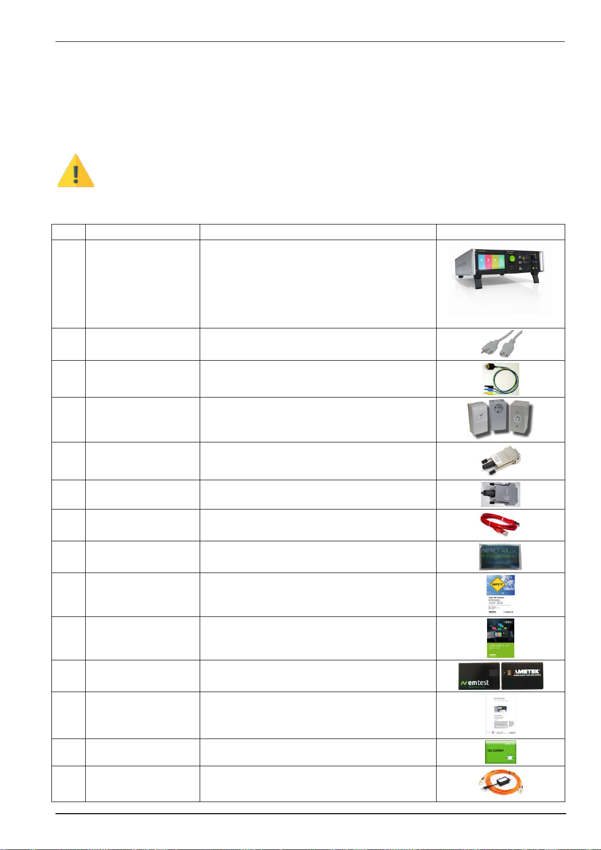
Using the following list, check that all the items ordered have been delivered:
Item
Name
Remark
Picture
1
Compaxt NX5
Compact NX5 generator including
- Single phase coupling network 300 V / 16 A
Including ordered Modules
- Burst Module
- Surge Module
- Power Fail Module
- Telecom Surge Module
2
Power Mains cable
Power Mains cable
- Connectors country coded
3
ESC
EUT Supply Cable
- Connectors country coded
4
ESA1
EUT Supply Adapter
- Connectors country coded
5
SCC AD
Safety Circuit Adapter (Sys. Link)
Short circuit for Interlock
6
SWL AD
Warning Lamp Adapter
7
Ethernet cable
Ethernet crossover network cable
RJ45, Cat 6, SF/UTP, red
8
Cleaning tissue
9
Safety Manual
Safety Manual
200 / 500 /NX Series
10
Quick Start Guide
Quick Start Guide
Compaxt NX –English or German
11
USB Memory card
Files on USB Memory card
12
User Manual
User manual (pdf on the memory card)
13
Iec.control Software
Software iec.control, (on the memory card)
14
Software license
If ordered on a license sheet
- UOC Optolink Converter USB to LWL
- Optical fiber cable 5m
EM TEST Compact NX5
Operating Manual V 1.06 13 / 143
3.2.2.
Accessories
If additional equipment is ordered refer to the user manual of these devices
Name
Remark
Picture
SLC xxx
Sys Link Cable with various cable length
UOC
USB Optolink Converter (USB to LWL)
Optical Fiber cable, 5m
Remark:
The USB Optolink is included in the software license
Copper braid
Earh band connection NX-generator to coupling NX,
Dimension: 300 x 23 mm, 25mm2, 4 x Screws M4 x 10mm
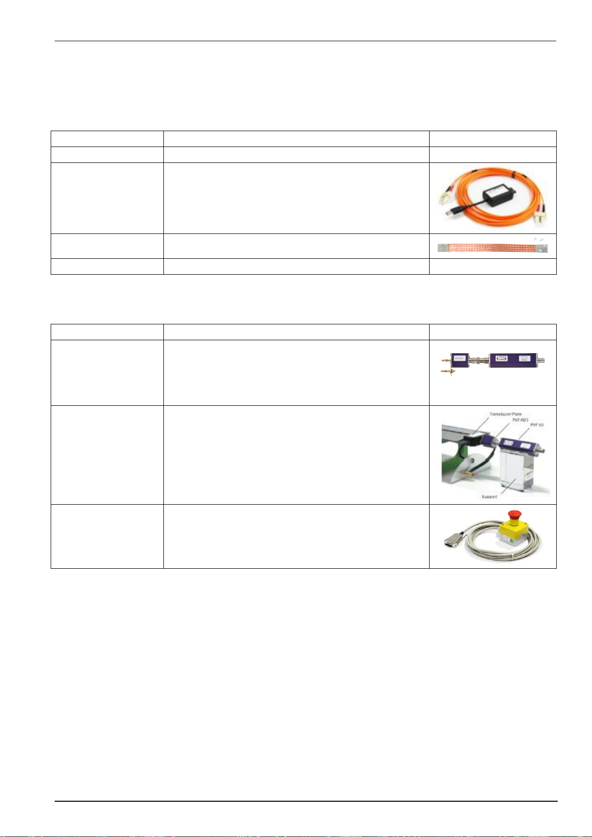
3.2.3.
Options
Name
Remark
Picture
PVF BKIT 1
Pulse Verification Fast Burst Kit 1
PVF 50, Pulse Verification Fast 50 Ohm
PVF 1000, Pulse Verification Fast 1000 Ohm
PVF AD 1 Pulse Verification Fast Adapter 1 –
Multi Contact (MC) to SHV fix
PVF AD1 PVF 50 or
PVF 1000
ICC PVKIT 1
Industrial Capacitive Coupling Clamp
Pulse Verification Kit 1
Transducer plate
Support
PVF AD3 Pulse Verification Fast Adapter 3 –
MC to SHF
ESS 1
ESS 1 Interlock for NX5 system
Switches OFF High voltage and EUT power supply
EM TEST Compact NX5
Operating Manual V 1.06 14 / 143
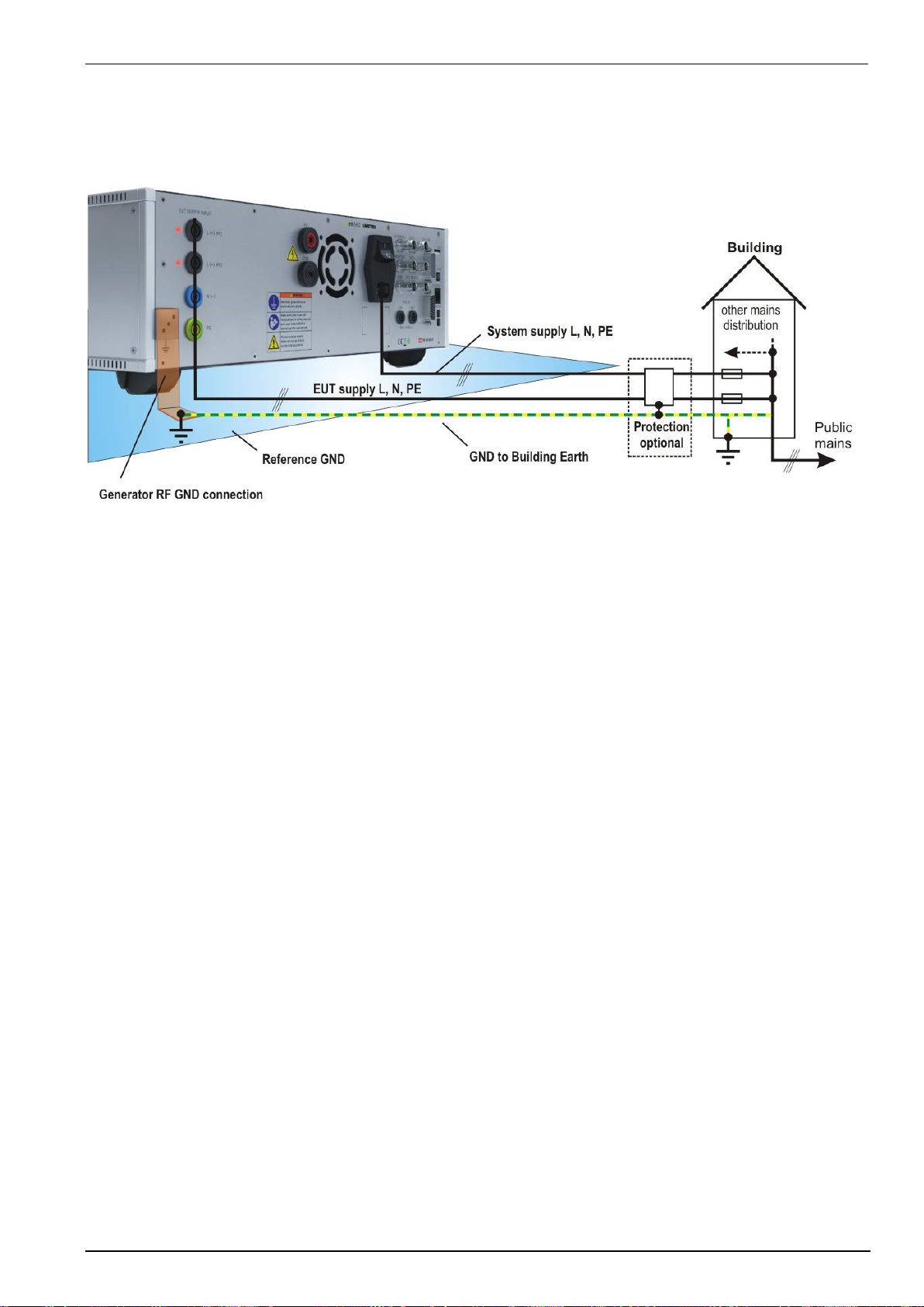
3.2.4.
Grounding and power connection
Two independent ground connections are necessary- one for the test system and one for the EUT. These must
be connected back to the local permanent installation or to a fixed, permanent ground conductor. To avoid
electric shock the power cord protective grounding conductor must be connected to ground.
System GND
The system is connected to GND via the earth wire of the connected mains power cable for the generator and the
EUT supply. A separate GND wire from the reference GND plane to the building earth point may be useful to
avoid interferences to other areas.
EUT GND
Ensure that a reliable return path for the interference current is provided between the EUT and the generator.
The GND wire from the generator to the reference GND and must be designed as a low inductance connection
suitable for high frequencies. The reference ground plane and the ground connections to the instruments, as
described in the relevant test standards, serve this purpose well.
Protection (optional)
A proposal is to separate protection of the EMC system with filters, insulation transformer or fault current
protection and other measures may be useful for the EMC installation. The advantage is the separation of the
EMC system from all other installation.
A shielded room with adequate filters may be the best solution for avoid unwanted conducted and radiated
interference to other areas.
EM TEST Compact NX5
Operating Manual V 1.06 15 / 143
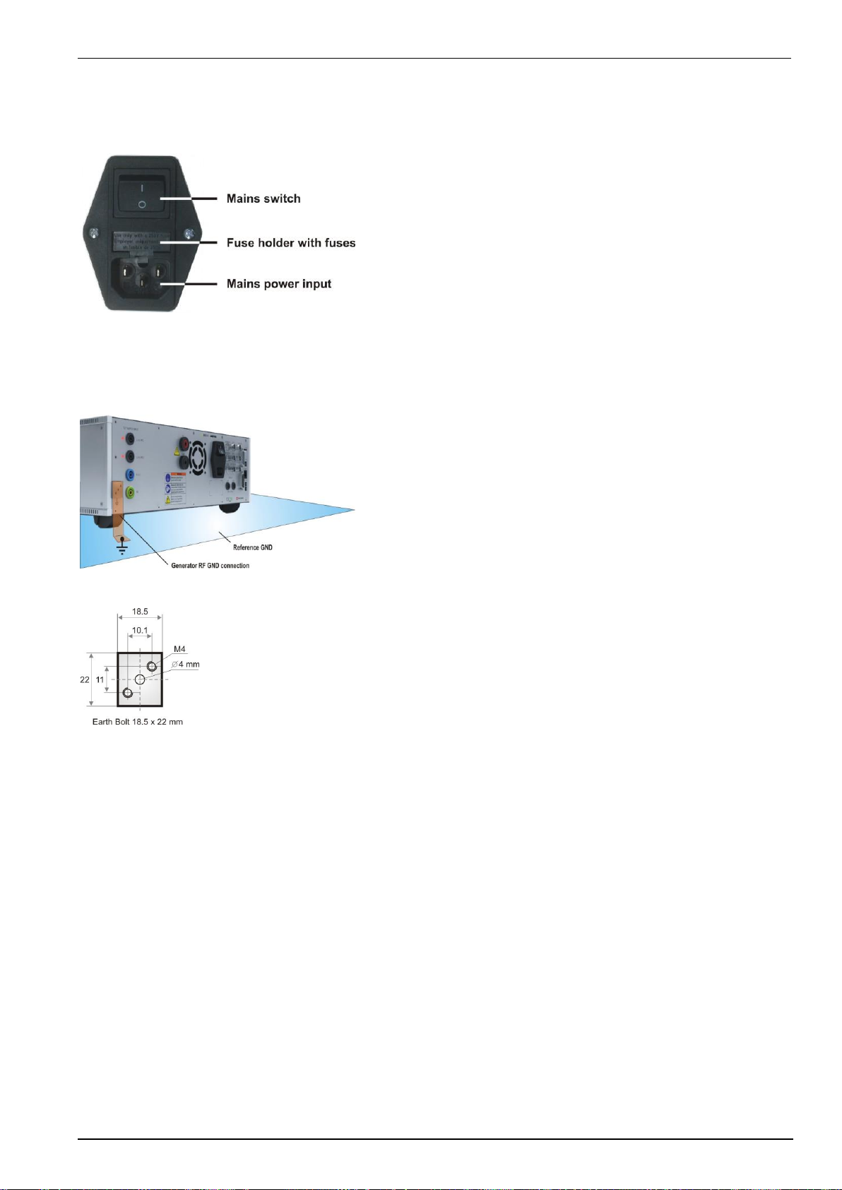
3.2.5.
Mains Switch and fuse
The mains power voltage indicated on the instrument must correspond with the local supply voltage (mains
voltage: 85–265 Vac, universal power unit, mains frequency: 50–60 Hz).
Mains Switch, fuse holder and power input
To replace a fuse:
1) Disconnect the mains cable
2) Pull the fuse holder out of the connector
3) Remove the damaged fuse(s)
4) Insert 1 or 2 fuses (4 A / 115V and 2 A / 230 V slow blow)
5) Replace the fuse holder
6) Plug the mains cable into a power outlet with a solid ground
connection
7) Switch the system on and operate as instructed in this manual
3.2.6.
Connecting the compact NX5 system to the ground reference
Connection to reference ground
Connection to reference ground
For burst tests, the generator must be placed on a ground
reference plane which is connected to ground.
A low inductive high frequency ground connection between the
test system and the ground reference plane (GRP) is absolutely
essential for performing burst tests correctly.
Earth bolt dimension
Earth bolt dimensions:
Screws: Metric M4 ,
Distance: 10.1 mm x 11 mm
Plug: Banana plug, 4 mm
EM TEST Compact NX5
Operating Manual V 1.06 16 / 143
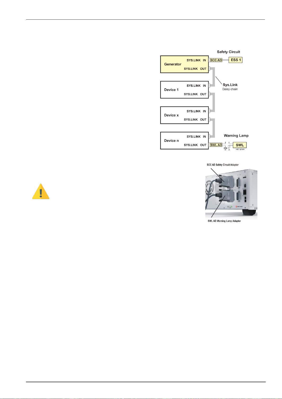
3.3.
Safety circuit, Warning lamps
Safety circuit and warning lamps are located at each end of the Sys Link. Each End of the Sys.Link is terminated
with an adapter.
Safety circuit
Plug position: SYS.LINK IN Compact NX generator
Connector: 2 screw contacts IN, OUT
Pin Sys Link: 7, 16
Operating: short circuit closed = operation
short circuit open = no operation
Voltage level: 24 Vdc (internal powered)
Warning Lamp
Plug position: SYS.LINK OUT Last device from daisy chain
Connector: 2 screw contacts IN, OUT
Pin Sys Link: 8, 17
Operating: Potential free contact
open = System is out of operation (green)
closed = System is operating (red)
Voltage level: 60 V, max. 2 A (external powered)
IMPORTANT
Important for operation
Connect the delivered Safety Circuit adapter SCC AD to
the SYSLINK plug.
The compact NX generator does not start any test if the safety
circuit is not connected and closed.
NOTE: The short circuit is already short-circuited at the
delivered Safety circuit adapter SCC AD.

EM TEST Compact NX5
Operating Manual V 1.06 17 / 143
3.3.1.
Safety circuit
The safety circuit locks the system and enables the
generation of the high voltage impulses in the
generators.
Design
Each device that has internal relevant high voltage
unit, includes a safety circuit. The safety circuit works
like an “open collector circuit”, where the external
safety loop must be closed for switch on the high
voltage.
Safety circuit closed
The device will generate high voltage pulses after start
Safety circuit open
The device will switch off the high voltage and
discharges the high voltage circuit
3.3.2.
Warning Lamp
The warning lamp offers a voltage free contact that
indicates the status of the generator system.
Design
Each device with warning lamp function can short
thewarning lamp contact. An external powered relays
max. 60 V / 2 A controls the lamp. The user is
responsible for the warning lamp power supply
Warning Lamp switch closed (red):
- Safety circuit is closed and
- TEST ON is on
Status:RED Lamp, Power on EUT output,
High voltage can be “ switched ON”
Warning Lamp switch opened (green):
- Safety circuit is open and / or
- TEST ON is off
- Generator is switched off
Status:GREEN Lamp, no danger, High voltage is off
EM TEST Compact NX5
Operating Manual V 1.06 18 / 143
3.4.
EUT Power supply and power switch
The EUT input should be connected through a properly rated power switch device, which should be located close
to the test setup. In order to ensure easy and quick access to the EUT power, the switch should be clearly and
visibly labeled as “EUT power ON/OFF”.
The in-house power distribution must be equipped with a proper circuit breaker and an emergency off button as
per IEC 61010-1:2001.
Dimensioning of the mains supply and rating of fuse protection of the AC or DC power supply must conform with
local electrical codes and EUT requirements. Inappropriate arrangement, mounting, cabling or handling of the
EUT or ground can reduce or negate the effectiveness of the compact NX5’s safety features.
3.4.1.
Notes on protective devices which need to install the operator
There are two different protective devices in a mains distribution system for safe operation.
A Fault current protection: A residual-current device (RCD), or residual-current circuit breaker (RCCB)
is an electrical wiring device that disconnects a circuit whenever it detects that
the electric current is not balanced between line and the return neutral. In
normal circumstances, these two wires are balanced, and any difference
current usually indicates a short circuit or other electrical anomaly like a surge
impulse is present.
B Circuit breaker protection: A circuit breaker is an electrical switch designed to protect an electrical
circuit by overload or short circuit. Its basic function is to detect a fault
condition and interrupt current flow.
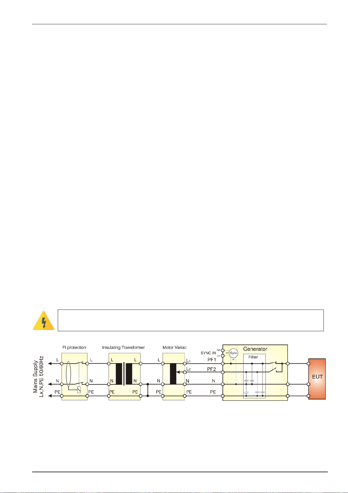
3.4.1.1.
Fault current protection
The standards recommend decoupling and filter capacitors to PE for decoupling surge pulses. This is the reason
for tripping fault current protection relays that interrupt the mains to the EUT supply. For eliminate the
circumstance use one of the following options:
Remove the fault current protection
This solution does not limit the current to PE. The surge test as other EMC tests with higher currents to PE are
possible. The user must take care to the circuit with no fault current protection. Only trained professional people
are allowed to perform such tests. Some countries do not allow to operate without fault current protection.
Using of insulating transformers
An insulating transformer separates the circuit from the test circuit. The Fault current detector (FI protection)
cannot detect the earth current in the EUT circuit.
The fault current safety detection function in the generator circuit is disabled. The user must respect
this circumstance. For a safe operation he must follow the electrical rulers.
Behind the insulating transformer the neutral and PE must be connected for a proper phase synchronization of
the generator. In case of a 3-phase system the user must perform similar.

EM TEST Compact NX5
Operating Manual V 1.06 19 / 143
3.4.1.2.
Fuses for EUT with smaller nominal currents
The EM Test pulse generators have no built in fuse for the EUT power supply. It is in the scope of responsibility
of the user to protect the EUT external for the rated current.
The design of the external fuse must be match the following rules:
- fuse dimension must be equal or smaller than the rated EUT current of the connected test
generator
- fuse must be designed for protect the connected EUT device under test in malfunction
Example of external circuit breaker
Circuit breakers in the building are designed for 32 A. A circuit breaker box with 16 A protection is
installed between the building supply and the test generator.
Test generator and EUT are now fused for 16 A rated current

EM TEST Compact NX5
Operating Manual V 1.06 20 / 143
3.4.1.3.
Phase indicator
The phase indication shows the correct connection of the supply to Phase and Neutral input of the compact
NX5. For the generator hardware both, L and N paths are potential free and a reverse connection is not relevant
for the generator operation.
For EUT where it is important that phase and neutral are correct, the LED indication shows the correct phase
connection.
Phase indication
1 compact NX5 generator
2 EUT supply may be a
- direct supply from building or via a
- tapped or variac transformer
3 Phase indication LED illuminated
4 Phase indication LED inactive
Remark: The phase synchronization signal taken
from the L path.
The table below shows all combinations with correct (OK) and incorrect (Fail) supply connections
Type A
Supply to PF1, L, PE
Type B
Supply to PF1, PF2, L, PE
Type C
Supply to PF2, L, PE
This manual suits for next models
7
Table of contents
Other EMTEST Laboratory Equipment manuals


Popular Laboratory Equipment manuals by other brands

VWR
VWR Powerpette Pro instruction manual

Owen Mumford
Owen Mumford Autoject 2 Instructions for use

vitro
vitro MD STAINER QUICK GUIDE TO TECHNICAL INSTRUCTIONS FOR USE AND CLEANING

Agilent Technologies
Agilent Technologies N2727A installation guide

Agilent Technologies
Agilent Technologies Intuvo 900 Safety manual

WEPA
WEPA TopiTec Automatic operating manual


