EMTEST CWS 500D User manual

Manual
for Operation
Continuous Wave Simulator
Type CWS 500D
Compact RF simulator for BCI, Stripline and TEM cell
applications. 10kHz – 400MHz ( 1000MHz)
The CWS500D is the state of the art solution in a
compact one-box design to test immunity to
conducted disturbances induced by radio frequency
fields. The CWS500D includes signal generator, RF
amplifier directional coupler, 3 channel power meter,
software and GPIB interface.
The integrated amplifier can also be controlled by an
external signal generators. ICD software supports the
test routines and controls external measuring
devices.
C
•ISO 11452 part 4
•ISO 11452 part 5
•RTCA DO 160D
•Mil 461 CS 114
•EN/IEC 61000-4-6
•various automotive
manufacturer’s
specifications
Version: 1.07 / 18.01.2007
emc test equipment Replaces: 1.06 / 28.06.2006
Filename: manual CWS500D V107.doc
Printdate: 18.01.07

EM Test CWS500 D
User manual V 1.07 2 / 34
Contents
1. Safety Aspects ..........................................................................................................................................3
2. Setup the CWS 500D ................................................................................................................................3
2.1. Connections CWS 500D ...........................................................................................................................3
2.2. Test Setup CWS 500D..............................................................................................................................3
2.3. Part Identifications and Functions.............................................................................................................4
2.3.1. Clamp Applications for Automotive standards ..........................................................................................4
2.3.2. CDN Applications as per IEC 61000-4-6 ..................................................................................................5
3. Operating Functions.................................................................................................................................6
3.1. Front View .................................................................................................................................................6
3.2. Rear view CWS 500D 400MHz model......................................................................................................7
3.3. Rear view CWS 500D 1GHz model ..........................................................................................................8
4. Front Panel Operation ..............................................................................................................................9
4.1. Basic Operations.......................................................................................................................................9
4.2. Quickstart ................................................................................................................................................10
4.2.1. Quickstart during instrument calibration..................................................................................................11
4.3. Display during Remote control ................................................................................................................12
4.3.1. Modulation...............................................................................................................................................13
4.4. Service ....................................................................................................................................................14
4.4.1. Adresses .................................................................................................................................................14
4.4.2. Setup .......................................................................................................................................................15
4.4.3. Amplifier Switch.......................................................................................................................................15
5. Starting Operation ..................................................................................................................................16
5.1. Safety Aspects ........................................................................................................................................16
5.2. Generator Function Check ......................................................................................................................17
5.3. Function Check internal Powermeter......................................................................................................18
5.4. Function Check amplifier switch ( 1GHz model only) .............................................................................19
5.5. Calibration ...............................................................................................................................................20
5.5.1. Calibration Setup for Bulk Current Injection Clamp (BCI) as per ISO / DO / MIL ...................................20
5.5.2. Calibration Setup EM TEST and IEC 61000-4-6 ....................................................................................21
5.5.3. Calibration Setup with CDN ....................................................................................................................22
5.5.4. Calibration Setup with EM Clamp ...........................................................................................................23
5.6. Failure Input ............................................................................................................................................23
6. Test Equipment CWS 500D....................................................................................................................24
6.1. Control Unit .............................................................................................................................................25
6.2. Generator Unit.........................................................................................................................................25
6.3. High frequency Power Unit .....................................................................................................................25
6.4. 3dB Attenuator ........................................................................................................................................25
6.5. CDN Coupling/ Decoupling Network.......................................................................................................26
6.6. Test Setup with CDN’s ............................................................................................................................27
6.7. Test Setup with the Current Monitor .......................................................................................................28
6.8. Test Level and Modulation ......................................................................................................................28
7. Technical Data.........................................................................................................................................29
8. Maintenance ............................................................................................................................................31
8.1. General....................................................................................................................................................31
8.2. Calibration and verification......................................................................................................................31
8.2.1. Factory calibration ...................................................................................................................................31
8.2.2. Guideline to determine the calibration period of EM Test instrumentation .............................................31
8.2.3. Calibration of Accessories made by passive components only: .............................................................31
8.2.4. Periodically In-house verification.............................................................................................................31
9. Delivery Groups ......................................................................................................................................32
9.1. Basic equipment......................................................................................................................................32
9.2. Options and Accessories ........................................................................................................................32
10. Appendix..................................................................................................................................................33
10.1. Blockdiagram ..........................................................................................................................................33
10.2. Declaration CE- Conformity ....................................................................................................................34

EM Test CWS500 D
User manual V 1.07 3 / 34
1. Safety Aspects
+
Before using the CWS 500 D read the following manuals carefully :
- Safety requirements manual
- Manual for operation CWS 500D
2. Setup the CWS 500D
2.1. Connections CWS 500D
Below are all possible connections to the CWS 500D
400MHz model figure 2.1
1000MHz model figure 2.2
Fig 2.1 : CWS 500D (400MHz) connection rear view Fig 2.2 : CWS 500D ( 1 GHz) connection rear view
2.2. Test Setup CWS 500D
Figure 2.3a / 2.3b :
Typical test setup with
required parts for BCI
application with CWS
500D
EM Test CWS500 D
User manual V 1.07 4 / 34
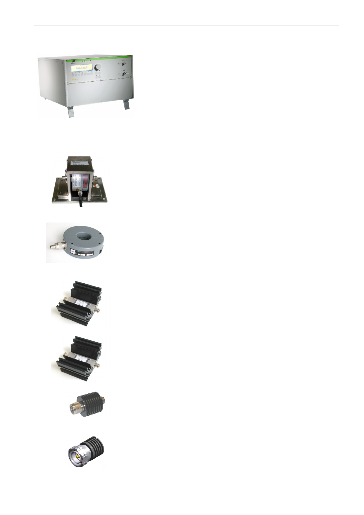
2.3. Part Identifications and Functions
Continuous Wave Simulator CWS 500D 400MHz
CWS 500D 1GHz
Fig 2.4
2.3.1. Clamp Applications for Automotive standards
Fig 2.5
Bulk Current Injection Clamp BCI type ( selection of clamps)
F-130-A1 10kHz – 400MHz
F-120- 6A 10kHz – 400MHz
FCC-BCICF-1 Calibration Fixture for BCI clamp (jig)
F-140A 100kHz - 1000 MHz
FCC-BCICF-2 Calibration Fixture for BCI clamp (jig)
Fig 2.6
Current Monitor Probe
F-33-2 1kHz – 250MHz
F- 55 10kHz – 500MHz
F- 65 100kHz - 1GHz
Fig 2.7
Attenuator 3dB optional
Type ATT3/100
3dB 100W
Fig 2.8
Attenuator 20dB ( for DO and MIL application )
Type ATT20/100
20dB 100W
Fig 2.9
Attenuator 20dB
20dB 15W
Fig 2.10
Terminating resistor 50 Ohm optional
50 Ω6W

EM Test CWS500 D
User manual V 1.07 5 / 34
2.3.2. CDN Applications as per IEC 61000-4-6
Fig 2.11
Bulk Current Injection Clamp BCI type
F-120-9A 10kHz – 230MHz
FCC-BCICF-4 Calibration Fixture for BCI clamp (jig)
Fig 2.12
Attenuator 6 dB / 75W
Fig 2.13
Coupling / Decoupling Network
Types:
CDN-M 1; M 2; M 3; M4; M 5;
CDN-S1-50/75Ω; S 2; S 4; S 9; S 15; S 25; S68
CDN-T 2; T 4; T 2-RJ11; T8-RJ45;
CDN-AF 2; AF 3; AF 4; AF 8
Fig 2.14
EM Clamp
Type EM 101
Fig 2.15
Calibration
CWS-Cal Basic Calibration Kit
Transport Case
150Ωto 50ΩAdapter
BNC cable 0.5m
Cal adapter according to CDN ,
Fig 2.16
Adapter
R100 150Ωto 50ΩAdapter
R100A 150Ωto 50ΩAdapter for Current Clamp CAL Fixture
EM Test CWS500 D
User manual V 1.07 6 / 34
3. Operating Functions
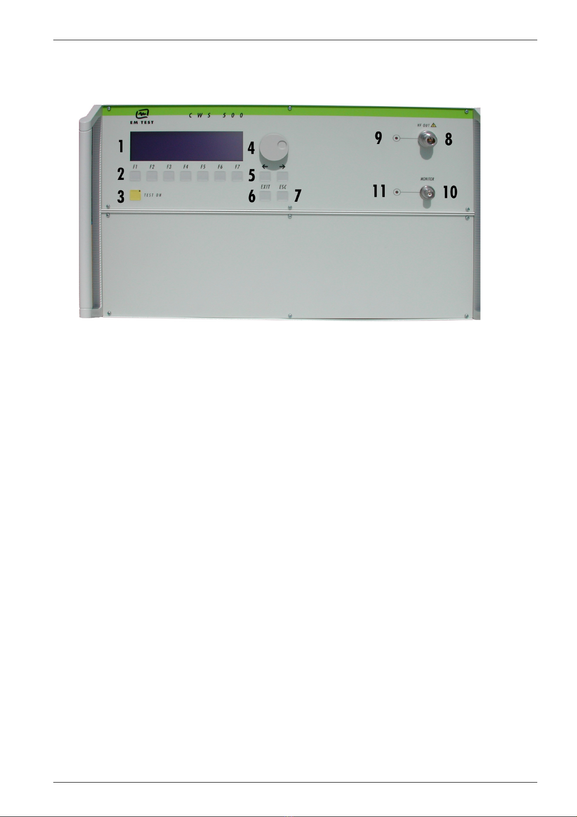
3.1. Front View
Fig 3.1
1. Display
2. Function keys "F1..F7"
3. "Test On"
4. Knob (Inc / Dec)
5. Cursor keys "←" and "→"
6. Exit
7. Escape
8. RF Output
9. LED RF Output Monitor
10. Current Probe Input (Monitor)
11 LED Current Probe Input
1Display
All functions and parameters are displayed (8 lines with max. 40 characters).
2 Function Keys "F1 .. F7"
Parameters and functions displayed in the lowest line and functions displayed with ” F “, can be selected
with the related function key.
3 Test On
By pressing the key "TEST ON", the RF signal will be released and the test procedure can be started.
4 Knob (Inc / Dec)
This knob increments or decrements parameters with a numeric value or selects parameters from a list.
5CursorKey
Parameters and functions can be changed during the test. The selection of these parameters is done with
the cursor, moving it to the left or to the right.
6 EXIT
The EXIT button resets the firmware to the main menu. This is only possible, if no test routine is running.
7 ESC
The ESC button returns back to the previous level in the menu.
8 RF-Output
At this output the RF power is available. The 3dB-attenuator is connected, if available, via coaxial cable.
For conducted tests together with CDN’s, EM clamps or current injection clamps, it may be suggested to
load the simulator with a matched 50 ohm load. In case the above mentioned coupling device may not
represent such matched load, then it is recommended to add a 3dB attenuator in between.
9 LED RF Output Monitor
When the RF output is active this LED on the front panel is illuminated to indicate that a test signal is
generated.
10 Current Probe Input
For tests with a current injection clamp where the EUT current has to be measured and/or monitored, the
current probe can be connected to this input.
ATTENTION: Do not connect the RF output directly to this input otherwise it will be damaged.
11 LED Current Probe Input
EM Test CWS500 D
User manual V 1.07 7 / 34
When current monitoring is active this LED on the front panel is illuminated.
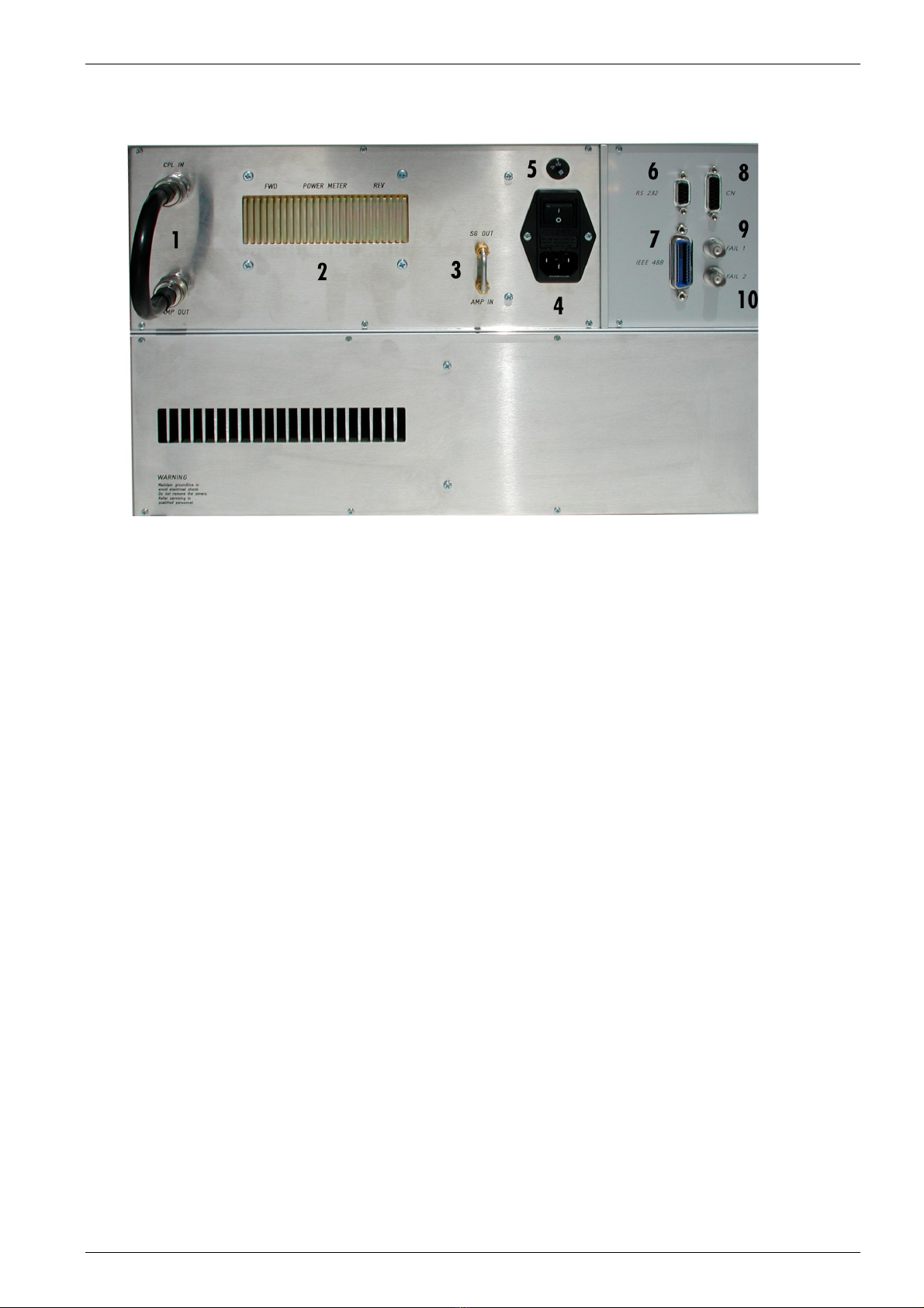
3.2. Rear view CWS 500D 400MHz model
Fig 3.2
1 Connection Amplifier OUT to Coupling IN
2 Bi-directional coupler
3 Connection Signal Generator to Amplifier
4 Power On Switch
5 Power selector 115V – 230V
6Serial Interface RS 232
7IEEE Interface
8 Remote Control Connector
9 Fail 1 Detection "Stop"
10 Fail 2 Detection "Pause"
1 Connection Amplifier OUT to Coupling IN
This connection link is between the amplifier and the power measurement device to the RF Output at the
front side. The user has the possibility to connect the amplifier to another device like a TEM cell.
2 Bi- directional coupler
3 Amp In / SG Out
The internal amplifier can be controlled by an external signal generator. For this operation, the short circuit
link must be disconnected. The external signal generator must be plugged into the connector “Amp In”.
4 Power On Switch
The switch and the main fuses are part of this box. (230V / 3.15AT or 115V / 6.3AT)
5 Power selector
Input power selector for input voltage 115V – 230V.
6 Serial Interface
RS 232 interface with 9-pin connector.
7 Parallel Interface IEEE
IEEE 488 interface with IEEE connector.
8 Remote Control Connector
not used.
9 Fail Detection FAIL 1 (TEST STOP)
The BNC input FAIL 1 can be used for failure detection on the EUT. If the input is set to ground (chassis),
the CWS 500D generator will be stopped and finish the test routine. It is not possible to continue the test.
A complete restart of the routine will be necessary. The message "FAIL 1" is indicated in the ICD software.
10 Fail Detection FAIL 2
The BNC input FAIL 2 can be used for failure detection on the EUT. If the input is set to ground (chassis),
the failure will be detected and the test continues normally. After a FAIL 2 events the test routine will stop
and the message ”FAIL 2“ will appear in the host screen ( ICD software).

EM Test CWS500 D
User manual V 1.07 8 / 34
3.3. Rear view CWS 500D 1GHz model
Fig 3.3
1 Connection Ext. Amplifier RETURN
2 Pre coupler insert loop
3 SG out
4 Power On Switch
5 Power selector 115V – 230V
6 Serial Interface RS 232
7 IEEE Interface
8 Remote Control Connector
9 Fail 1 Detection "Stop"
10 Fail 2 Detection "Pause"
1 Connector External Amplifier (EXT AMP Return )
Input signal from an external amplifier. ( max. power 200W)
2 Pre Coupler insert loop
Output and return connection for the external device like a filter or TEM cell
3 SG Out
Output to an external amplifier for control an amplifier >100W .
4 Power On Switch
The switch and the main fuses are part of this box. (230V / 3.15AT or 115V / 6.3AT)
5 Power selector
Input power selector for input voltage 115V – 230V.
6 Serial Interface
RS 232 interface with 9-pin connector.
7 Parallel Interface IEEE
IEEE 488 interface with IEEE connector.
8 Remote Control Connector
not used.
9 Fail Detection FAIL 1 (TEST STOP)
The BNC input FAIL 1 can be used for failure detection on the EUT. If the input is set to ground (chassis),
the CWS 500D generator will be stopped and finish the test routine. It is not possible to continue the test.
A complete restart of the routine will be necessary. The message "FAIL 1" is indicated in the ICD software.
10 Fail Detection FAIL 2
The BNC input FAIL 2 can be used for failure detection on the EUT. If the input is set to ground (chassis),
the failure will be detected and the test continues normally. After a FAIL 2 events the test routine will stop
and the message ”FAIL 2“ will appear in the host screen ( ICD software).
EM Test CWS500 D
User manual V 1.07 9 / 34
4. Front Panel Operation
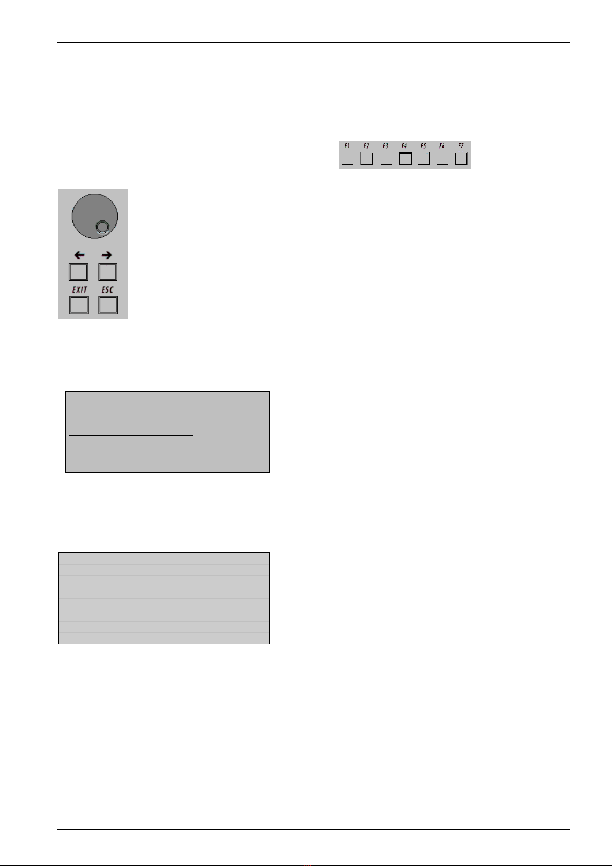
4.1. Basic Operations
The simulator is operated by an easy menu control system.
Seven function keys are available to select parameters and
functions. Fig 4.1
The selected parameter is blinking and can be changed by turning the knob (incr./decr.).
ÍÎ : The digit to be changed can be selected with the cursor (ÍÎ ).
- Setted values are direct indicated on the screen.
- Status on the bottom lines shows the desired status after pressing the function
key.
ESC : ESC will take you back to the previous level in the menu and set the displayed
values. The latest settings are stored automatically and will be recalled when the
menu is selected again.
EXIT : The firmware will reset to the main screen.
Fig 4.2
Start-up display
EM TEST
C W S 5 0 0D
RF 9kHz – 1 GHz
V 2.11a03 SWN: 002234
←Generator Model
←Frequency Range
The version number and the software number SWN are used for tracing purposes. These numbers are listed in
the test reports and calibration certificates. These numbers are also listed within the test reports generated by
the software report generator.
Page 1 (Main Menu)
MAIN MENU
F1 : Quickstart
F7 : Service
F1 F2 F3 F4 F5 F6 F7
F1 Quickstart
Manual operation by entering the attenuation, frequency and modulation
F7 Service
Setup can be selected and displayed

EM Test CWS500 D
User manual V 1.07 10 / 34
4.2. Quickstart
Easy and very fast operation for functions check and verification of the CWS 500D.
Page 2 (Show Parameters) Page 3 (Change)
Quickstart Quickstart
Att = 63,0 dB f = 109.500 MHz
Mod = AM 1kHz 80% Att : 0.0 dB - 63.5 dB
f : 0.009 MHz - 400.0 MHz
Mod : OFF, AM 80%, AM 90%, Pulse
Att f Mod
START CHANGE 57.0 109.5 ON
F1 F2 F3 F4 F5 F6 F7 F1 F2 F3 F4 F5 F6 F7
Press START to begin testing.
Press CHANGE and the actual parameters can be changed. Selecting a parameter to change will display the
range.
The test begins by pressing START. The blinking parameter can be changed with the knob inc./dec.
Use the cursor keys (ÍÎ ) to select other parameters. By pressing STOP the test will be stopped and on the
last line of the display it will be indicated that the test has been stopped.
Page 3 (Operating)
Quickstart
Att = 33,0 dB f = 109.500 MHz
Mod = AM 1kHz 80%
FPow = - 9.7 dBm Mon = -56.9 dBm
Rpow = - 16.5 dBm
STOP
F1 F2 F3 F4 F5 F6 F7
Error messages:
Quickstart
Att = 40,0 dB f = 109.500 MHz
Mod = off
FPow = + 6.6 dBm Mon = -57.3 dBm
Rpow = + 6.8 dBm
Fpow to low !
Message : Fpow to low !
What happens : The amplifier does not supply the expected gain. The firmware checks the ratio between the
signal generator output and the Forward power. The reason can be an amplifier defect or an
internal error in the CWS 500D. This message appears only when using internal amplifier.

EM Test CWS500 D
User manual V 1.07 11 / 34
4.2.1. Quickstart during instrument calibration
This function needs Firmware 2.11 or higher.
In case of a calibration of the measuring instrument it is necessary to use external signal generators. The CWS
instrument has frequency matched calibration curfes for each instrument channel. When using the internal
signal generator CWS 500 knows the actual frequency and select automatically the correct reference. When
using an external signal Generator, the instrument does not know the actual frequency. Therefore it is very
important to adjust the frequency in the display to the actual applied frequency. otherwise the displayed
measuring value can be wrong.
Page 3 (Operating)
Quickstart AMP :2
Att = 63,0 dB f = 100.000 MHz
Mod = AM 1kHz 80%
FPow = - 3.0 dBm Mon = -56.9 dBm
Rpow = - 56.5 dBm
-----------------------∆f---------------------
STOP 1k 10k 100k 1M 10M
F1 F2 F3 F4 F5 F6 F7
Adjust the frequency when using an external signal generator during instrument calibration
EM Test CWS500 D
User manual V 1.07 12 / 34
4.3. Display during Remote control
The CWS 500 can only work with remote control from the ICD software Version 3.00 or higher. During the
operation the following information appears on the display:
Remote control
R E M O T E ProgRemote
f = 5.420MHz Mod = OFF
FPow = -17.6 dBm
FPow = ----- dBm
Mon = -30.4 dBm Dwell Time 0.3s
During Remote operation the display shows different screens depend the actual software procedure
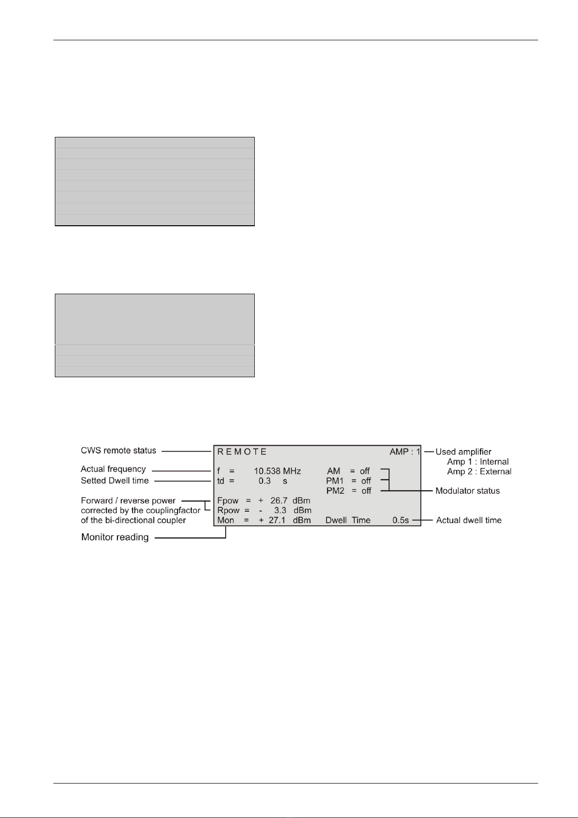
Waiting
R E M O T E AMP : 1
f = 10.538 MHz AM = off
td = 0.3 s PM1 = off
PM 2 = off
Display during a test

EM Test CWS500 D
User manual V 1.07 13 / 34
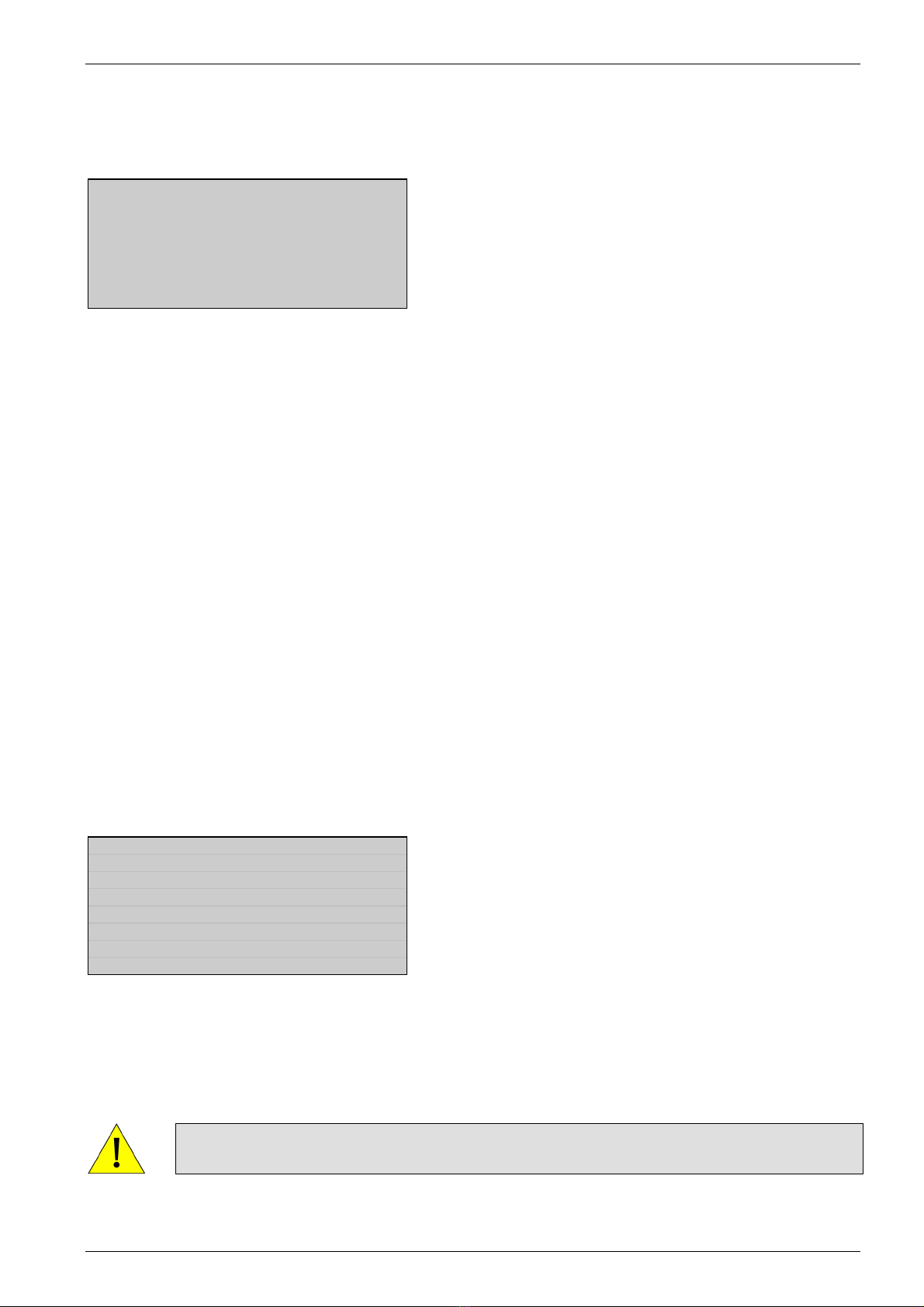
4.3.1. Modulation
Modulation as per IEC
Figure 4.3 shows the modulation for IEC
application.
Fig 4.3 : Unmodulated 80% AM Pulse modulation
Modulation as per ISO
Modulation signal as per ISO, peak
conservation ( pulse) standard. These
standards recommends the modulation signal
with the same amplitude as the non modulated
signal.
Fig 4.4 : AM modulation with peak conservation

EM Test CWS500 D
User manual V 1.07 14 / 34
4.4. Service
All service functions are indicated in the display.
Page 2 (Overview service)
SERVICE
F1 : Addresses
F3 : Setup
F4 : Amplifier Switch
F5 : Function check powermeter
F6 : Function check amplifier switch
F1 F2 F3 F4 F5 F6 F7
F1 Addresses
The addresses of EM TEST AG Switzerland and EM Test GmbH Germany will be displayed.
A list of the world-wide sales partners is awailable on the internet under www.emtest.com.
F3 Setup
The software will clearly explain the setup procedure.
F4 Amplifier Switch
Set the amplifier to internal / external.
Default setting after power on or go to local setting : internal
F5 Function check Powermeter
Function check routine for the built in powermeter (PM). With this check function the correct working of the PM
can be verified.
F6 Function check amplifier switch
Check function for verification of the correct working of the built in amplifier switch, and the built in Amplifier
( gain >50dB ).
4.4.1. Addresses
The addresses of the EM TEST AG and the
EM TEST GmbH are shown. The addresses of all EM
TEST sales agencies are listed on the web site of EM
Test under :
www.emtest.com
Page 3 (Addresses)
EM TEST AG Switzerland
Sternenhofstr. 15
CH – 4153 Reinach BL1
Tel : +041 61 717 91 91
Fax : +041 61 717 91 99
For further sales offices
CH D refer to www.emtest.com
F1 F2 F3 F4 F5 F6 F7
EM Test CWS500 D
User manual V 1.07 15 / 34
4.4.2. Setup
This menu helps the user to define the configuration of the CWS 500D.
Page 3 (Setup Overview)
Setup
F1 : Change language / Sprache ändern
F2 : LCD Back Lighting
F3 : Interfaces
F4 : Keyboard Beeper
F5 : Timer
F1 F2 F3 F4 F5 F6 F7
F1 Change language / Sprache ändern
The user can choose between two languages, German and English.
F2 LCD Back Lighting
With the use of F2 the back lighting can be switched ON or OFF. The Auto-Off Function can be programmed to
switch the back lighting off after a predetermined time following the last manual operation (1 - 30 minutes).
Due to the limited lifetime of the LCD back lighting (approx. 10,000 hours), this function should always be
activated.
The Auto ON/OFF function does not switch on during remote operating
F3 Interfaces
With this menu the user can define the status of the integrated serial and parallel interfaces, e.g. the baud rate
of the RS232- or the address of the IEEE-interface.
F4 Keyboard Beeper
F4 selects the beeper ON/OFF mode.
F5 Timer
By pressing F5 will display the total operating time of the CWS 500D will be displayed.
4.4.3. Amplifier Switch
Change of the used amplifier internal or external
Page 3 (Amplifier Switch)
Amplifier Switch
F1 : Amplifier Int / Ext
Int / Ext
Int
F1 F2 F3 F4 F5 F6 F7
The CWS display shows the actual setting for the used amplifier
Int : Internal = Amp 1
Ext : External = Amp 2
After power on the default amplifier is set to internal

EM Test CWS500 D
User manual V 1.07 16 / 34
5. Starting Operation
5.1. Safety Aspects
Tests performed with RF-disturbances, induced by radio-frequency fields, are immunity tests on electronic
equipment. Therefore it is the responsibility of the user to avoid critical failures and risks to the environment and
the operators.
Long power supply lines to the EUT may radiate energy. It is the responsibility of the user to determine whether
it is allowed to conduct immunity tests in a given location.
The RF voltages on the center pin of the RF output connector can be hazardous. The RF output connector must
be connected to a load before AC power is applied to the CWS 500D. Do not touch the center pin of the RF
output connector or accessories which are connected to it. Switch the equipment to the “Test OFF” position
before disconnecting or connecting the load to the RF output connector.
During this test RF interference is generated at a power of 100W or more. Therefore, the test should be
performed in a shielded room to prevent interference with other equipment in the vicinity. Also see the
information included in the declaration of conformity for the CE mark.
For the test setup, national and international safety regulations must be observed.
Persons beings with pacemakers must not be allowed to perform such tests.
Special Information For Operating the CWS 500D :
1. The intake and outlet for the cooling system must not be covered. Free air circulation of is required for
proper function of the CWS 500D. Blockage of the cooling air system may result in damage to the RF
amplifier or intermittent shut down of the equipment.
2. All panels must be installed. They are important components of the cooling system. Never perform tests
with a partially or completely open generator.
3. Before a test or a calibration may be performed, the CWS 500D must be operating for at least 15 minutes
warm up time. After this time the CWS 500D output becomes stable
4. High voltage components will only be exposed when the 3 cover panels are removed (unscrewed). To
service the inside the generator, the power supply must be turned off and the power cord must be removed
before opening the equipment.
5. CDN’s are coupling/decoupling networks as specified in IEC 61000-4-6 . Due to this specification, higher
ground current exists as a result of increased value of the Y-capacitors. Therefore, the general use of fault
current protection relays is not possible. The use of isolating transformers for the power supply may be
required.
6. Some CDN’s are designed for higher and hazardous voltages. It is necessary to remove the power cord
from the input connection of the CDN’s before opening the housing.
7. Only trained and qualified service technicians are allowed to perform service and repair the instruments.
Please contact an EM TEST service center or your local sales partner for repairing or servicing the units.
8. The calibration of the test setup has to be done on the output of the CDN’s. To connect the 150-to-50Ω
matching resistor, special adapters are required (e.g. power supply connector to single pole plugs).
9. Make sure to read carefully and completely all the manuals.
EM Test CWS500 D
User manual V 1.07 17 / 34
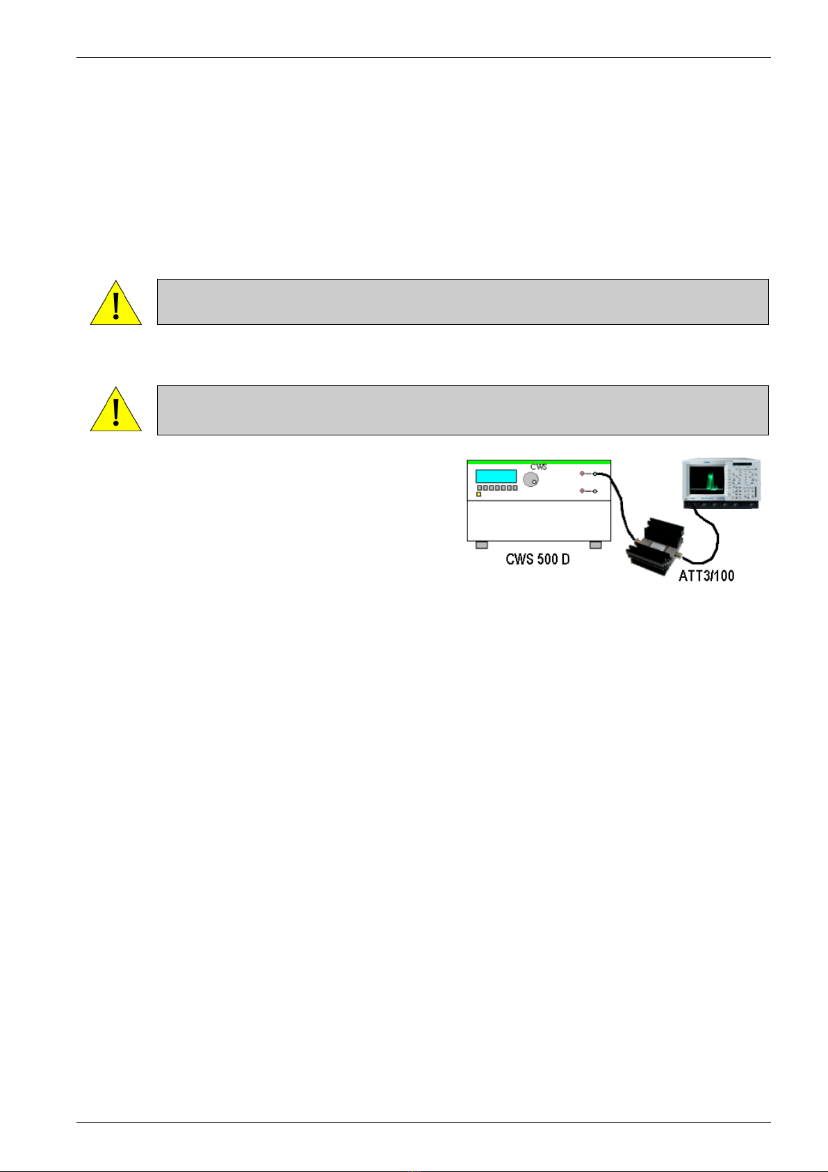
5.2. Generator Function Check
As with all testing equipment, the continuous wave simulator type CWS 500D should be checked for
performance and accuracy from time to time. The check should be completed as listed below.
- Connect the RF-output of the CWS 500D to the 3dB-attenuator or an adequate attenuator.
- Switch on the power supply.
- Select the in Quickstart with the following parameters:
voltage : 30dB
frequency : 23MHz
modulation : OFF, 2Hz, 400Hz or 1kHz
- Connect the output of the 3dB-attenuator with the 50Ωinput channel of the oscilloscope.
ATTENTION Take attention to the maximum input power capability and the bandwidth of the
test input.
- Push "TEST ON" and start the test.
ATTENTION DO NOT connect the output of the ATT3/100 nor the output of the CWS 500D
to the monitor input, otherwise the monitor input will be destroyed.
Using an oscilloscope or powermeter for checking the
operation of the generator very easy. Fig 5.1.
Take notice that this procedure is only a functional check of
the generator. Differences in the test level may be caused
by a limited bandwidth or mismatching within the testing
system.
Exact and accurate measurements can only be guaranteed
with the specified test setup according to standard. Fig 5.1
expected values >22 dBm
-30dBµA 53dB = 23dBm ±4dB

EM Test CWS500 D
User manual V 1.07 18 / 34
5.3. Function Check internal Powermeter
This function is for checking the built in 3-channel powermeter e.g. Forward Power and Rev Power and current
monitor. Within this measuring procedure the measured values are compared with some nominal values, this in
order to verify the correct function of the three measuring inputs. In addition also the accuracy of the measuring
is checked in a larger range. In order to avoid any damage, it may be self explaying that only a low voltage
signal may be released by the amplifier and occur at these inputs.
The MONITOR input is tested with the following signals:
- Measuring with a 50Ωterminal connection at the input.
- Measuring with the maximum attenuation ( -60dB ) to the RF output via a 3dB attenuator.
- Measuring with a reduced attenuation (-45dB ) to the RF output via a 3dB attenuator.
The function check has the following procedure:
Page 3 (Service )
Function check Powermeter step 1/ 2
- Press TEST ON
- Disconnect the HF OUT
- Connect a 50 Ohm matching resistor
to the MONITOR input
continue break Fig 5.2
F1 F2 F3 F4 F5 F6 F7
50 Ωmatching resistor
connected at the monitor
input.
Page 3 (Service )
Function check Powermeter step 2/ 2
- Connect the MONITOR input to the
HF OUT via a ATT 3 dB attenuator
continue break
Fig 5.3
F1 F2 F3 F4 F5 F6 F7
Page 3 (Service )
Function check Powermeter result
Pass / Fail
end
F1 F2 F3 F4 F5 F6 F7
Finally the result of the check appears in the display. With the measured results the user is able to check the
correct function of the measuring inputs.

EM Test CWS500 D
User manual V 1.07 19 / 34
5.4. Function Check amplifier switch ( 1GHz model only)
This function is for checking the correct operation of the built in amplifier switch. During this test the output
connector at the frontside should be left open.
The function check has the following procedure:
Page 3 (Service )
Function check amplifier switch
- Press TEST ON
- Disconnect the HF OUT
- Connect the SG OUT directly
to the CPL IN ( on the backside )
continue break Fig 5.4
F1 F2 F3 F4 F5 F6 F7
Page 3 (Service )
Function check amplifier switch
result
Pass / Fail
end
F1 F2 F3 F4 F5 F6 F7
EM Test CWS500 D
User manual V 1.07 20 / 34
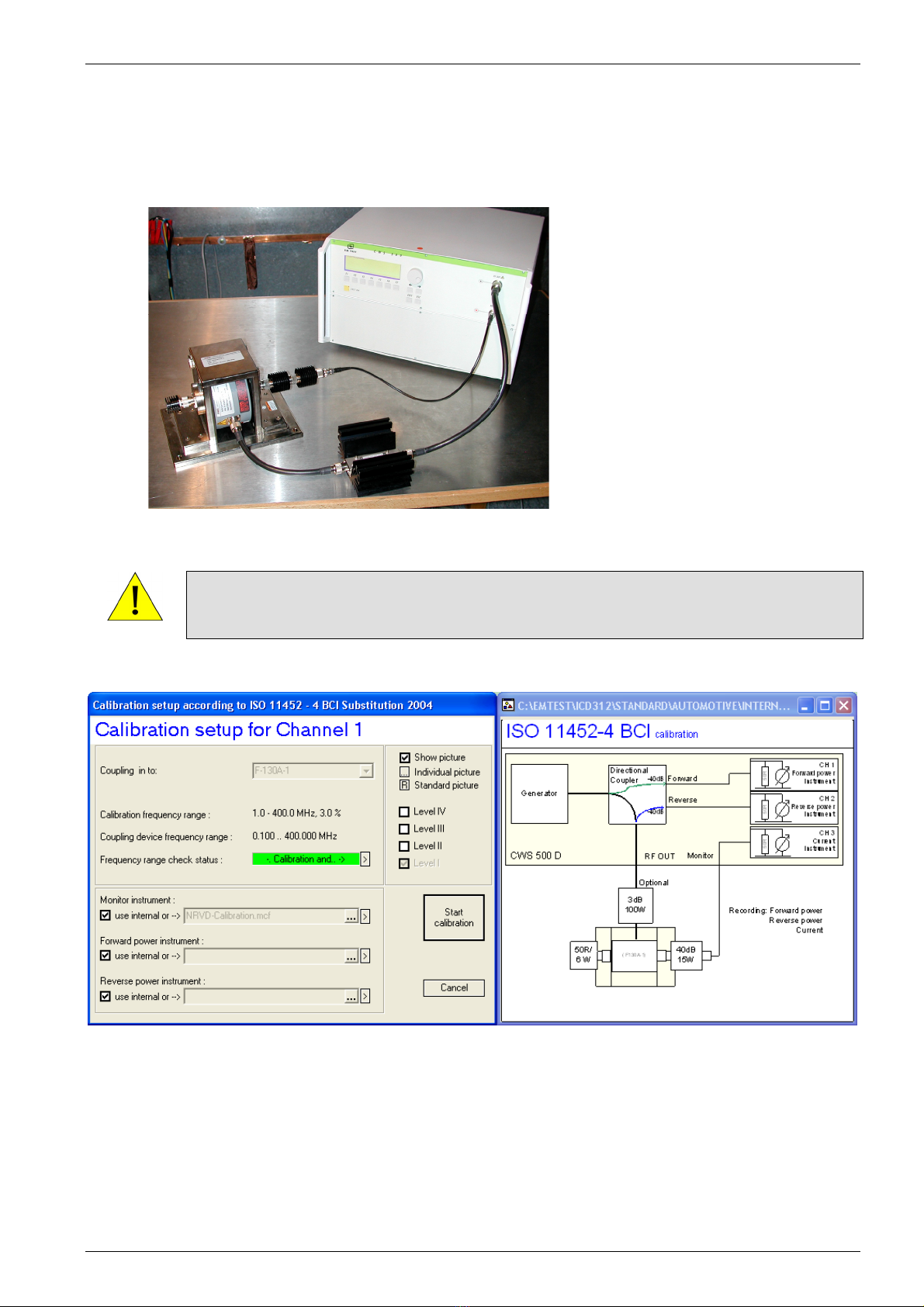
5.5. Calibration
5.5.1. Calibration Setup for Bulk Current Injection Clamp (BCI) as per ISO / DO / MIL
Fig 5.5 : Calibration setup with BCI
ATTENTION
During calibration of the test setup on a ground reference plane at very low levels (very low
currents) is important. The test results may be influenced by the cable layout on the ground
plane. High grade coaxial cables are essential.
Fig 5.6 : Calibration setup with BCI
Table of contents
Other EMTEST Laboratory Equipment manuals


Popular Laboratory Equipment manuals by other brands


Medic Therapeutics
Medic Therapeutics MT-UVWA-001 manual

Endress+Hauser
Endress+Hauser Liquistation CSF48 operating instructions

Monmouth Scientific
Monmouth Scientific Circulaire HLFT1000 operating & maintenance manual

Buchi
Buchi KjelDigester K-446 Operation manual

Millipore
Millipore Labscale user guide

Gilson
Gilson MyPIPETMAN Select manual


