DLab DM0506 User manual

Ver.20210717
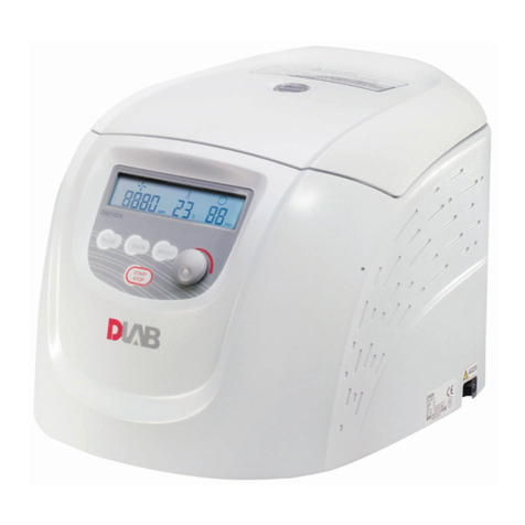
DM0506 Clinical Centrifuge
This user manual needs to be read before operating this product.
Please follow the safety instructions provided in this manual.

1
Table of Contents
Safety Warnings .................................................................................................................................. 1
1. Performance indicators............................................................................................................... 3
2. Conformity to standards ............................................................................................................. 3
3. Environmental requirements ...................................................................................................... 3
3.1. Basic operating requirements ................................................................................................. 3
3.2. Transport and storage conditions........................................................................................... 4
4. Installation................................................................................................................................... 4
4.1. Mounting position................................................................................................................... 4
4.2. Connection between power cable and ground wire............................................................... 4
5. Structure...................................................................................................................................... 5
6. Operating panel........................................................................................................................... 6
7. Rotor preparation........................................................................................................................ 7
7.1. Prepare the samples to be separated..................................................................................... 7
7.2. Place samples into the centrifuge tube................................................................................... 7
7.3. Ensure the balanced centrifuge tube...................................................................................... 7
7.4. Check the rotor........................................................................................................................ 7
7.5. Insert the centrifuge tubes symmetrically onto the rotor in place without imbalance.......... 8
8. Operation .................................................................................................................................... 8
8.1. Normal operation.................................................................................................................... 8
8.2. RCF operation........................................................................................................................ 11
8.3. Set deceleration level............................................................................................................ 11
9. Maintenance and servicing ....................................................................................................... 11
9.1. Cleaning................................................................................................................................. 11
10. Common failures and solutions................................................................................................. 12
10.1. List of common failures......................................................................................................... 12
10.2. How to open the outer lid..................................................................................................... 13
11. Introduction to rotor and centrifuge tube ................................................................................ 14
11.1. Rotor description................................................................................................................... 14
11.2. Centrifuge tube ..................................................................................................................... 16
2
12. RCF calculation .......................................................................................................................... 17
13. Warranty ................................................................................................................................... 18
13.1. Unit warranty ........................................................................................................................ 18
13.2. Rotor warranty...................................................................................................................... 18
14. After-sales services.................................................................................................................... 18

Safety Warnings
The symbol is an internationally accepted safety mark. Please carefully read and fully
understand the following safety rules:
⚫Comply with the operation requirements contained herein and ensure safe operation.
⚫Carefully read all safety information and reminders provided in this manual.
⚫Safety information is marked as follows. The safety symbol is combined with the “Warning”
and “Caution” respectively, reminding users of the potential danger. These two combinations and
the “reminder”symbols are defined as follows:
Warning: personal danger.
Warning against potential dangers, which might result in injury or death if the requirements contained
herein are not strictly complied.
Caution: Potential danger to instrument
Ensure to comply with all the safety requirements as mentioned to avoid potential dangers of damage
to the instrument
Reminder: matters that generally call for attention.
⚫Do not use this centrifuge in any manner not mentioned in this user manual.
⚫In case of any problem, please contact the vendor/supplier.
⚫This user manual provides complete details of the potential dangers, however users are advised
to stay alert against unpredictable circumstances and use this centrifuge with care.
Warning:
⚫This centrifuge is non-explosion proof and may not be used for separation of flammable or
explosive samples.
⚫Do not install this centrifuge in the vicinity of any flammable gas or chemical substances.
⚫Do not place anything that causes danger within 30cm radius of this centrifuge.
⚫Take appropriate safety measures before centrifugation of any toxic, radioactive or pathogenic
organisms. If the microorganism sample being centrifuged is secondary hazard (as defined in the
WHO’s “Laboratory Biosafety Manual”), ensure to use biological sealing devices.
⚫Ensure to sterilize it according to decontamination procedures that are mentioned under
sterilization section.
⚫If there is any need for onsite assistance, sterilize and decontaminate the centrifuge in advance and

notify the service representative about the details.
⚫Never touch the power cable/switch with wet hands and avoid electric shocks.
⚫As a safety measure, ensure to maintain at least 30cm distance from the centrifuge while in
operation.
⚫For safety reasons, when the centrifuge is running, the personnel should maintain a 30cm distance
from the centrifuge.
⚫Never open the lid while the rotor is in operation.
⚫The centrifuge should be opened for repair/ dismantling by trained staff only.
Caution
⚫Ensure that the centrifuge is stably placed on level and solid work bench before any operation.
⚫Ensure that the angle between the outer lid and housing is larger than 70° while opening the lid.
⚫Never place hands/any other things in between the outer lid and the housing.
⚫Don’t move or lean against the centrifuge if it is in operation mode.
⚫If there is any liquid found in the centrifuge, ensure to wipe it OFF with a cloth in time to prevent
sample contamination.
⚫Ensure that the centrifuge chamber is left clean and free of any foreign objects/ tube fragments
before each and every operation
⚫Reminders about rotor:
⚫Check and ensure that the rotor surface is free of corrosions/ damages before its operation.
(1) The set rotation speed of the centrifuge should not exceed the allowed minimum speed of
the rotor assembly and accessories (rotor and adapter) and ensure to run the centrifuge under
minimum allowed speed.
(2) Don’t exceed the allowed amount of imbalance.
(3) The centrifuge tubes used should be within their allowed capacity.
(4) If the rotor has a lid, ensure to tighten it before operation.
(5) Use genuine accessories only.
⚫ If there is any abnormality or strange noise observed in operation, please stop the centrifuge
operation and contact the service center and intimate the failure code immediately.
⚫ Earthquake might cause damage to the centrifuge. If any abnormality occurs, please contact the
service center.

1. Performance indicators
Maximum rotation speed
5,000rpm (300-5,000rpm)
step: 10rpm
Maximum relative centrifugal
acceleration
2,600×g, step: 10×g
Capacity
15ml×6
Timing
30s-99 min; HOLD (continuous running)
Drive motor
Brushless motor
Safety performance
Door lock, overspeed, and onboard diagnosis system.
Power
Single phase, 100-240V, 50/60Hz, 2A
Dimensions (mm)
(Width) 300× (depth) 240× (height) 180
Weight
5.2kg
Acceleration and deceleration time
35s↑40s↓
Noise
≤56dB
Other functions
Rotation speed/RCF switch, sound notification, 2-level
deceleration; predefined and customizable programs.
2.Conformity to standards
The centrifuge’s structure conforms to the following safety standards:
EN 61010-1
EN 61010-2-10
UL 3101-1
The centrifuge’s structure conforms to the following electromagnetic compatibility standard:
EN 61326-1
Compliant with the following EU standards:
EMC standard: 89/336/EWG
Mechanical Design: 73/023/EWG
3.Environmental requirements
3.1. Basic operating requirements
(1) Power supply: single phase, 100-240V, 50/60Hz, 2A, sinusoidal waveform.
(2) Ambient temperature: 2~40℃.
(3) Relative humidity: ≤80%.RH
(4) No vibration or air flow present nearby that might affect performance.
(5) No conductive dust, explosive gas or corrosive gas exists in ambient air.

3.2.Transport and storage conditions
(1) Range of ambient temperature: -40℃-55℃.
(2) Range of relative humidity: ≤93%.RH
(3) The centrifuge must remain upright while in transit, suitably protected using wooden Kart box
(4) Lift the centrifuge by the chassis only.
(5) Pay attention to the centrifuge’s weight while in transit (see “1.Performance indicators”).
.
4.Installation
Users must strictly comply with the installation instructions contained in this chapter.
Be advised! Remove the rotator before moving the centrifuge.
Warning
⚫Improper power connection might damage the centrifuge.
⚫Before connecting the power supply, please check the power supply for
compliance with the requirements.
4.1. Mounting position
(1) This centrifuge must be mounted on a solid, flat and tabletop with contact between the four feet
of the centrifuge and the tabletop. Don’t mount the centrifuge on any sliding tabletop,
otherwise significant vibration might occur. Carefully place the centrifuge to avoid damage.
(2) The ideal ambient temperature is 20°C ±5°C and the ambient temperature should not be more
than 30℃. Avoid direct sunlight on this centrifuge.
(3) Place the centrifuge properly and keep >30cm space from the rear and >10cm space on both
sides to ensure effective air cooling.
(4) Ensure that there is no water leakage/ heat loss near the centrifuge as it may cause the rise in
temperature and thereby leading to centrifuge failure.
4.2.Connection between power cable and ground wire
Warning
⚫Don’t touch the power cable with wet hands and avoid electric shocks.
⚫Ensure that the centrifuge is well grounded.

(1) This centrifuge uses two-core power cable and two-core flat plug, the latter of which may be directly
connected to the power socket.
(2) Ensure the rated current of the power socket is correct (>10A) and it complies to local electrical
safety regulations before connecting the device to power supply.
5.Structure
Figure 5.1 Front view of centrifuge
Figure 5.2 Rear View of the centrifuge
Lid Lock
Rotor
Control Panel
Knob
LCD Display
Outcast
Foot
Lid
Power Switch
Cable Inlet

6.Operating panel
Figure 6.1 Control panel layout
No.
Legend
Name
Function
1
Door lock open key
When the rotor is fully stopped, press this key to
release the door lock. When the rotor is still running,
the door will remain locked.
2
Program #1 key
Press this key load/edit the predefined program #1.
3
Parameter knob
Rotate this knob to adjust the parameter setting of
speed, RCF, timer or deceleration.
4
Program #2 key
Press this key load/edit the predefined program #2.
5
Start/Stop key
When the centrifuge is ready to run, press this key to
start running; While the centrifuge is running, press
this key to stop.
Figure 6.2 Main display schematics
①
②
③
④
⑤
Speed Section Lid Lock Status Timer Section
5000 rpm
10 min
1

The main display is shown in Figure 6.2. At this time, the speed is set at 5,000rpm, indicating the set
running time of 10 min.
When the speed icon rotates, it indicates that the machine is in run mode. The icon rotates quicker
at higher centrifuge speed.
The time display icon divides the entire runnig time into 10 equal parts, displaying the ratio of
elapsed time to the total time.
7.Rotor preparation
7.1. Prepare the samples to be separated
7.2.Place samples into the centrifuge tube
The amount of sample should not exceed the working volume capacity of the centrifuge tube.
7.3.Ensure the balanced centrifuge tube
◼Although this centrifuge maybe used with visually confirmed balance, itis suggested that samples
be weighed using a balance to ensure balanced centrifuge tube in order to prolong the service life
of centrifuge.
◼Although the imbalance to some extent is allowed (See 11.1.2 Rotor and adaptor), don’t run this
centrifuge under poor balance conditions.
7.4.Check the rotor
Check the rotor for any corrosion or scratch before use.
Caution: Adding excessive samples into the centrifuge tube will result in leakage,
therefore don’t add excessive samples.
Caution:
●Avoid using the rotor with scratches or corrosion.

7.5.Insert the centrifuge tubes symmetrically onto the rotor in
place without imbalance
Caution:
⚫Ensure to tighten the rotor to the main shaft firmly and the lid is secured properly on
the rotor. Otherwise, the rotor might fall OFF while the centrifuge is in operation,
resulting in centrifuge or rotor damage.
⚫Tighten the rotor lid and rotor firmly.
8.Operation
8.1. Normal operation
Turn ON the power switch, the most recent settings will be loaded and shown on the LCD display as in
Fig. 8-1.
Figure 8.1 The most recent settings loaded and shown
◼The speed set to 5000rpm and the timer set to 10 min.
◼The lid lock is released.
● Never use the rotor of other brands/ specifications on this centrifuge.
● Do not expose the rotor and its accessories to direct sunlight/Ultraviolet.
5000 rpm
10 min
1

8.1.1. Rotor installation and replacement
Figure 8.2 Rotor installation
◼When placing the rotor, ensure the full contact between the rotor and the motor shaft.
◼After placing the rotor in place, rotate the rotor gently with hands to check for normal operation
of the rotor. Check and adjust the rotor position once again.
◼Hold the rotor with one hand, and rotate the locking nut clockwise using the rotor wrench with
the other hand. Tighten the rotor and main shaft firmly.
◼Close the lid and run the centrifuge.
◼Dismantle the rotor in a similar manner with opposite rotating direction (counterclockwise).
Caution
⚫Ensure the rotor is properly mounted on the centrifuge firmly.
8.1.2. Set operating parameters
The parameter knob is used to adjust the parameter settings. Press the knob gently to select the
setting, make it blinking on the display and ready to be adjusted. Rotate the knob clockwise to increase
and counterclockwise to decrease the parameter. Rotate the knob quicker to adjust the parameter more
dramatically. The minimum rotation speed increment is 10rpm, the minimum RCF increment is 10g and
the minimum timer increment is 1 second.
(1) Set the rotation speed
◼Press the parameter knob to choose the rotation speed parameter value in rpm. The
speed parameter should blink on the display.
◼Rotate the know to adjust the rotation speed value to desired setting.
◼The minimum speed is 300rpm, and the minimum increment is 10rpm.
Locking Nut

◼The parameter increases or decreases in a cyclic way. Turn the knob clockwise or
anticlockwise to increase or decrease the adjusting parameter values. If you continue
rotating the knob when the parameter hits the upper limt, it will start from the lower limit
again.
(2) Set the run time
◼Press the parameter key to select the time parameter and wait until its value blinks.
◼Rotate the knob and set the timer to desired setting within the range of 30s-99min.
◼Set the timer to HD to disable it and run the centrifuge in a mode without time limit.
(4) Modify the predefined program
◼Press the program #1 key (or program #2 key ) to load the settings of this
predefined program. Press it again and hold it for 5 seconds to edit the settings. Press it
again and again to cycle between speed, RCF and timer setting. Rotate the knob to adjust
the parameter of current setting. Wait for 7 seconds and the settings will be updated for the
corresponding predefined program.
8.1.3. Start Run
(1) Press the key to start running.
◼The rotor will start rotating only when the lid is locked.
◼Timer starts to count down as soon as the speed reaches the set value.
(2) Inquire and change the settings
◼The setting can be modified when the centrifuge is running at the set speed.
◼Press the knob to go back to settings screen. Follow the instructions in 8.1.2 to review and
modify the settings. Wait for 7 seconds, the settings will be updated, the display will go to the
running screen again and the centrifuge will run on the new settings.
◼The timer will continue to count down without reset.
(3) Error message
◼The centrifuge will automatically stop if any failure occurs while running, with the error
code shown in the timer section on the LCD display. Please look up the cause of failure and take
appropriate action in Table 10.1.
8.1.4. Stop running
(1) When the time is up or you press the Start/Stop key while running, the centrifuge
will stop running.
◼The centrifuge will beep to notify the user when the rotor fully stops.
(2) The lid lock will be released when the rotor fully stops.

◼Press the key to release the lock if the lid is still locked.
◼The current settings will be stored. It will be loaded automatically as soon as the centrifuge is
switched ON next time.
(3) Retrieve the rotor and samples.
8.2.RCF operation
Turn power switch ON and set the centrifuge to RCF (relative centrifugal force) mode.
Caution
⚫The relative centrifugal force set should not exceed the maximum relative centrifugal
force allowed by the centrifuge tube and its adaptor.
⚫The relative centrifugal acceleration is calculated based on the maximum centrifugal
radius and operating speed of the rotor. (See 12 RCF calculation).
◼Press the parameter knob to choose the rotation speed unit as xg. If the RCF value
flashes it indicates that the RCF value can be set as it is in adjustment mode.
◼Turn the knob to adjust the relative centrifugal acceleration, in increments of 10xg.
◼Wait for 7 seconds to update the settings.
See Section 8.1 for operation instructions.
8.3. Set deceleration level
Press and hold the knob for 5 seconds, after a beep sound, you can adjust the deceleration between
2 levels by rotating the knob. Level 1 is the default, and it is suitable for most applications. Set it
to Level 2 for slower deceleration.
9.Maintenance and servicing
9.1. Cleaning
Caution
⚫Possible damage to the centrifuge if you clean or sterilize it not following the instruction

in this manual.
⚫Disconnect the power supply before cleaning the centrifuge.
(1)Centrifuge
◼The color of housing might change and the label thereon might fall OFF if the centrifuge is
exposed to ultraviolet for a prolonged period of time and hence cover the centrifuge with cloth to
avoid exposure to light.
◼Clean the centrifuge using a cloth/ sponge soaked with neutral cleansing agent in case if it is dirty
after use.
◼The centrifuge can be sterilized using cloth soaked with 70% alcohol solvent.
(2) Centrifugal chamber
Caution
⚫Never pour water or other solvents directly into the centrifugal chamber as they might
enter the drive unit and cause corrosion or damage to the bearings.
(3) Drive shaft
◼It is suggested that the drive shaft be subjected to periodical maintenance by wiping it using soft
cloth and applying a thin layer of silicone grease on it.
(4) Outer Lid
◼Clean or sterilize the outer lid in the same manner as mentioned under subsection (1) centrifuge.
(5) Rotor
◼If the rotor is left unused for a prolonged period of time, remove the rotor and its lid (if there is
any rotor lid) from the centrifugal chamber, and place the rotor upside down to dry the rotor hole
and prevent corrosion.
◼Use clean water to rinse the rotor cavities if there is sample leakage from the centrifuge tubes.
Dry the rotor thoroughly and apply a thin layer of silicone grease on it.
◼Clean the rotor regularly (every 3 months recommended). Ensure the cavities and the drive shaft
hole are clean. Apply a thin layer of silicone grease.
10. Common failures and solutions
10.1. List of common failures
This centrifuge is capable of onboard diagnosis. When the centrifuge fails, the time display window

will indicate the failure code, leading to the immediate identification of possible failure causes.
Phenomenon
Possible cause
Solution
No display after power ON
· No power supply to the power
socket.
·Eliminate the failure and
reconnect the power supply.
Abnormal vibration
· Misfitting between the rotor
and the drive shaft.
·The tubes are not balanced.
·Mount the rotor properly again.
·Balance the tubes with scale
and load them again.
Alarm code indicated on the time
display
E-02
Lid failure
·The lid is opened while
running.
· is pressed when the lid
is opened.
· Immediately close the cover.
·Close the outer lid before
operation.
E-09
Imbalanced
rotor
·The tubes are not balanced.
·Balance the tubes with scale
and load them again.
Others
·Check the service manual.
·Contact the service center.
Table 10.1 Common failures and solutions
◼ Error code E-01~E-09 are related to erroneous operation. The centrifuge may continue running
after elimination of the failure.
10.2. How to open the outer lid
10.2.1. When turned ON
(1) When the centrifuge is turned ON, the outer lid opens automatically.
(2) At the end of centrifuge operation, the outer lid remains locked.
(3) When the rotor stops, press key and unlock the outer lid and one can observe that the lid
can be opened now.
10.2.2. When power is OFF
When the lid cannot be opened in case of unexpected power failure, the outer lid may be opened as
follows:
(1) Check whether the rotor is in run mode.
◼ Look at the rotor through the transparent lid and ensure that it is fully stopped.
(2) Release the lock manually by the lever.
Reminder: When the centrifuge is switch power ON, open the outer lid
only when the rotor is not running.

◼ The lever is hidden under the right bottom of the centrifuge.
◼ Pull the lever to the right and release the lock. Then open the lid.
11. Introduction to rotor and centrifuge tube
Caution
●Carefully read the user manual and correctly install and use the rotor correctly.
●Don‘t exceed the maximum allowed speed of the rotor, test tube and adaptor. The
maximum allowed speed by certain adaptors is lower than the maximum speed of the
rotor and check before operation.
11.1.Rotor description
11.1.1. Rotor structure
Figure 11.1 Rotor structure
11.1.2. Rotor and adaptor
The rotors and adaptors which are suitable for use with this centrifuge are listed as follows:
Rotor
Model
Rotor
No.
Centrifuge tube
Adaptor
Max
speed
(rpm)
Max RCF
(×g)
Balance Tolerance(*)
Mass
Volume(**)
A6-15P
01
1.5/2.0ml micro
centrifuge tube
A2P17
5000
1817
2.0g/tube
φ13x75 Blood
collection tube
A5P17
5000
2236
2.0g/
tube
15ml tube
5000
2600
2.0g/
tube
φ13x100 mm tube
5000
2600
2.0g/
Spring Locking Nut
Rotor Body Drive Shaft Tube Cavity

tube
φ16x100mm tube
5000
2600
2.0g/
tube
Table 11.1 List of rotors and adaptors
* : The tolerance is applied to tube pairs placed symmetrically in the rotor.
**: The volume tolerance is a rough estimate. There is no strict match to mass tolerance.
11.1.3. Precautions
(1) The density of sample that the centrifuge rotor can separate is less than 2.0g/ml. If the densityof sample
to be separated exceeds 2.0g/ml, please calculate the allowed rotation speed using the following formula:
Allowed rotation speed (rpm) = maximum rotation speed × (2.0 (g/ml) /sample density (g/ml)) 1/2
(2) If the rotor is left unused for long time, please remove the rotor from the centrifugal chamber, remove
the rotor lid and place the rotor upside down to dry the rotor hole and prevent corrosion.
(3) If any sample leaks into the rotor hole, flush the rotor hole with clean water and apply a thin layer of
silicone grease on the rotor surface after it dries up.
(4) It is suggested that the rotor to be cleaned once in every three months to ensure cleanliness of the tube
hole and main shaft hole before applying a thin layer of silicone grease.
11.1.4. Autoclaving
Warning
⚫The high strength plastic rotor CANNOT be autoclaved.

11.2. Centrifuge tube
11.2.1. Please clean and sterilize the centrifuge tube by reference to the following table.
Table 11.2 Conditions for cleaning and sterilization of centrifuge tube O: Yes X: No
Condition Material
PA
PC
PP
Cleaning
Fluid cleaning
Acidic cleaning agent (pH5 or
lower)
X
X
X
Acidic cleaning agent (above pH5)
O
O
O
Alkaline cleaning agent (above
pH9)
O
X
O
Alkaline cleaning agent (pH9 or
lower)
O
O
O
Neutral cleaning agent (pH7)
O
O
O
70℃ hot water
O
O
O
Ultrasonic
cleaning
Neutral cleaning agent (pH7)
O
O
O
Sterilization
Autoclaving
115℃ (0.7kg/cm2) 30min
O
O
O
121℃ (1.0kg/cm2) 20min
X
O
O
126℃ (1.4kg/cm2) 15min
X
X
X
Boiling
sterilization
15-30min
O
O
O
Ultraviolet
sterilization
200-300nm
X
X
X
Gas sterilization
Ethylene oxide
O
X
O
Formaldehyde
O
O
O
PA: polyallomer PC: polycarbonate PP: polypropylene
11.2.2. PC centrifuge tube cleaning
PC material has relatively low chemical stability to alkaline solvent, therefore use of cleaning agent
with pH value of over 9 should be avoided. Some neutral cleaning agents still have pH value of over 9
after being diluted as recommended by the vendor, therefore use of cleaning agent with pH value of 7-9
only is recommended.
11.2.3. Autoclaving of PA, PC and PP centrifuge tube
PA begins softening at the temperature of 120℃, while PC and PP begin softening at 130℃.
Generally, PA may be sterilized for 30 min at 115℃(0.7 kg/cm2), while PC and PP may be sterilized

for 20 min at 121℃(1.0 kg/cm2). Too high temperature would result in deformation of centrifuge tube.
When autoclave is used, take the following steps:
(1)Place the centrifuge tube upright with opening facing upward. If the centrifuge tube is placed
in an inclined or horizontal manner, it will deform due to the effect of gravity.
(2)Remove the threaded cover and inner cover to prevent deformation or crack of the centrifuge
tube.
(3)Take the centrifuge tube only when the autoclave cools down to the room temperature.
11.2.4. Service life of centrifuge tube
The service life of plastic centrifuge tube depends upon the nature of sample, rotor speed and
centrifugation temperature. When the plastic centrifuge tube is used for centrifugation of conventional
neutral samples (pH5-pH9), its estimated service life at the maximum rotation speed is as follows:
High-quality centrifuge tube (PA, PC, PP): 30-50 times.
Conventional centrifuge tube: about 10 times (frequency of use may be increased in case of low-speed
application use)
The service life of centrifuge tube is also related to the cleaning and sterilization conditions.
Note: Never use any centrifuge tube with cracks.
12. RCF calculation
Relative centrifugal force (RCF)can be calculated using the following formula:
RCF=1.118×r×n2×10-5
r-rotation radius, unit: cm; n-rotation speed, unit- rpm
Table of contents
Other DLab Laboratory Equipment manuals

DLab
DLab Thermo Control H100-Pro User manual

DLab
DLab OS20-Pro User manual

DLab
DLab OS40-Pro User manual

DLab
DLab MS-H380-Pro User manual

DLab
DLab MX-T6-Pro User manual

DLab
DLab D2012 User manual

DLab
DLab MS7-H550-S User manual

DLab
DLab D3024 User manual

DLab
DLab RE100-Pro User manual

DLab
DLab SK-O330-Pro User manual
Popular Laboratory Equipment manuals by other brands

VERDER
VERDER Carbolite Gero HTMA 7/95 Installation, operation and maintenance instructions

Nichiryo
Nichiryo Nichipet 7000 user manual

Idexx
Idexx Filta-Max Quick Connect Kit Guide

Brunswick
Brunswick BIOFLO 3000 Guide to operations

Zip
Zip HydroTap G4 user guide

Thermo Electron
Thermo Electron Spectra-Tech 0045-322 installation guide