EMX Industries, Inc. 721H5 User manual

Proximity
Access Control System
721H5
OPERATION MANUAL
Ver. 3.2
Date: 07-05-2001

1
Description
The 721H5 is a self-contained and non-tracking standalone single door Proximity Access Control System. It supports
up to 1000 cardholders. Each cardholder can access the door by using one of the three access modes "Card and PIN
Code", or "Card or PIN Code", or "Card Only". 721H5 reader can be also connected with 721K or 721U Wiegand 26/34
Format Output Read Head to perform an Anti-passback feature, ideal for higher security applications.
There is a 10-digit number in each card, 5 digits in the left called Site Code and 5 digits in the right called Card Code.
Once card is validated, system will automatically assign a group number, from 0 to 47, to it. Cards with same Site Code
are grouped into same group number.
Additional features:
Model 721H5: Connecting with external 721L module, the 701H5 can be performed as On Line Reader.
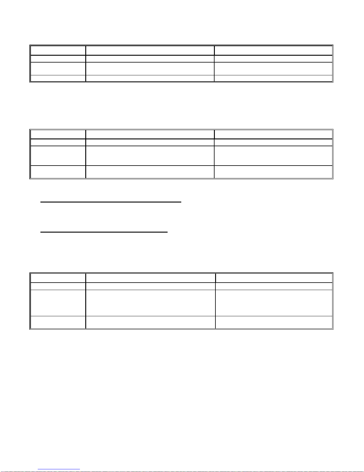
LED Indicators
LED Status Description
LED GREEN blinking every 1.5 seconds.
LED GREEN on/off moderately
LED GREEN blinking every 0.6 seconds.
LED GREEN on/off fast
LED GREEN on
LED RED on
LED RED on/off fast.
LED RED blinking every 0.4 seconds.
-
-
-
-
-
-
-
-
Power on, in User Mode, normal condition.
System waits for PIN or Function Code inputs completed.
The system is in arming situation.
System is in Edit Mode.
Valid card present or all the successful operations.
Invalid card present or all the fail operations.
The system is busy.
Alarm signal is activated.
Audible Beep
1 short beep
2 short beep
4 short beeps
5 short beeps
-
-
-
-
Key pressed;
Valid card present;
In User Mode, the PINor Function Code input sequences completed;
In Edit Mode, successful operation.
Invalid card present;
Operation failed.
In User Mode, wait for PIN Code input.
In Registration processing, card has already been registered;
System is disarmed;
Violate anti-passback.

2
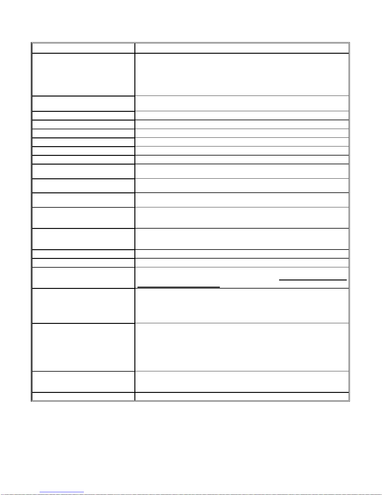
Functions Description
Function Description
Door Unlock Time Setting Assign Door Unlock Time (or Door Relay Activated Time). The Door Unlock
Time is keypad programmable and can be programmed as-
Toggle Mode: Latched-on/Latched-off or
Momentary Mode: 1 ~ 600 seconds or 0.1 ~ 39.9 seconds.
Default setting: 2 seconds.
Alarm Time Setting Assign Alarm Time (or Alarm Relay Activated Time). The Alarm Time is
keypad programmable and can be programmed as-
Latched-on Mode or
Momentary Mode: 1 ~ 600 seconds
Default setting: 2 seconds.
Arming Delay Time Setting Once the arming function is set, after a certain period of Arming Delay Time,
the system will enter Arming Mode and 1) the system engages the Timing 2
Sequencesif door is close or 2) wait until door is closed to engage the Timing 2
Sequences if door is open. By setting Arming Delay Time, user can have
enough time to go out without activating the alarm system. The Arming Delay
Time is keypad programmable and can be programmed from 1 ~ 600 seconds.
Default setting: 1 second.
Alarm Delay Time Setting When the door is close and the system is in Arming Mode, open the door will
activate the alarm relay after a certain period of delay time (Door Unlock Time
+ Arming Idle Time + Alarm Delay Time). To avoid the alarm generated, user
can close the door within "Door Unlock Time + Arming Idle Time" delay period
and system is still in Arming Mode, or just enter disarm process within "Door
Unlock Time + Arming Idle Time + Alarm Delay Time" period and system is in
Disarming Mode.The Alarm Delay Time is keypad programmable and can be
programmed from 1 ~ 600 seconds.
Default setting: 3 seconds.
If door is opened and in Latched-off mode, the delay time is infinite and there
will be no alarm activated.
Arming Idle Time Setting This idle time can provide user an enough time to close the door without
entering Alarm Delay Time period. Once system enters Alarm Delay Time
period, the user has to disarm the system to avoid the alarm generated. The
Arming Idle Time is keypad programmable and can be programmed from 1 -
600 seconds.
Default setting: 15 seconds.
Power on Arming After power on, the arming is set automatically and system enters Time 1
Sequence. This feature is keypad programmable. Please refer to Command 20.
Default setting: Disable power on Arming.
Door Monitored & Re-lock To prevent "tailgating", door is monitored and automatically locked when entry is
completed and door is closed for at least 2 seconds.
This feature is keypad programmable and isn't effective if the Door Unlock
Time setting is in Latched-on mode. Please refer to Command 20.
Default setting: Disable Auto Re-lock function.
Door Exit Release A door exit push-button or infrared detector to unlock the door from inside.
This feature is keypad programmable. Please refer to Command 20.
(Note: Push-button switch or infrared detector is not included).
Default setting: Enable Door Exit Release function.
Audible output Audible beep sound to indicate the status of key pressed or successful operation
or operation failed.
Edit Mode Timeout If no entry is made within 30 seconds, the system will exit the Edit Mode and
return to its normal operation, i.e. User Mode.
Keypad Automatic Blocking Keypad will be locked for 30 seconds if wrong key-entries are made 3 times in
User Mode. A valid or invalid card can release the keypad from blocking during
these 30 seconds.
For all the valid inputs, either by cards or by keys, the error counter will reset to
0.
For the invalid card input, the error counter will reset to 1.

3
Forced Open Alarm If door is forced open, Alarm Relay will be activated. Refer to Command 28.
PIN Code Changeable Cards with "Card and PIN Code", or "Card or PIN Code" access mode can
change the PIN Code in User Mode by just press new PIN Code twice followed
with # sign in 3 seconds after access is successful.
Tamper Protection A built-in tamper switch (C, NC, NO) to prevent the reader from removing.
Arming/Disarming The designated door can be armed or disarmed.
Arming can be reset by either entering the Edit Mode or the disarm process.
Anti-passback 721H5 reader can be connected to 721K or 721U read head to per
form
Anti-passback feature. Individual card can access the reader in an anti-passback
manner only when it is selected to have an anti-passback function by
Command
26 and also the reader is defined to have anti-passback feature by
Command
20.
Default setting: Disable Anti-passback function.
Non-volatile EEPROM Will save all of the codes and system parameters when power is off.
Alarm LED and Alarm Reset Alarm LED and Alarm, if it is still activated, can be reset by entering the Edit
Mode, or by entering the disarming process.
System Programming Guide
Commands Description
*
PPPPPP# or follow step 1 & 2
1. Present card with address
#00000 to the reader, and input PIN
Code and # sign if the card is in
"Card and PIN Code" access
mode. 2. Press # key in 3 seconds.
PPPPPP= 6-digit Password.
Either way can enter Edit Mode.
Default setting: PPPPPP= 123456.
*
# or
**
#Either way can exit Edit Mode and then in User Mode, however
**
#will also
set the arming.
00
*
NNN# Assign a Reader Number 001 ~ 254 to itself.
If NNN=000 or NNN> 254, system will assign a default setting.
Default setting: NNN= 001.
02
*
TTT# Door Unlock Time Setting. Forever or 1 ~ 600 seconds or 0.1 ~39.9 seconds.
Toggle Mode: TTT= 000 for forever.
Momentary Mode: TTT= 001 ~ 600 for 1 ~ 600 seconds.
TTT= 601 ~ 999 for 0.1 ~ 39.9 seconds. (TTT –600) x 0.1
Default setting: TTT= 002
03
*
TTT# Alarm Time Setting. Forever or 1 ~ 600 seconds.
Latched-on Mode: TTT= 000 for forever.
Momentary Mode: TTT= 001 ~ 600.
If TTT>600, system will assign a default setting.
Default setting: TTT= 002
05
*
TTT# Arming Delay Time Setting. 1 ~ 600 seconds.
TTT= 001 ~ 600.
If TTT>600, system will assign a default setting.
Default setting: TTT= 001
06
*
TTT# Alarm Delay Time Setting. 1 ~ 600 seconds.
TTT= 001 <-> 600.
If TTT>600, system will assign a default setting.
Default setting: TTT= 003
09
*
NNNNNNnnnnnn# Change Edit Password. User has to enter new password twice.
NNNNNN: new password, 000000 ~ 999999.
nnnnnn: new password, 000000 ~ 999999.
10
*
SSSSS
*
EEEEE# Disable the proximity cards with addresses starting from SSSSS to EEEEE.
After disabled, the cardholder(s) can't access the system.

4
SSSSS: 00000 ~ 00999
EEEEE: 00000 ~ 00999
If SSSSS>EEEEE or SSSSS>00999 or EEEEE>00999, error message.
10
*
SSSSS9EEEEE# Delete the proximity cards with addresses starting from SSSSS to EEEEE
from
system.
SSSSS: 00000 ~ 00999
EEEEE: 00000 ~ 00999
If SSSSS>EEEEE or SSSSS>00999 or EEEEE>00999, error message.
11
*
SSSSS
*
EEEEE# Enable the proximity cards with addresses starting from SSSSS to EEEEE. After
enabled, the cardholder(s) can access the system by using "Card Only" mode.
SSSSS: 00000 ~ 00999
EEEEE: 00000 ~ 00999
If SSSSS>EEEEE or SSSSS>00999 or EEEEE>00999, error message.
12
*
SSSSS
*
PPPP# Enable a proximity card with addresses SSSSS and assign a PIN Code PPPP
to it. After assigned, the cardholder can access the system by using "
Card or
PIN Code" mode. For example:
After entering 12
*
00005
*
7766#, user can access the door by just either
‘presenting the card with address #00005 to the reader’ or “entering the address
no. 00005 and then 7766#.
SSSSS: 00000 ~ 00999
PPPP: 0001 ~ 9999
If SSSSS>00999, error message.
13
*
SSSSS
*
PPPP# Enable a proximity card with addresses SSSSS and assign a PIN Code PPPP
to it. After assigned, the cardholder can access the system by using " Card and
PIN Code" mode. For example:
After entering 13
*
00005
*
7766#, user can access the door by just presenting
the card with address #00005 to the reader and then entering 7766#.
SSSSS: 00000 ~ 00999
PPPP: 0001 ~ 9999
If SSSSS>00999, error message.
17
*
FFFF# Assign 4-digit Function Code FFFF.
Function Code followed with <#> to Arm or Disarm the system.
Function Code followed with <DEV> to activate the Alarm Relay.
FFFF: 0001 ~ 9999
Default setting: FFFF= 1234
18
*
TTT# Arming Idle Time Setting. 1 ~ 600 seconds.
TTT= 001 ~ 600.
If TTT>600, system will assign a default setting.
Default setting: TTT= 015
19
*
SSSSS
*
NNNNN# Register a number of card(s) to the system. After registered, the cardholder can
access the system by using "Card Only" mode. Note: Cards can not be
registered through 721K or 721U.
SSSSS: 00000 ~ 00999. Register Card(s) with addresses starting from SSSSS.
NNNNN: Indicate a number of card(s) to be registered.
If NNNNN= 00001 Single card registration.
Card Codes can be either in sequential or in random, after #sign, user can
register the proximity cards to the system by present the cards to the reader
panel one by one continuously. For each valid card registration, the system will
automatically assign a group number to each card and increment the address by
one. Before each registration, system will also perform the following checking: A
card registered can not be registered again, five beep tones are generated
to indicate this error.
If NNNNN= 00002 –00999 Block registration.
If Card Codesare in sequential with same Site Code, after #sign, user can
register the proximity cards to the system by just present the card with the
lowest Card Code to the reader panel. The system will automatically assign a
group number and the addresses starting from SSSSS to the proximity cards.
System will refuse the block registration if card(s) is (are) registered
before, five beep tones are generated to indicate this error. Cards have
already been registered in these block addresses will be overwritten.
Cards with same Site Code are automatically assigned to same group number

5
even it is not registered at the same time.
If NNNNN=00000, error message.
If NNNNN>available addresses, system will assign all the available addresses
and then quit.
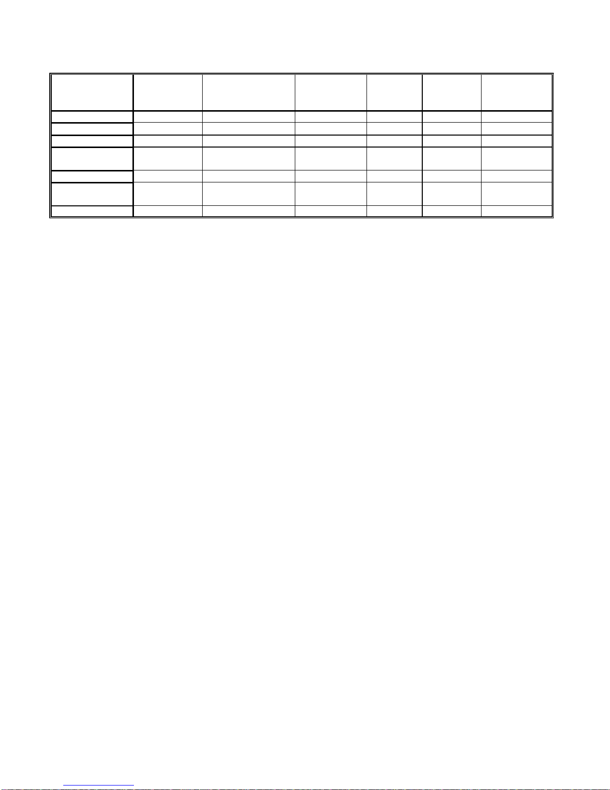
20
*
NNN# System parameters setting.
Auto Re-lock: disable value 000; enable value 002
Power on Arming: disable value 008; enable value 000
Door Exit Release: disable value 000; enable value 016
Anti-passback: disable value 000; enable value 128
NNN: 000 ~ 255
For example:
Auto Power on Door Exit Anti-
NNN Re-lock Arming Release Passback
000 disable enable disable disable
002 enable enable disable disable
008 disable disable disable disable
010 enable disable disable disable
016 disable enable enable disable
018 enable enable enable disable
024 disable disable enable disable
026 enable disable enable disable
128 disable enable disable enable
130 enable enable disable enable
136 disable disable disable enable
138 enable disable disable enable
144 disable enable enable enable
146 enable enable enable enable
152 disable disable enable enable
154 enable disable enable enable
If NNN>255, system will assign a default setting.
Default setting: NNN= 024
26
*
SSSSS
*
EEEEE
*
X# Define the proximity cards with addresses starting from SSSSS to EEEEE.to
have or not to have an anti-passback feature. For example:
If enter 26
*
00005
*
00008
*
1#, cards with addresses from 5 ~ 8 do not have
anti-passback feature.
If enter 26
*
00005
*
00008
*
0# & 26
*
00005
*
00008
*
2#, cards with addresses
from 5 ~ 8 have anti-passback feature. The first entry can be made through
either 721H5 or 721K/721U.
SSSSS: 00000 ~ 00999
EEEEE: 00000 ~ 00999
X: 1-disable anti-passback; 0-enable anti-passback;
2-enable first entry can be made through either 721H5 or 721K/721U.
If SSSSS>EEEEE or SSSSS>00999 or EEEEE>00999, error message.
28
*
NNN#Disarming Forced Open parameter setting.
NNN: 000 –Without Forced Open feature in Disarming mode.
NNN: 128 –With Forced Open feature in Disarming mode.
Default setting: NNN= 000
29
*
29
*
#Delete all the proximity cards and all the Group Numbers.

6
Default Settings
Door Unlock Time Setting 2 seconds
Alarm Time Setting 2 seconds
Arming Delay Time Setting 1 second
Alarm Delay Time Setting 3 seconds
Arming Idle Time Setting 15 seconds.
Edit Mode Timeout 30 seconds
Keypad Blocking Time 30 seconds
Function Code 1234
Auto Re-Lock Disable
Power on Arming Disable
Door Exit Release Enable
Anti-passback Disable
Hardware Specifications
Power Input 10 ~ 12 VDC
Power Consumption 200mA
Door Relay Output COM, NC and NO, 2A/30VAC; 2A/24VDC
Alarm Signal Output Transistor output, active low, 12VDC/100mA Max.
Tamper Switch Output 1 SPDT, 1A/24VAC; 1A/24VDC
Door Monitor Input C and NC contacted when door closed
Door Exit Release Input NO, active low
Operation Temperature 0oC ~ 50oC
7
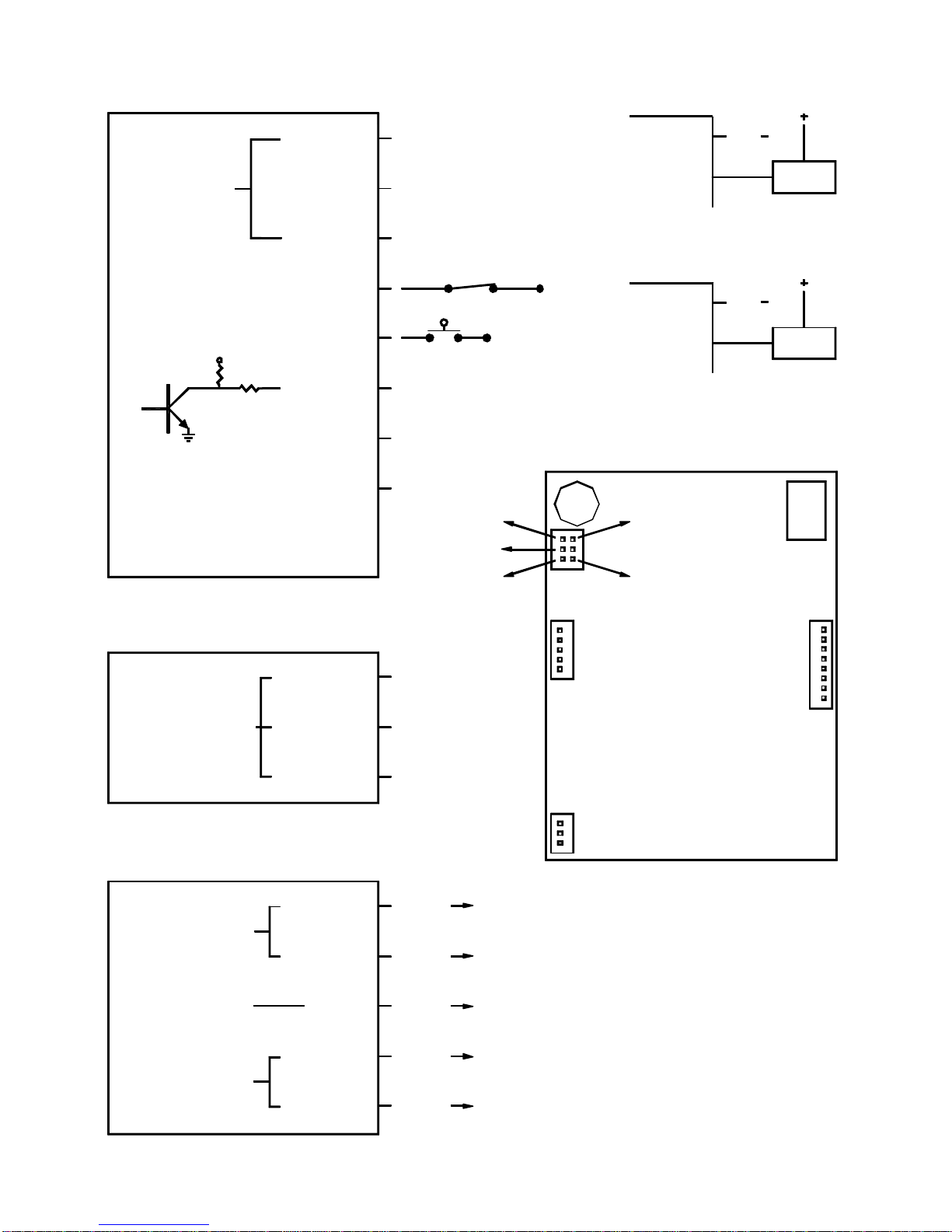
CN3
LOCK
BLUE/W
PURPLE/W
WHITE
ORANGE
RED
BLACK
ALARM SIGNAL
OUTPUT
NO
Reed Switch
DOORRELAY
2A/30VAC
2A/24VDC
Transistor Output, Active Low
NC
COM
Contacted When Door Closed
PURPLE
GREEN
PINK
BROWN
YELLOW
WIEGAND INPUT
Push Button
GND
GND
LED OUTPUT
10 - 12 VDC
GND
NPN
5V
10K 27 100 mA/12VDC Max.
YELLOW
ORANGE
RED
CN3
CN2
CN1
TAMPER SWITCH
1A/24VAC
1A/24VDC
NC
C
NO
WHITE
PURPLE/W NC
CGND
Power To Lock POSITIVE
( )
( )
( )
BLUE/W
WHITE
NO
CGND
LOCK
( )
POSITIVE
Power To Open
GRAY
BLUE DAT(1) 721K CN2 BLUE
DAT(0) 721K CN2 GREEN
LED G. 721K CN2 BROWN
LED R. 721K CN2 YELLOW
721K CN2 PINKBUZZ.
BUZZEROUTPUT
CN2
CN1
721H5 PCB
or 721U BLUE
or 721U GREEN
or 721U PURPLE
or 721U BROWN
or 721U YELLOW
CN4
721L BROWN
721L WHITE
721L PURPLE 721L YELLOW
721L BLACK
721H5 READER WIRING:

8
GREEN
ORANGE
N.A.
WIEGANDOUTPUT
CN2
CN1
721K READ HEAD WIRING:
BLUE DAT(1)
DAT(0)
N.A.
N.A.
CN2
CN1
721K PCB
BLACK
RED 9 - 12 VDC
GND
LED INPUT
LED R.
LED G.
BROWN
YELLOW
BUZZER INPUT PINK BUZZ.
WIEGAND WIRING
LED INPUT
BUZZER INPUT
ABAII OUTPUT
CN2
LED G.
LED R.
BROWN
YELLOW
CLOCK
DATA
BUZZ.
CARD PRESENT
ORANGE
PINK
N.A. N.A.
BLUE
GREEN
ABA II WIRING
1A/24VDC
1A/24VAC
TAMPERSWITCH
CN3
ORANGE
YELLOW NO
C
RED NC
CN3
WG/ABA
BITS
WG/ABA
BITS
WG/ABA
BITS
ABA II: WG/ABA
BITS
Wiegand 26 Bits:
Wiegand 34 Bits:

9
GREEN
PURPLE
WHITE
WIEGAND OUTPUT
721U READ HEAD WIRING:
BLUE DAT(1)
DAT(0)
N.A.
BLACK
RED 9 - 12 VDC
GND
LED INPUT
BUZZER OUTPUT GRAY BUZZ. OUT
WIEGAND WIRING
PURPLE
WHITE
BROWN
BROWN LED G.
YELLOW LED R.
BUZZER INPUT BUZZ. IN
721L ON LINE MODULE WIRING:
TO 721H5 CN4
LED R.
YELLOW
BUZZER OUTPUT
ABA II OUTPUT
BUZZER INPUT
LED INPUT
CARD PRESENT
BUZZ. OUT
WHITE
GRAY
CLOCK
DATA
LED G.
BUZZ. IN
BLUE
GREEN
PURPLE
BROWN
ABA II WIRING
9 - 12 VDC
GND
BLACK
RED
721U PCB
34/26
ABA
Wiegand 34 BITS:
ABA
34/26
ABA
Wiegand 26 BITS:
34/26
ABA
34/26
ABA II:
GREENGREEN RS485 B-
+12VDC
RED
RS485 TO 701E/704E/716E
RS485 A+
BLUE
YELLOW
BLACK
CONTROLLER
RS-232:
34/26
ABA
BUZZ. IN
TTL INVERTED SERIAL OUTPUT
BUZZ. OUT
CARD PRESENT
BUZZER OUTPUT
BUZZER INPUT
GRAY
PURPLE
GREEN
WHITE
9 - 12 VDC
LED G.
TTL SERIAL OUTPUT
LED R.
LED INPUT
RS-232OUTPUT
YELLOW
BROWN
BLUE
RED
BLACK GND
RS-232 WIRING
(Connect to PC COM port through RS232 invert driver)
(Can connect to PC COM port)

10
Arming Delay Timing
Timing 1 Sequence-
After arming is set, the system enters T
Ti
im
mi
in
ng
g
1
1
S
Se
eq
qu
ue
en
nc
ce
e. Right on C
Ch
he
ec
ck
k
P
Po
oi
in
nt
t
A
A, the system is in arming situation
and enters Arming Mode, if door is close, the system engages the Timing 2 Sequences, if door is open, it will wait until
the door is closed to engage the Timing 2 Sequences.
Timing 2 Sequences-
Door opened by not using “Forced Open”:
In arming situation, the system enters T
Ti
im
mi
in
ng
g
2
2
S
Se
eq
qu
ue
en
nc
ce
es
sonce the door is opened by not using “Forced Open”. During
T
Ti
im
me
e
P
Pe
er
ri
io
od
d
B
B, the system is back to arming situation if door closed, if door is still open right on C
Ch
he
ec
ck
k
P
Po
oi
in
nt
t
C
C, alarm is
activated after T
Ti
im
me
e
P
Pe
er
ri
io
od
d
D
D. User can disarm the system in T
Ti
im
me
e
P
Pe
er
ri
io
od
d
D
Dto avoid the alarm generated, or disarm the
system in T
Ti
im
me
e
P
Pe
er
ri
io
od
d
E
Eto turn off the alarm which is activating.
Door opened by using “Forced Open” and if “Forced Open” feature, Command 28, is disabled:
In arming situation, the system enters A
Al
la
ar
rm
m
D
De
el
la
ay
y
T
Ti
im
me
eright away once the door is opened by using “Forced Open” and
if “Forced Open” feature is disabled. The alarm is activated after T
Ti
im
me
e
P
Pe
er
ri
io
od
d
D
D. User can disarm the system in T
Ti
im
me
e
P
Pe
er
ri
io
od
d
D
Dto avoid the alarm generated, or disarm the system in T
Ti
im
me
e
P
Pe
er
ri
io
od
d
E
Eto turn off the alarm which is activating.
Door opened by using “Forced Open” and if “Forced Open” feature, Command 28, is enabled:
In arming situation, the alarm is generated and system enters A
Al
la
ar
rm
m
T
Ti
im
me
eright away once the door is opened by using
“Forced Open” and if “Forced Open” feature is enabled. User can disarm the system in T
Ti
im
me
e
P
Pe
er
ri
io
od
d
E
Eto turn off the
alarm which is activating.
Timing 2
Sequences Alarm TimeAlarm Delay Time
Check Point C
Arming Idle TimeDoor Unlock Time
Door is opened
Time Period B Time Period D Time Period E
Arming Delay Time
Timing 1
Sequence
Check Point A
Arming is set

11
Examples:
* Cards as below:
Card A: 58112:55894 "Card Only"; Card B: 58112:15442 "Card or PIN Code";
Card C: 00053:29278 "Card and PIN Code"; Card D: 58112:11220 "Card Only";
Card E: 00053:30809 "Card Only"; Card F: 01204:19246 "Card Only";
Card G: 01204:19247 "Card and PIN Code"; Card H: 01204:19248 "Card or PIN Code";
Card I: 01204:19262 "Card Only"; Card J: 01204:19263 "Card and PIN Code";
Card K: 20238:03476 "Card Only"; Card L: 20238:03477 "Card Only";
Card M: 20238:03478 "Card Only"; Card N: 20238:03479 "Card Only";
* Change edit password from 123456 to 654321.
* Door Unlock Time: 5 seconds.
* Function Code: 5555.
Examples in Edit Mode:
Command Description
*
123456# Enter Edit Mode.
29
*
29
*
#Delete all the proximity cards.
19
*
00000
*
00001# Register Command. Individual registration.
Present Card A Card A is registered, system assigns group #00 and address #00000 to it.
The system is in 19
*
00001
*
00001# command.
Present Card B Card B is registered, system assigns group #00 and address #00001 to it.
The system is in 19
*
00002
*
00001# command.
Present Card C Card C is registered, system assigns group #01 and address #00002 to it.
The system is in 19
*
00003
*
00001# command.
Present Card D Card D is registered, system assigns group #00 and address #00003 to it.
The system is in 19
*
00004
*
00001# command.
Present Card B Card B was registered before, five beep tones are generated to indicate this error.
The system is still in 19
*
00004
*
00001# command.
Present Card E Card E is registered, system assigns group #01 and address #00004 to it.
The system is still in 19
*
00005
*
00001# command.
12
*
00001
*
1234# Assign PIN Code 1234 to Card with address #00001. I.E. Card B.
19
*
00005
*
00001# Register Command. Individual registration.
Present Card C Card C was registered before, five beep tones are generated to indicate this error.
The system is still in 19
*
00005
*
00001# command.
19
*
00005
*
00003# Register Command. Register 3 cards at a time. Starting address #00005.
Present Card F
Cards F, G and H are registered, system assigns group #02 and address #00005, #00006 and
#00007 to card E, F and G individually.
The system exits the 19
*
00005
*
00003# command.
13
*
00002
*
2222# Assign PIN Code 2222 to Card with address #00002. I.E. Card C.
19
*
00008
*
00002# Register Command. Register 2 cards at a time. Starting address #00008.
Present Card C Card C was registered before, five beep tones are generated to indicate this error.
The system is still in 19
*
00008
*
00002# command.
Present Card I Cards I and J are registered, system assigns group #02 and address #00008 and #00009 to
card E, F and G individually.
The system exits the 19
*
00008
*
00002# command.
13
*
00006
*
3456# Assign PIN Code 3456 to Card with address #00006. I.E. Card G.
12
*
00007
*
1072# Assign PIN Code 1072 to Card with address #00007. I.E. Card H.
13
*
00009
*
9999# Assign PIN Code 9999 to Card with address #00009. I.E. Card J.
09
*
654321654321# Change programming password to 654321 by entering it twice.
02
*
005# Set Door Unlock Time to 5 seconds.
17
*
5555# Set Function Code 5555.
10
*
00003900004# Delete #00003, Card D and #00004, Card E.
16
*
02
*
0000800000# Delete #00008, Card I.

12
19
*
00003
*
00004# Register Command. Register 4 cards at a time. Starting address #00003.
Present Card K
Cards K, L, M and H are registered, system assigns group #03 and address #00003, #00004,
#00005 and #00006 to card K, L, M and N individually. Card F and Card G are overwritten.
The system exits the 19
*
00003
*
00004# command.
*
#Exit Edit mode.
Examples in User Mode:
Action Description
Present Card A Door unlocked for 5 seconds.
Present Card B Door unlocked for 5 seconds.
00001
1234# 00001, Card B, was assigned "Card or PIN Code" access mode.
Door unlocked for 5 seconds.
PIN Code has to be entered in 3 seconds after present card.
Present Card C
2222# 00002, Card C, was assigned "Card and PIN Code" access mode.
Door unlocked for 5 seconds.
PIN Code has to be entered in 3 seconds after present card.
*
123456# PASSWORD ERROR! New password is 654321. Error count is 1.
*
123456# PASSWORD ERROR! New password is 654321. Error count is 2.
Invalid Card Present Invalid card present, error count reset to 1.
Present Card A Valid card present, error count reset to 0.
*
123456# PASSWORD ERROR! New password is 654321. Error count is 1.
*
123456# Wrong password. Error count is 2.
*
123456# Wrong password. Error count is 3. Keypad blocked 30 seconds.
Present Card A Valid card present, error count reset to 0. Keypad unblocked.
Present Card N Door unlocked for 5 seconds.
Present Card A Door unlocked for 5 seconds.
00001
1234#
5555#
00001, Card B, was assigned "Card or PIN Code" access mode.
Door unlocked for 5 seconds.
The arming is set, and system enters Timing 1 Sequences.
Present Card B
5555# Door unlocked for 5 seconds.
Disarm the system.
Note:
PIN Code and Function Code can be the same code.
13
Access Command Formats:
Door Access Command Formats-
Access Mode
Command Format Example
Card Only <present valid card> :<present Card A>
Card or PIN Code <present valid card>
<valid address>-<PIN Code #>:<present Card B>
:<00001>-<1234#>
Card and PIN Code <present valid card>-<PIN Code #>:<present Card C>-<2222#>
There are 5 seconds timeout limitation between <valid address> and <PIN Code #>; between <present valid card> and
<PIN Code #>; and between each key pressed.
Functions Command Formats-
Access Mode
Command Format Example
Card Only <present valid card>-<Function Code>-#:<present Card A>-<5555>-#
Card or PIN Code <present valid card>-<Function Code>-#
<valid address>-<PIN Code #>-
<Function Code>-#
:<present Card B>-<5555>-#
:<00001>-<1234#>-<5555>-#
Card and PIN Code <present valid card>-<PIN Code #>-
<Function Code>-#:<present Card J>-<9999#>-5555>-#
There are 3 seconds timeout between <present valid card> and <Function Code>;
between <PIN Code #> and <Function Code>;
i.e. User has 3 seconds to start inputting the Function Code.
There are 5 seconds timeout between <valid address> and <PIN Code #>;
between <present valid card> and < PIN Code #>;
between each key pressed;
i.e. User has 5 seconds to start inputting the PIN Code.
If last # pressed, either command above can toggle to arm or disarm the system.
PIN Code Change Command Formats-
Access Mode
Command Format Example
Card Only NA -NA
Card or PIN Code <present valid card>-<new PIN Code>-
<new PIN Code>-<#>
<valid address>-<PIN Code #>-<new PIN
Code>-<new PIN Code>-<#>
:<present Card B>-<7799>-<7799>-<#>
:<00001>-<1234#>-<7799>-<7799>-<#>
Card and PIN Code <present valid card>-<PIN Code #>-
<new PIN Code>-<new PIN Code>-<#>:<present Card G>-<3456#>-<7799>-
<7799>-<#>
There are 3 seconds timeout limitation between <present valid card> and <new PIN Code>;
between <PIN Code #> and <new PIN Code>;
14
System Programming Guide –Quick Reference
Commands Description
*
PPPPPP# or follow step 1 & 2
1. Present card with address
#00000 to the reader, and input PIN
Code and # sign if the card is in
"Card and PIN Code" access
mode. 2. Press # key in 3 seconds.
PPPPPP= 6-digit Password.
Either way can enter Edit Mode.
Default setting: PPPPPP= 123456.
*
# or
**
#Either way can exit Edit Mode and then in User Mode, however
**
#will also
set the arming.
00
*
NNN# Assign a Reader Number 001 ~ 254 to itself.
02
*
TTT# Door Unlock Time Setting. Forever or 1 ~ 600 seconds or 0.1 ~39.9 seconds.
03
*
TTT# Alarm Time Setting. Forever or 1 ~ 600 seconds.
05
*
TTT# Arming Delay Time Setting. 1 ~ 600 seconds.
06
*
TTT# Alarm Delay Time Setting. 1 ~ 600 seconds.
09
*
NNNNNNnnnnnn# Change Edit Password. User has to enter new password twice.
10
*
SSSSS
*
EEEEE# Disable the proximity cards with addresses starting from SSSSS to EEEEE.
After disabled, the cardholder(s) can't access the system.
10
*
SSSSS9EEEEE# Delete the proximity cards with addresses starting from SSSSS to EEEEE
from
system.
11
*
SSSSS
*
EEEEE# Enable the proximity cards with addresses starting from SSSSS to EEEEE. After
enabled, the cardholder(s) can access the system by using "Card Only" mode.
12
*
SSSSS
*
PPPP# Assign a PIN Code PPPP to an individual card with address SSSSS. After
assigned, the cardholder can access the system by using " Card or PIN Code"
mode.
13
*
SSSSS
*
PPPP# Assign a PIN Code PPPP to an individual card with address SSSSS. After
assigned, the cardholder can access the system by using " Card and PIN Code"
mode.
17
*
FFFF# Assign 4-digit Function Code FFFF.
18
*
TTT# Arming Idle Time Setting. 1 ~ 600 seconds.
19
*
SSSSS
*
NNNNN# Register a number of card(s) to the system. After registered, the cardholder can
access the system by using "Card Only" mode. Note: Cards can not be
registered through 721K or 721U.
20
*
NNN# System parameters setting.
Auto Re-lock: disable value 000; enable value 002
Power on Arming: disable value 008; enable value 000
Door Exit Release: disable value 000; enable value 016
Anti-passback: disable value 000; enable value 128
26
*
SSSSS
*
EEEEE
*
X# Define the proximity cards with addresses starting from SSSSS to EEEEE.to
have or not to have an anti-passback feature.
SSSSS: 00000 ~ 00999
EEEEE: 00000 ~ 00999
X: 1-disable Anti-passback; 0-enable Anti-passback;
2-enable first entry can be made through either 721H5 or 721K/721U.
If SSSSS>EEEEE or SSSSS>00999 or EEEEE>00999, error message.
28
*
NNN# Disarming Forced Open parameter setting.
NNN: 000 –Without Forced Open feature in Disarming mode.
NNN: 128 –With Forced Open feature in Disarming mode.
29
*
29
*
#Delete all the proximity cards and all the Group Numbers.
15
Various Types of Models
Model Max.
Card Holder Sequential or
Random ID Code
Max.
Card Block
or Group No. Access
Mode Type Keypad or
PC Edit
721H5 1000 Don't care 48 TYPE 1 Standalone Keypad or PC
721H6 65000 Sequential 1TYPE 3 Standalone Keypad
721H7 1000 Don't care 48 TYPE 1 Standalone Keypad or PC
721H7+721L+
721R32 1000 (door)
630 (elevator) Don't care 48 TYPE 1 Standalone
Elevator Keypad or PC
721H7+721L 5000 Don't care 48 TYPE 1 Network PC
721L+721H7+
721L+721R32 5000 (door)
630 (elevator) Don't care 48 TYPE 1 Network
Elevator PC
Keypad
721H5+721L 5000 Don't care 48 TYPE 1 Network PC
TYPE 1: "Card and PIN Code", or "Card or PIN Code", or "Card Only".
TYPE 3: "Card and Common PIN Code", or "Card Only", or "Common Access Code".
721H6:
The 721H6 is a self-contained and non-tracking standalone single door Proximity Access Control System. It supports
up to 65000 cardholders. Each cardholder can access the door by using one of the three access modes "Card and
Common PIN Code", or "Card Only", or "Common Access Code". 721H6 reader can be also connected with 721K or
721U Wiegand 26/34 Format Output Read Head, ideal for higher security applications.
There is a 10-digit number in each card, 5 digits in the left called Site Code and 5 digits in the right called Card Code.
System can accept only the Card Code in the range from 00001 to 65200, cards with continuous codes is required.
721H7:
The 721H7 is a self-contained and non-tracking standalone Proximity Door Access & Elevator Control Reader. It
supports up to 1000 cardholders for Door Access Control and 630 cardholders for Elevator Control, i.e. only the first
630 (addresses from 000~ 629) cardholders can access the door and also perform the elevator control. Together with one
721L and two 721R32 Elevator Controllers, it can control up to 32 floors elevator. Each 721R32 has 16 relay outputs
and 16 pushbutton inputs. The cardholder can access the elevator by just presenting the card to the reader, and with a
door relay in the reader, it can also perform as Door Access Control Reader. 721H7 reader can be also connected with
721K or 721U Wiegand 26/34 Format Output Read Head, ideal for higher security applications.
There is a 10-digit number in each card, 5 digits in the left called Site Code and 5 digits in the right called Card Code.
Once card is validated, system will automatically assign a group number, from 0 to 47, to it. Cards with same Site Code
are grouped into same group number.
Additional features:
Model 721H7: Connecting with external 721L module, the 701H7 can be performed as On Line Reader.

16
721H7 + 721L: On Line Proximity Reader
The “721H7 + 721L” On Line Proximity Reader is for Networking Proximity Access Control System. Together with
another 721L and two others 721R32 Elevator Controllers, it can control up to 32 floors elevator. Each 721R32 has 16
relay outputs and 16 pushbutton inputs. The networking system, with maximum 5000 cardholders, can connect up to 254
any combination of 701E/704E/716E Controllers. 701E/716E have two channels and each channel can connect up to 8
On Line Readers. 704E has one channel and can connect max. 4 On Line Readers. With the support of software
package 701 Server and 701 Client that run under Windows 95 (with IE 4.0), 98, NT and 2000, system provides with
the abilities of Door Access Control, Time & Attendance, Elevator Control, Card Parking Control, Access Records
Reports, Time & Attendance Daily/Monthly Reports, Projects Management and Operators Authority Level Control.
With a dial-up remote access ability, remote location configuration and data collection can be supported by this feature.
Through the NetBEUI protocol and Local Area Network (For examples: Ethernet), the Server Computer and Client
Computers can be spread throughout many offices and buildings, authorized users can monitor the system by using
either Server Computer or Client Computer in their offices. System also provides with the ability to import bitmap files
for photos. Each cardholder can access the door by using one of the three access modes "Card and PIN Code", or "Card
or PIN Code", or "Card Only".
There is a 10-digit number in each card, 5 digits in the left called Site Code and 5 digits in the right called Card Code.
721H5 + 721L: On Line Proximity Reader
The “721H5 + 721L” On Line Proximity Reader is for Networking Proximity Access Control System. The networking
system, with maximum 5000 cardholders, can connect up to 254 any combination of 701E/704E/716E Controllers.
701E/716E has two channels and each channel can connect up to 8 On Line Readers. 704E has one channel and can
connect max. 4 On Line Readers. With the support of software package 701 Server and 701 Client that run under
Windows 95 (with IE 4.0), 98, NT and 2000, system provides with the abilities of Door Access Control, Time &
Attendance, Elevator Control, Card Parking Control, Access Records Reports, Time & Attendance Daily/Monthly
Reports, Projects Management and Operators Authority Level Control. With a dial-up remote access ability, remote
location configuration and data collection can be supported by this feature. Through the NetBEUI protocol and Local
Area Network (For examples: Ethernet), the Server Computer and Client Computerscan be spread throughout many
offices and buildings, authorized users can monitor the system by using either Server Computer or Client Computer in
their offices. System also provides with the ability to import bitmap files for photos. Each cardholder can access the door
by using one of the three access modes "Card and PIN Code", or "Card or PIN Code", or "Card Only".
There is a 10-digit number in each card, 5 digits in the left called Site Code and 5 digits in the right called Card Code.

17
Standalone/Network System Configuration
721H5 721K
721H5
CASE 1
CASE 2
secured area
unsecured area
unsecured area
install inside install outside
install outside
or
721U
install inside
secured area
CASE 4 721H5
secured area
install outside
CASE 3 721H5 721L to 701E/704E/716E Controller
RS485
to 701E/704E/716E Controller
721L RS485
wire connection
wire connection
wire connection
721K
or
721U
install outside
unsecured area
READER
READER
READER
READER
READ HEAD
READ HEAD
ON LINE MODULE
ON LINE MODULE
18
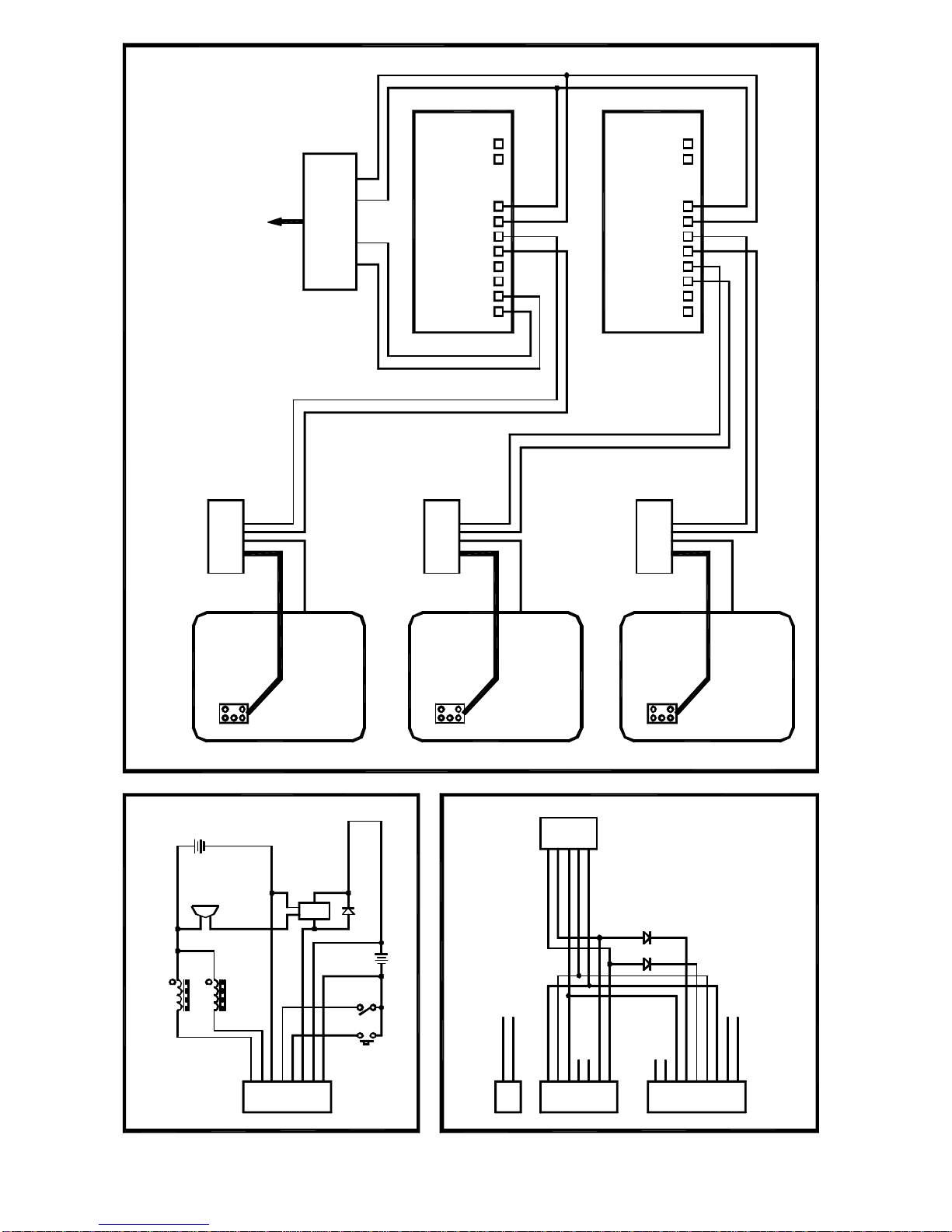
721H Standalone Reader Wiring
721K/721U Read Head Wiring
"721H5 + 721L" On Line Reader Wiring
1
2
3
4
5
6
7
8
CN1
2
1
7
4
3
5
6
CN2 CN2
4
5
2
3
1
9-wire Cable
6
3
2
5
4
8
7
9
CN1
2
1
1
Strike (PTO)
EM Lock (PTL)
+
Alarm
Power for Lock
12/24VDC
721HReader
Pushbutton
Reed switch
purple
orange
white
purple/w
blue/w
red
gray
black
+
NO
NC
COM
relay
Power for Reader, 12VDC
alarm signal output
1N4002
external alarm relay
COMNO
black (GND)
red (+VDC)
yellow (LED R.)
brown (LED G.)
pink (buzz. input)
4
3
green (WD0)
blue (WD1)
gray (buzz. output)
white (card present)
purple (buzz. input)
green (WD0)
blue (WD1)
brown (LED G.)
yellow (LED R.)
black (GND)
red (+VDC)
To 721H Reader Power Input
721K Read Head
721U Read Head
721HReader
pink (buzz. output)
green (WD0)
blue (WD1)
brown (LED G.)
yellow (LED R.)
To 721H Reader Power Input
721U buzzer will be on if gray wire (buzz. output) and purple
wire are connected and card is presented.
721U LED G./LED R. will be on if white wire (card present) and
brown wire/yellow wire is connected and card is presented.
1N4148
Two 1N4148s have to be added to
721U side if there are more than
two read heads are connected to
721H Reader. For example:
NOTE:
If 1x721K & 1x721U are connected,
then 2 1N4148s added to 721U side.
If 2x721Us are connected, then
2 1N4148s added to each 721U side.
If 1x721Us are connected, then no
need to add any 1N4148.
CN4
721H5 Reader
NodeID: 001
721L Module
701E/704E NodeID: 001
V+
GND
LB-
LA+
LB-
LA+
LB-
LA+
9~16 1~8 HOST
Controller Master
701CM Converter
RS232 <-> RS485
TO COMPUTER
NodeID: 002
1~8
LA+
GND
LB-
V+
LB-
701E/704E
Controller
9~16
LA+
LA+
LB-
HOST
Slave
NodeID: 009
721H5 Reader
CN4 721L Module
721H5 Reader
NodeID: 001
CN4 721L Module
cable
+12V (red) LA+(blue)
LB- (green)
+12V (red)
cable LA+(blue)
LB- (green)
cable
+12V (red) LA+(blue)
LB- (green)
LA+(blue)
LB- (green)
LA+(blue)
LB- (green)
black
blue
greenred
Table of contents
Other EMX Industries, Inc. Control System manuals

Popular Control System manuals by other brands


Honeywell
Honeywell Excel 800 LION Installation and commissioning instructions

Compool
Compool Lx220 Installation & operating instructions

Louisiana Grills
Louisiana Grills Country Smokers CS Series quick start guide

Bartec
Bartec ComEx 07-351 Series quick start guide

Record
Record FlipFlow TWIN user manual

SEW-Eurodrive
SEW-Eurodrive IPOS plus manual