EMX IRB-RET User manual
EMX Industries, Inc. Tech support: 216-834-0761 1/8
IRB-RET_Rev2.0_080619 [email protected]
IRB-RET
Universal Retroreflective Photoeye
Instruction Manual
The IRB-RET retroreflective infrared photoeye is an external entrapment protection device type B1,
non-contact sensor for use with automatic gates and doors. Since the reflector directs the beam back to
the photoeye, wiring to the other side of the roadway is not needed. The IRB-RET operates up to 60 feet
over a wide range of voltages (6-40 VDC and 12-24 VAC). A red alignment indicator on the receiver
provides status information at a glance, making set-up and alignment easy. The IRB-RET provides
compatibility with most operators that accommodate monitored external entrapment devices per UL325.
Cautions and Warnings
This product is an accessory or part of a system. Install the IRB-RET according to instructions
from the gate or door operator manufacturer. Comply with all applicable codes and safety
regulations.
Retroreflective photoeyes rely on a reflective surface (a reflector) for proper operation.
In some cases, a vehicle with a reflective surface at a given distance can act as a reflector
and allow the gate to close on a vehicle.
Specifications
Operating Range
5 ft (1.5 m) to 60 ft (18.3 m)
Power
6-40 VDC, 12-24 VAC
ononly)
Current (NC and 10K Monitoring Methods)
60 mA (relay activated)
Current (Pulse Monitoring Methods)
15 mA
Resistive Termination
10K ohm across NO contact (jumper selectable)
Surge Protection
Thermal fuse
Relay Output Operation
Light ON/Dark ON
Relay Output Configuration
Form C contacts (NO, COM, NC)
Transmitter Power Cycle
<300 mS (for use in NC and 10K monitoring)
Methods)
Operating Temperature
-40° to 140°F (-40° to 60°C)
Dimensions (L x W x H)
3.1” (79 mm) x 2.7” (69 mm) x 6.6” (168 mm)
Environmental Rating
NEMA 4X

Ordering Information
•IRB-RET Retroreflective photoeye, includes REFLECTOR-O-EX and mounting bracket
with hardware
•REFLECTOR-O-HD Gray plastic protective hood for reflector
•IRB-RET-HD Black powder-coated steel protective hood for photoeye
•REFLECTOR-O-EX White 3” diameter plastic reflector
Monitoring Methods
UL325 requires continuous monitoring of all safety devices connected to gate and door operators.
Consult the gate or door operator manufacturer’s instruction manual for necessary monitoring
method.
•Normally Closed: Cycles power to the transmitter while monitoring the receiver contacts for proper
operation
•10K Resistive Termination: Provides a measurable 10K ohm resistance across the normally open
(NO) when unobstructed
•Two-wire Pulse (2 Frequency): Provides 300Hz “heartbeat” unobstructed, 0Hz obstructed over
power supply lines
•Two-wire Pulse (3 Frequency): Provides 300Hz “heartbeat” unobstructed, 2Hz obstructed, and
0Hz failure over power supply lines
•Four-wire Pulse (2 Frequency): Provides 300Hz “heartbeat” unobstructed, 0Hz obstructed over
separate connection
•Four-wire Pulse (3 Frequency): Provides 300Hz “heartbeat” unobstructed, 2Hz obstructed, and
0Hz failure over separate connection

Installation
•Determine the mounting location of the IRB-RET photoeye according to UL325 guidelines.
•Deactivate the gate or door during photoeye installation.
•The IRB-RET cannot be used for a detection range of less than 5 feet.
1. Check the instruction manual of the gate
or door operator to determine which
monitoring method is necessary for that
specific operator.
2. Thread all wiring through the mounting
brackets and into IRB-RET as shown.
3. Wire the IRB-RET according to the
configuration table and wiring diagram
that corresponds with the monitoring
method required by the gate or door
operator. MUST USE 6-40 VDC FOR
PULSE MONITORING.
LED Indicators
Green LED & Red LED On
Aligned with reflector, no obstruction
Green LED Flashing & Red LED Off
Beam obstructed or not aligned
Green LED Off
No power
4. Set the sensitivity adjustment to 1/3 of the maximum
by adjusting the potentiometer as shown.
Potentiometer Sensitivity
Adjustment
5. Hold the reflector and stand 4 to 6 feet away from the
IRB-RET. Align the reflector with the photoeye and slowly
back up to the opposite end of the detection zone where
the reflector will be mounted. Move the reflector left,
right, up, and down to find the detection pattern.
(The typical installation will have a 2 foot diameter
pattern.) Mount the reflector as close to the center of the
pattern as possible to assure the strongest signal. If it is
necessary to reposition the photoeye, repeat these steps
to properly position the reflector.
6. If the signal drops out before getting to the desired
distance, increase the sensitivity to 1/2 or 3/4 of the
maximum and repeat step 5.
7. Once the reflector is aligned and mounted, increase the
sensitivity to maximum setting.

8. The IRB-RET is housed in a NEMA 4X enclosure. To ensure the integrity of the enclosure, make sure
the gasket is present, the cover is properly seated, and the cover screws are tight. The wiring to
the enclosure must enter via a UL listed watertight fitting such as a strain relief or watertight
conduit connector.
9. Tighten the mounting screws on the bracket.
10. Verify that the photoeye and reflector are aligned and apply power.
11. Place an obstruction (ex. hand) between the photoeye and reflector. The green LED on the
receiver will flash and the red LED will turn off. Remove the obstruction and the green LED and
red LED will turn on.
12. Check the operator control board and verify that the safety input is recognized by the operator.
Test the beam with an obstruction between transmitter and reflector at multiple distances to
confirm proper operation.
13. Follow the gate or door operator manufacturer’s installation instructions and safety checks to
verify that the photoeye is operating properly.
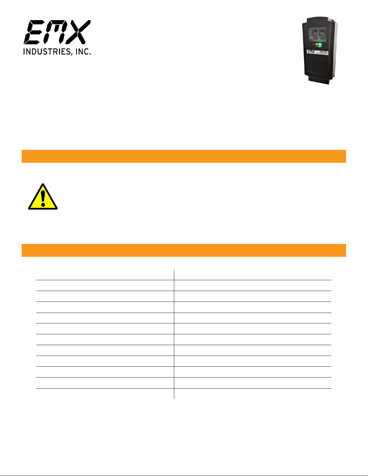
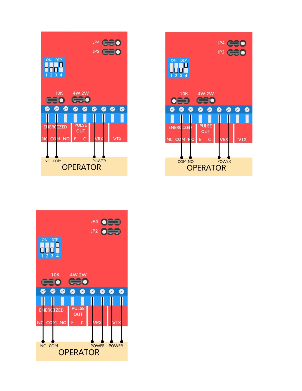
Configuration Settings and Wiring Diagrams
Terminals
Description
VTX
Transmitter power input (non-polarized)
VRX
Receiver power input (non-polarized)
Pulse Out C
Isolated pulse output collector
Pulse Out E
Isolated pulse output emitter
Energized NO
Normally open contact, relay output shown in energized state (power on,
no obstruction) when properly aligned to the reflector
Energized COM
Relay common
Energized NC
Normally closed contact, relay output shown in energized state (power on,
no obstruction) when properly aligned to the reflector.

EMX Industries, Inc. Tech support: 216-834-0761 5/8
IRB-RET_Rev2.0_080619 [email protected]
Configuration Table
•Must use 6-40VDC for pulse monitoring.
•The relay contacts labeled on the terminals and the references to them in these instructions are
shown in the energized state, no obstruction. (Dark ON setting –normally open (NO) contact closes
when the beam is unobstructed.)
•Pulse configurations require current limiting in the operator. The IRB-RET will pulse 300Hz when not
obstructed and 0Hz when obstructed.
•Four-wire output provides an emitter and collector connection to the operator. The emitter is
generally connected to the circuit common (ground) and the collector is typically an open-collector
output using a pull-up resistor to low-voltage DC power.
Monitoring
Method
Wiring
Diagram
DIP Switch Settings
Output
Connections
Power
Connection
Jumpers Installed
SW1
SW2
SW3
SW4
VRX
VTX
JP2
JP4
JP5
JP6
Normally
Closed
A
OFF
OFF
OFF
ON
NC, COM
VRX
Factory
Set
10K
disabled
4W
10K Resistive
Termination
B
OFF
OFF
OFF
ON
NO, COM
VRX
Factory
Set
10K
enabled
4W
Normally
Closed:
Power Cycle
Transmitter
Only
C
OFF
OFF
OFF
ON
NC, COM
VRX
VTX
Separate
Power
RX and
TX
10K
disabled
4W
Two-Wire
Pulse (2
Frequency:
300Hz, 0Hz)
D
ON
OFF
OFF
ON
VRX
DC
Power
only
to
VRX
Factory
Set
10K
disabled
2W
Two-Wire
Pulse (3
Frequency:
300Hz, 2Hz,
0Hz)
D
OFF
ON
OFF
ON
VRX
DC
Power
only
to
VRX
Factory
Set
10K
disabled
2W
Four-Wire
Pulse (2
Frequency:
300Hz, 2Hz,
0Hz)
E
ON
OFF
OFF
ON
E, C
DC
Power
only
to
VRX
Factory
Set
10K
disabled
4W
Four-Wire
Pulse (3
Frequency:
300Hz, 2Hz,
0Hz)
E
OFF
ON
OFF
ON
E, C
DC
Power
only
to
VRX
Factory
Set
10K
disabled
4W
EMX Industries, Inc. Tech support: 216-834-0761 6/8
IRB-RET_Rev2.0_080619 [email protected]
Wiring Diagram A: Normally Closed Wiring Diagram B: 10K Resistive Termination*
*If using the IRB-RET in an application that
does not require UL325 monitoring across the
normally open contact, it is possible to disable
the 10K resistor by moving the 10K jumper to
pins 1 and 2.
Wiring Diagram C: Normally Closed
Power Cycle Transmitter Only

Wiring Diagram D: Two-Wire Pulse
(2 Frequency)
Wiring Diagram D: Two-Wire Pulse
(3 Frequency)
Wiring Diagram E: Four-Wire Pulse
(2 Frequency)
Wiring Diagram E: Four-Wire Pulse
(3 Frequency)

Symptom
Possible Cause
Solution
Does not detect obstruction
Signal is reflecting off another
surface
Check area for highly reflective
surfaces such as a shiny vehicle.
Possible solutions are to move
the photoeye farther away from
the roadway or adjust the
sensitivity counter-clockwise.
Green LED flashes continuously,
indicating an obstruction when
one is not present
Sensitivity is too low
Photoeye is not aligned with
reflector
Adjust sensitivity clockwise
Check alignment, verify
operation with reflector
Photoeye activates but does not
transmit signal to operator
Faulty connection between
photoeye and operator control
input
Verify all wires and terminal
connections to operator
Warranty
EMX Industries, Inc. products have a warranty against defects in materials and workmanship for a period
of two years from date of sale to our customer.
Troubleshooting
Table of contents
Other EMX Protection Device manuals


