Energotest ZL-4A User manual
Solutions contained within this design may be copied and distributed only as a whole.
Copying and/or use part of this design for may take place only upon a written permission issued by
Energotest Ltd
ARC FAULT
PROTECTION
ZŁ-4A
Operating Manual
Gliwice, July 2019

Operating Manual
2
Arc fault protection ZŁ-4A; (07.2019)
Documentation
version
Table of
contents
points
Description
IU_ZŁ-4A ANG
20181127
Original version
IU_ZŁ-4A ANG
20190710
Addition of records about the maximum length of the fiber re-
serve.

Operating Manual
Arc fault protection ZŁ-4A; (07.2019)
3
Energotest reserves the right for making modifications in products for the purpose of im-
provement of the technical quality. These modifications may have not been taken into con-
sideration in this documentation yet.
Brands and names of products mentioned in this instruction are producer’s brand and
should be considered as registered trademarks.
To contact us:
Energotest sp. z o.o.
ul. Chorzowska 44B
44-100 Gliwice
Poland
Phone –Central office: 048-32-270 45 18
Phone –Production Department: 048-32-270 45 18 ext. 40
Phone –Marketing: 048-32-270 45 18 ext. 26
Fax: 048-32-270 45 17
E-mail –Production Department: produkcja@energotest.com.pl
Internet (www): http://www.energotest.com.pl
Copyright © 2016 by Energotest Ltd. All rights reserved.

Operating Manual
4
Arc fault protection ZŁ-4A; (07.2019)
1. MEANING OF OPERATING MANUALS
In case of doubts regarding the appropriate interpretation of the manual's content we
strongly advise you to contact the manufacturer for further explanation.
We will be grateful for any suggestions, opinions and critical remarks and we kindly ask our
customers to deliver them. This may help us to make the manual easier to be used and give
consideration to wishes and requirements of the users.
A device, to which the manual has been prepared, does not cover all potential dangers to
people and material value. That is why every person, working with this device or performing
any activities connected with operating and service of the device, has to be previously
trained and has to know potential hazard. It requires careful reading, understanding and
obeying the operating manual, particularly remarks concerning safety.

Operating Manual
Arc fault protection ZŁ-4A; (07.2019)
5
TABLE OF CONTENTS
1. MEANING OF OPERATING MANUALS................................................................. 4
2. INFORMATION ON COMPLIANCE ....................................................................... 7
3. Application of the unit ............................................................................................. 7
4. Safety rules............................................................................................................. 8
5. ZŁ-4A Technical description................................................................................. 11
5.1. General information....................................................................................... 11
5.2. Functions of particular protection elements................................................... 14
5.2.1. Central unit............................................................................................. 14
5.2.2. Bay unit.................................................................................................. 15
5.2.3. Executive unit......................................................................................... 15
5.2.4. Optical detectors. ................................................................................... 16
5.2.5. Power supply.......................................................................................... 16
5.3. ZŁ-4A front panels......................................................................................... 17
5.3.1. Central unit............................................................................................. 17
5.3.2. Bay unit.................................................................................................. 18
5.3.3. Executive unit......................................................................................... 19
6. Technical data...................................................................................................... 20
7. List of applied standards....................................................................................... 27
8. Information on completeness................................................................................ 28
9. Mounting............................................................................................................... 28
10. Starting up.......................................................................................................... 37
10.1. Registration of bay units.............................................................................. 37
10.2. Optical inputs configuration......................................................................... 38
10.3. Optical inputs checking................................................................................ 38
10.3.1. Check with an external light source...................................................... 38
10.3.2. Check with an embedded test.............................................................. 39
10.4. Voltage measurement input checking.......................................................... 40
11. Using of ZŁ-4A JP control panel......................................................................... 40
11.1. Information on software version .................................................................. 40
11.2. “Ready” status ............................................................................................. 41
11.3. Bay unit configuration.................................................................................. 44
11.4. Error messages........................................................................................... 45

Operating Manual
6
Arc fault protection ZŁ-4A; (07.2019)
11.5. „Tripping” mode ........................................................................................... 46
11.6. Optical detectors test................................................................................... 48
12. Using of ZŁ-4A JW control panel........................................................................ 49
12.1. Information on software version .................................................................. 49
12.2. “Ready” status ............................................................................................. 49
12.3. Executive unit configuration......................................................................... 50
12.4. Error messages........................................................................................... 50
12.5. „Tripping” mode ........................................................................................... 51
13. Using of central unit ZŁ-4A JC control panel ...................................................... 51
13.1. LCD display startup screen ......................................................................... 52
13.2. Control panel menu structure...................................................................... 52
13.3. Menu (pages) review................................................................................... 53
13.3.1. Page 1) JP/JW UNITS.......................................................................... 53
13.3.2. Page 2) STATUS ................................................................................. 59
13.3.3. Page 3) ACTIVATION.......................................................................... 62
13.3.4. Page 4) OCCURRENCES.................................................................... 64
13.3.5. Page 5) TRIPPING............................................................................... 65
13.3.6. Page 6) ALARMS................................................................................. 67
13.3.7. Page 7) CONFIGURATION.................................................................. 69
13.3.8. Page 8) OPTICAL SYSTEM TEST ...................................................... 77
14. Communication ports.......................................................................................... 82
14.1. CAN bus...................................................................................................... 82
14.2. RS485 Interface .......................................................................................... 82
15. Operating............................................................................................................ 95
15.1. Periodic check of the protection operation................................................... 95
15.2. Exchange of optic elements after an arc fault appearance.......................... 95
15.3. Detection and elimination of the damage .................................................... 96
16. Storing................................................................................................................ 96
17. Utilization............................................................................................................ 96
18. Warranty and service.......................................................................................... 97
19. Ordering.............................................................................................................. 97

Operating Manual
Arc fault protection ZŁ-4A; (07.2019)
7
2. INFORMATION ON COMPLIANCE
A device being the subject of this instruction has been constructed and prepared and it is
now manufactured for the purpose of use in industrial environment.
This device is compatible with the following directives:
1. Compatibility System and Market Supervision Act of 13th April 2016 (Dz. U. 2016 pos.
542) as amended.
2. Compatibility System Act of 30th August 2002 (Dz. U. No. 166 pos. 1360) as amended.
3. Decree of Development Minister dated June 2nd 2016 (Dz. U. 2016 pos. 806) imple-
menting the European Parliament Directive Low voltage LVD 2014/35/UE.
4. Polish Act of 13th April 2007 on electromagnetic compatibility (Dz. U. No. 82 pos. 556)
implementing the European Parliament Directive EMC 2014/30/UE.
Compliance with the directives has been confirmed by tests performed in laboratory of Ener-
gotest and also independently of the manufacturer measurement and research laboratories
in accordance with the requirements of the harmonized standards: PN-EN 60255-27:2014-06
(for the LVD directive) and PN-EN 60255-26:2014-01 (for the EMC directive).
3. Application of the unit
The majority of faults in medium or low voltage switchgears are accompanied by an elec-
tric arc, which causes significant damage to equipment and is a great hazard to human life.
Breaking a fault within up to 100 ms enables the avoidance of the most serious damage to
equipment and decreases a hazard to people in the vicinity of the place of fault occurrence.
In case of a long duration of the fault severe injuries, i.e. burns, damage of eyesight etc.,
including loss of life, can occur. Besides, an irreversible and often complete damage to the
switchgear is highly possible.
Because of serious hazard both to people and equipment, according to the regulations of
the European countries, including Poland, it is strongly recommended to undertake effective
preventive measures in medium and low voltage switchgears as well as in transformer
stations to reduce the effects of arc faults.
The fiber optic arc protection type ZŁ-4A localizes arc fault immediately. Considering the
time of operation of the currently used circuit breakers (30-50 ms), the protection system type
ZŁ-4A guarantees that the switchgear or its specific bay will be switched off within
40-60 ms reducing to minimum the effects of arc faults.

Operating Manual
8
Arc fault protection ZŁ-4A; (07.2019)
Additional ZŁ-4A features:
ability to selective switch off the bays where short-circuit appears;
applying the voltage criterion, providing security of the whole switchgear (no unpro-
tected zones) –this criterion is also beneficial in case of parallel running of two
or more incoming feeders on one section of a switchgear;
ability to operate in case of arc fault;
simplicity of solution and housing in already operating and newly built/constructed
switchgears and transformer stations.
ZŁ-4A is dedicated to LV and MV switchgears and transformer stations. Equipping
a switchgear or a transformer station with the arc protection system type ZŁ-4A is the optimal
way to meet the requirements of appropriate standards of protection of the personnel and the
equipment against destructive effects of arc faults.
4. Safety rules
The following chapter presents the information crucial to appropriate installation and op-
eration of the product. It is assumed that the personnel installing and operating this device is
properly qualified and is aware of the potential danger of electrical devices.
The device fulfills all the requirements of obligatory standards and rules regarding safety.
It has been carefully constructed in order to meet the user security demand.
Device Installation
The device should be installed in such a location where proper environmental
conditions specified in technical data are provided Ensure adequate cooling of
the device. Devices should be properly mounted, protected from mechanical
damage and from accidental access of unauthorized persons. Wires cross-sections and
types of connections should be consistent with the guidelines given in this manual. Casings
are made of plastic and do not require grounding.
!

Operating Manual
Arc fault protection ZŁ-4A; (07.2019)
9
Commissioning of device
During a startup of the device its rating plate and the following elements should be care-
fully checked:
continuity of grounding circuits,
fuses,
compliance of values of auxiliary power supply voltage,
compliance of values of measured quantities (voltage),
correctness of applied protections of voltage circuits (nominal values of fuse links
or nominal - currents and characteristics of automatic circuit breakers),
maximum load of relay outputs,
compliance of voltage values of switching outputs,
correctness of mounting all circuits .
Operating of device
The unit should operate in the environment specified in technical data.
Personnel operating the device should be authorized and acquainted with operat-
ing manuals.
Opening the casing
Before starting any activities that require opening the device casing, one should
obligatorily switch off all the measurement and auxiliary voltage supplies and
disconnect all terminals blocks. The dangerous voltage may appear on the de-
vice elements during 1 min after isolating the circuit.
The applied integrated circuits are very sensitive to electrostatic discharges and that is why
opening the unit without special anti-electrostatic equipment may cause its damage.
Service
After installing the device does not require any additional service apart from periodic in-
spection required by applicable regulations. In case of appearance of any defect the user
should ask the producer for help. The producer offers service related to activating, commis-
sioning, guarantee and post guarantee service. Manufacturer’s guarantee terms and condi-
tions are described in the guarantee card.
!
!

Operating Manual
10
Arc fault protection ZŁ-4A; (07.2019)
Modifications and changes
For the sake of security all modifications and changes of the unit functions are forbidden.
Modifications of the device which have not been certified in writing by the manufacturer,
cause loss of any liability claims made against Energotest Ltd.
Exchange of any elements or components the device is composed of, produced
elsewhere, may cause hazard to users and eventually result in incorrect function-
ing.
Energotest does not take any responsibility for damage caused by applying inappropriate
elements or components of the device.
Nominal data, name plates and stickers
It is obligatory to obey instructions located on the device such as descriptions or name
plates and stickers and it is necessary to keep them legible. Plates and stickers, which be-
come damaged or illegible, should be exchanged.
Danger impossible to eliminate
Danger arising from on-load high voltage.
To avoid the electric shock it is suggested not to touch service terminals blocks.
!
!

Operating Manual
Arc fault protection ZŁ-4A; (07.2019)
11
5. ZŁ-4A Technical description
5.1. General information
Fiber optic arc fault protection ZŁ-4A is a device dedicated to diminish all kinds of dam-
age caused by arc faults. It is achieved by fast identification of the fault and breaking all
feeder lines of the fault. The device generates tripping signals to the circuit breakers. There
are two conditions for the fault identification that have to occur at the same time:
voltage drop on protected switchgear busbars,
appearance of arc fault flash.
The device works based on a module structure that includes:
central unit ZŁ-4A JC,
bay units ZŁ-4A JP together with optic detectors:
•point sensor (maximal length 15 m),
•fiber optic loop (maximal length 5 m),
executive units ZŁ-4A JW (additional module - optional).
For the sake of data transfer all the system elements are connected by a CAN bus. The
protection is supplied by 24V DC. This voltage can be obtained from a site guaranteed
24V DC, or from a power supply suggested by the manufacturer supplied from the guaran-
teed 220V DC or 230V AC.
A bay unit should be installed in every bay of the switchgear, i.e., incoming feeder, out-
going, coupling, voltage measurement bays, etc. Each bay unit is equipped with 4 optic de-
tectors, that can be installed differently depending on a particular application (the only re-
quirement is to maintain protection of all bay compartments).
For example:
In an outgoing bay detectors 1 and 2 are typically installed in the busbars and CB compart-
ment, and detectors 3 and 4 in the cable drop compartment (see Fig. 1)
In case of more complicated switchgears with a greater number of compartments addi-
tional bay unit may be required.
Examples of ZŁ-4A installation for one-section, two-section and dual-mode switch-
gears are available at Energotest website.
The best location for the central unit (ZŁ-4A JC) is the voltage measurement bay. Signal
from VT should be plugged in to the central unit. Communication between the various protec-
tion components is via CAN bus. In case of CAN transmission failure between protection
modules, tripping signal is generated based on one condition, namely the light detection.
!

Operating Manual
12
Arc fault protection ZŁ-4A; (07.2019)
Because of the tripping signals distribution three protection zones have been defined.
zone 1 (S1) –includes busbars and CB compartments,
Detection of arc fault by any bay unit (two conditions: activation of optical module and voltage
module) in zone 1 results in activation of tripping signal to open the circuit breaker in the cur-
rent bay and sending information to other bay units in the system. Based on this information
all other bay units generate tripping signal to open the circuit breaker in the bays they pro-
tect. Moreover, the central unit activates proper actuator relays. All the CB in the protected
switchgear are opened.
zone 2 (S2) –includes cable connection compartments of outgoing bays.
Detection of arc fault by any bay unit (two conditions: activation of optical module and voltage
module) in zone 2 results in activation of tripping signal to open the circuit breaker in the cur-
rent bay (selective activation). Other circuit breakers in the protected switchgear remain
closed. Signal indicating a detection of the arc fault in zone 2 is transmitted also to the cen-
tral unit, that activates proper actuator relays.
zone 3 (S3) –includes cable connection and circuit breakers (CB) compartments of
feeder bays (action without voltage condition).
Detection of arc by any bay unit (one conditions: activation of optical module) in zone 3 re-
sults in activation of tripping signal to open the circuit breaker in the protected bay and send-
ing information to central unit. Based on the received information the central unit generates
tripping signal to the circuit breaker in the system that supplies the protected switchgear -
according to the current configuration of executive relays.
You can find the way of installing ZŁ-4A protection modules in an example of the switchgear
in the figure below.

Operating Manual
Arc fault protection ZŁ-4A; (07.2019)
13
Fig. 1 Example of ZŁ-4A installing.
The executive unit is an additional module enabling the generation of trip signals. Each
unit has one executive relay with normally open contact and one signaling relay with
changeover contact. The configuration of the executive relay is identical to that in the central
unit. The maximum trip units in the system are 5.
ZŁ-4A protection can consist of maximal 99 bay units and 5 executive units connected to
one central unit. Total length of CAN bus should be less than 250 meters. There are availa-
ble technical solutions using fiber optic converter which enable the increase of the length of
the CAN bus. Delays of the device tripping associated with these solutions are negligible.
Energotest provides a suitable solution as an option for the entire protection system. The
requirement of increasing the length of the CAN bus should be notified to Energotest during
ordering.

Operating Manual
14
Arc fault protection ZŁ-4A; (07.2019)
5.2. Functions of particular protection elements
5.2.1. Central unit.
The central unit supervises the work of the whole ZŁ-4A protection system. Through the cen-
tral unit the user has access to the information on the current protection states (current set-
tings and signalization of bay and central units) and ability to change the settings ZŁ-4A JC.
The essential functions of the central unit ZŁ-4A JC are the following:
protection configuration regarding communication between system units,
configuration of output relays (associating them to the protection zones),
detection of voltage drop in the switchgear,
distribution of the voltage drop signal to bay units,
reading information on settings and activation of bay units,
controlling data transmission,
generation of tripping signals by the output relays to the feeder of protected switchgear
and of signals of ATS blockade,
generation of alarm signals in case of incorrect operation of the device,
sending data by RS 485.
ZŁ-4A JC is equipped with:
optical signalization (6 LEDs) –with one that is configurable,
operation panel –LCD display and 4 buttons,
busbars voltage measurement terminal block,
CAN terminal block,
RS-485 terminal block,
6 configurable actuator relays with NC contact ,
1 signaling relay with switching contact (error signalization).

Operating Manual
Arc fault protection ZŁ-4A; (07.2019)
15
5.2.2. Bay unit.
Bay units are part of protection which is responsible for detection of arc light, generation
of the tripping signal in the current bay and sending communicate regarding detection of arc
fault in zone 1, 2 or 3. Each bay unit is equipped with an optical detector control system.
The essential functions of the bay unit ZŁ-4A JP are:
configuration of optical detectors to the zones 1, 2 or 3,
detection of arc light in the protected area,
generation of tripping signal to the circuit breaker in the current bay in case of detec-
tion of arc fault in zones 1, 2 or 3,
generation of the signal of detection of the arc fault by the CAN bus,
generation of tripping signal to the circuit breaker in case of receiving signal of arc
fault in zone 1 from other bay unit,
generation of alarm signals indicating wrong functioning of the device,
testing optical detectors.
Bay unit ZŁ-4A JP is built with:
optical signalization (3 LEDs),
operation panel (alphanumerical display and 4 buttons),
CAN terminal block,
4 optical inputs for optical detectors,
4 optical outputs for optical detectors,
1 executive relay with closing contact (NO).
5.2.3. Executive unit.
Executive units are part of protection which is responsible for generation of trip signals.
The essential functions of the executive unit ZŁ-4A JW are:
generation of tripping signal to the circuit breaker,
signaling of activation JW unit,
generation of alarm signals in case of incorrect operation of the device.
Executive unit ZŁ-4A JW is built with:
optical signalization (3 LEDs),
operation panel (alphanumerical display and 4 buttons),
CAN terminal block,
1 executive relay with closing contact (NO),
1 signaling relay with changeover contact.

Operating Manual
16
Arc fault protection ZŁ-4A; (07.2019)
5.2.4. Optical detectors.
Optical detectors are installed directly in the protected area of the switchgear (busbars, CB,
cable connection compartment) and they detect light of the arc fault. This light is transmitted
by a fiber to the optical detectors in the bay unit. The construction of the fiber optics detector
allows one for fiber integrity testing. Maximum length of a fiber optic cable for a point sensor
is 15 m, while for the fiber optic loop it is 5 m. Detectors delivered by Energotest are ready
for installation.
5.2.5. Power supply.
A power supply can be connected to the guaranteed 220V DC or 230V AC and is a source of
24V DC for all the elements of the protection. Each unit system consisting of a central unit
and bay units should be supplied by a separate power supply. One is forbidden to supply
other devices with the power supply designed for ZŁ-4A protection.

Operating Manual
Arc fault protection ZŁ-4A; (07.2019)
17
5.3. ZŁ-4A front panels
5.3.1. Central unit
Fig. 2 Central unit front panel ZŁ-4A JC.
Front panel of the central unit is equipped with:
6 signaling LEDs:
•“POWER SUPPLY” – indicates the presence of power supply voltage,
•“ERROR” – indicates malfunctioning of the device, error details are displayed
on LCD display,
•“OPT MODULE ACTIVE” – indicates that the optical module of at least one bay
unit has been activated. Continuous light means a permanent activation of the
optical module. Blinking light informs that there has been a temporary activation
of the optical module,
•“U< MODULE ACTIVE”– indicates that voltage module has been activated and
there is a voltage drop in the switchgear,
•“TRIPPING” – indicates that ZŁ-4A protection has generated a tripping signal af-
ter an arc fault detection,
•“RELAY EXE” – indicates activation of an executive relay programmed by the us-
er (default –LED activation in case of an activation of any executive relay).
LCD display –it is used for presenting various information on states of the protection
system and during its configuration,
4 buttons –for operation of the panel control:
UP –increasing the value, or menu scrolling,
DOWN –decreasing the value, or menu scrolling,
ENTER –settings approval, enter into menu mode,
ESC
KAS
ESC /DEL –tripping reset, go to master menu.

Operating Manual
18
Arc fault protection ZŁ-4A; (07.2019)
5.3.2. Bay unit
Fig. 3 Front panel of a bay unit ZŁ-4A JP.
Front panel of a bay unit is equipped with:
3 signaling LEDs:
•“POWER SUPPLY” – indicates the presence of power supply voltage,
•“ERROR” – indicates malfunctioning of the device, error code are displayed
on LCD display,
•“TRIPPING” – indicates that ZŁ-4A protection has generated a tripping signal af-
ter an arc fault detection,
two digit seven segment LED display –indicates a state of the bay unit, allows one to
change a configuration of the unit,
4 buttons –for operation of the panel control:
UP –increasing the value, or menu scrolling,
DOWN –decreasing the value, or menu scrolling,
ENTER –settings approval, enter into menu mode,
ESC
KAS
ESC /DEL –tripping reset, menu mode exit.
Operating Manual
Arc fault protection ZŁ-4A; (07.2019)
19
5.3.3. Executive unit
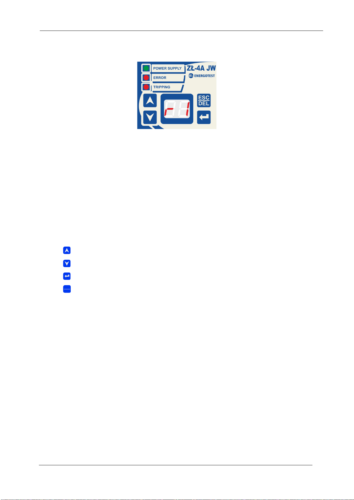
Fig. 4 Front panel of an executive unit ZŁ-4A JW.
Front panel of an executive unit is equipped with:
3 signaling LEDs:
•“POWER SUPPLY” – indicates the presence of power supply voltage,
•“ERROR” – indicates malfunctioning of the device,
•“TRIPPING” – indicates that unit has generated a tripping signal,
two digit seven segment LED display –indicates a state of the executive unit, allows
one to change a configuration of the unit,
4 buttons –for operation of the panel control:
UP –increasing the value,
DOWN –decreasing the value,
ENTER –settings approval, enter into menu mode,
ESC /DEL –tripping reset, menu mode exit.
ESC
KAS
Operating Manual
20
Arc fault protection ZŁ-4A; (07.2019)
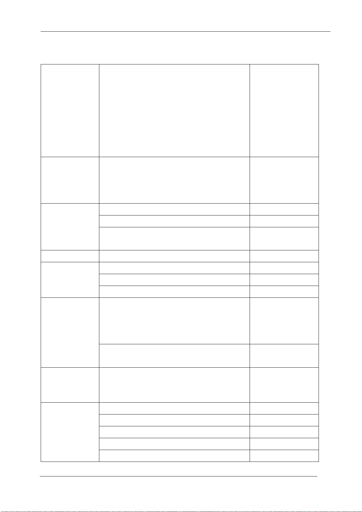
6. Technical data
Central unit
Measurement
voltage
Rated voltage Un
Continuous thermal withstand value
Thermal withstand value defined for 10 sec
Power consumption
Factory setting of voltage
for 3-phase short-circuit
Accuracy class
Measurement circuit separation
100 V, 50Hz
1.5 Un
2.5 Un
< 0.5 VA
0.7 Un
5%
2 kV
Auxiliary
voltage
Rated voltage Upn
Operating range of voltage
Max voltage level
Power consumption
24 V DC
0.8...1.1 Upn
1.3 Upn (perm)
6 W
Outputs Relay
tripping and
signaling
Max contact voltage
440 V AC; 250 V DC
Max continuous current
Max power AC1
8 A
2000 VA
Time
Up to the contact closing
< 8 ms
Insulation
electrical
Circuit insulation rated voltage
250 V
Electrical strength of insulation
2 kV/ 50 Hz /1 min
Between opened relay contacts
500 V/ 50 Hz/1 min
Environmental
conditions
Rated temperature
Temperature limits
Humidity
Atmospheric pressure
-10 ... +55 o C
-25 and +70 oC
45 ... 75 %
86 ...106 kPa
Vibrations endurance
1st class PN-EN
60255-21-1
Electromagnetic
compatibility
(EMC)
Test class
Max time of supply voltage interruption
III
20 ms
Casing
To be mounted on a rail TS-35 type RAILTEC C
Dimensions
159 / 90 / 58 mm
Weight
Approx. 0.42 kg
Degree of protection
IP20
clamps
Terminal block
Table of contents


