LOVATO ELECTRIC RGK30 User manual

Doc: I122IGB11_02.doc p. 1 / 7
RGK30 RGK30
Protezione motore Engine protection
MANUALE OPERATIVO INSTRUCTIONS MANUAL
Introduzione
L’ “RGK30” è un dispositivo per protezione motori ed è utilizzato per
l’avviamento e l’arresto di motori diesel o benzina. L’RGK30 provvede al
controllo ed allo spegnimento del motore in caso di guasto ed è dotato
delle seguenti protezioni: bassa pressione olio, alta temperatura motore ,
basso livello combustibile, avaria alternatore carica-batteria e alta e
bassa velocità del motore. L’RGK30 può essere facilmente adattato a
molti tipi di motore che utilizzano differenti alternatori carica-batteria
Introduction
The “RGK30” is a control unit for engine protection and is used for
manual starting and stopping of petrol (gasoline) or diesel engines.
The RGK30 provides for automatic monitoring and shutdown of the
engine in case of a fault and has protections for: low oil pressure, high
engine temperature, low fuel level, battery-charger alternator fault, low
and high engine speed. The “RGK30” can be easily adapted to many
engine types with different battery chargers alternator.
Descrizione frontale e funzionamento dei led
Tasti P1 e P2- Pulsanti di programmazione.
Front panel description and LED operation
P1 / P2 keys- Programming keys.
Led “Supply”
Acceso fisso all’alimentazione.
1 lampeggio al rilevamento di motore in moto.
Dopo il tempo “Ritardo abilitazioni allarmi” lampeggia ad indicare che gli
allarmi sono attivi.
Lampeggio veloce in fase d’arresto.
“Supply” LED
Constantly switched on at power up.
1 flash at motor running detection.
After the “Alarm enable delay”, flashes to indicate all alarms are working.
Quick flashing during stopping cycle.
Led Deceleratore / Candelette
All’alimentazione il led è acceso fisso ad indicare l’apertura
dell’elettrovalvola (spento in fase d’arresto).
Se K1 è impostato come Magnete d’arresto, dopo l’alimentazione il led
rimane spento (acceso in fase di arresto).
Lampeggiante ad indicare il trascorrere del tempo di preriscaldo candelette o
deceleratore.
Deceleration / Glow plugs LED
A
t power up the LED is constantly switched on to indicate the solenoid
valve opening (switched off during stopping cycle).
If K1 is programmed as Stop Magnet then, after power up, the LED
remains off (switched on during stopping cycle).
Flashing indicates the glow plug preheat or deceleration time lapsing.
Led Allarme fuori giri motore
Led Avaria alternatore carica-batteria
Prima di avviare il motore visualizzano lo stato dell’ingresso (solo se abilitati)
Spenti durante il corretto funzionamento del motore.
Accesi dopo l’arresto per allarme (solo se abilitati).
Engine out of limits alarm LED
Battery-charger alternator failure LED
Indicate the input state before the engine is switched on (if enabled only).
Switched off during normal engine operation.
Switched on after alarm stopping (if enabled only).
Led Allarme alta temperatura motore
Led Allarme basso livello carburante
Led Allarme bassa pressione olio
Prima di avviare il motore visualizzano lo stato dell’ingresso.
Spenti durante il corretto funzionamento del motore.
Accesi dopo l’arresto per allarme.
High engine temperature alarm LED
Low fuel level alarm LED
Low oil pressure alarm LED
Indicate the input state before the engine is switched on.
Switched off during normal engine operation.
Switched on after alarm stopping.
WARNING! Technical descriptions and data given in this
document are accurate, to the best of our knowledge, but can
be subject to change without prior notice so no liabilities fo
r
errors, omissions or contingencies arising therefrom are
accepted. Moreover, the RGK should be set up and used b
y
specialised personnel and, in any case, in compliance to
current installation standards, to avoid damages or safety
hazards.
ATTENZIONE!! Le descrizioni ed i dati contenuti in
questo manuale sono suscettibili in qualsiasi momento di
modifiche e non possono pertanto avere nessun valore
contrattuale. Si ricorda altresì che l’RGK30 deve essere
utilizzato da personale qualificato e comunque nel rispetto
delle vigenti normative impiantistiche di installazione e ciò allo
scopo di evitare danni a persone e cose.
I 122 I GB 11 02

Doc: I122IGB11_02.doc p. 2 / 7
Modo di funzionamento
Posizionando il selettore a chiave esterno sulla posizione “RUN” l’RGK30
viene alimentato. L’apparecchio esegue il test dei led al termine del quale
si predispone all’avviamento da effettuarsi mediante interruttore a chiave
esterno (posizione “START”).
Trascorso il tempo “Ritardo inibizione allarmi” le protezioni sono attive ed
in presenza di anomalia il dispositivo provvede all’arresto del motore.
Per procedere all’arresto riportare il selettore a chiave in posizione “OFF”.
Se, trascorsi 2 minuti dall’alimentazione, il motore non si è avviato viene
disalimentata l’elettrovalvola carburante e eccitato il relè “Allarme globale”
Per motori dotati di magnete d’arresto dovrà essere previsto un selettore
a chiave con posizione “STOP” sulla quale effettuare l’eccitazione del
solenoide.
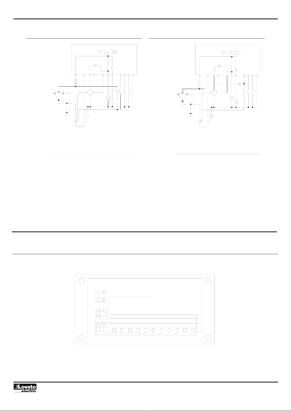
Per i collegamenti nelle varie soluzioni fare riferimento agli schemi
applicativi.
Operating mode
By turning the external selector key to the “RUN” position, the RGK30
is powered up. The engine control conducts a LED test cycle and then
it sets itself up for the starting cycle which is operated by turning the
key to “START”.
After the “Alarms inhibition delay”, the protections are enabled and, if
there are malfunction conditions, the unit stops the engine.
To proceed with the stopping cycle, turn the key to “OFF”.
If the engine is not started after 2 minutes from the power up, the fuel
solenoid valve is de-energised and the “Global alarm” relay is
energised.
A key selector switch with a “STOP” position is needed for engines
equipped with stop magnet, to consent to the solenoid energising.
Refer to the application wiring diagrams for connections in various
solutions.
Ingresso avviamento a distanza
Il funzionamento del motore tramite l’ingresso “Avviamento a distanza”
richiede, oltre al segnale di avviamento, che venga contemporaneamente
fornita alimentazione all’apparecchio (vedi schemi applicativi).
Se presenti le sopra citate condizioni la scheda esegue i tentativi di
avviamento. Il dispositivo provvede automaticamente, mediante il segnale
di motore avviato, allo stacco del motorino.
L’arresto avviene interrompendo la tensione all’ingresso e
all’alimentazione.
Remote starting input
The engine operation via “Remote starting” input requires the
simultaneous supply of the device (see application diagrams) along
with the starting signal.
If both are at hand, the unit can begin the starting attempts. It
automatically operates the starting motor disconnection via the engine
running signal.
Stopping is obtained by disconnecting the voltage at the input and supply.
Allarmi
Gli allarmi “Pressione, Temperatura e Livello combustibile” vengono
abilitati a motore avviato, al termine del ritardo inibizione allarmi.
L’allarme “Fuori giri” viene abilitato al rilevamento di motore in moto.
Se impostato il relè K1 come “Deceleratore”, l’intervento per bassi giri
motore viene abilitato allo scadere del tempo di decelerazione.
Con scheda alimentata e motore fermo o con ritardo inibizione allarmi
non scaduto, i led sul fronte visualizzano lo stato dell’ingresso senza
generare alcun allarme.
Durante il funzionamento del motore, il manifestarsi di un allarme ne
causa l’arresto. L’intervento viene memorizzato ed il led relativo all’avaria
rimane acceso. In questa condizione non vengono visualizzati ulteriori
allarmi ad eccezione di quello che ha causato l’arresto del motore.
Il ripristino avviene disalimentando l’apparecchio, oppure premendo un
tasto al termine del tempo di Stop.
Alarms
The “Pressure”, “Temperature” and “Fuel level” alarms are enabled
when the engine is running after the alarms inhibition delay . The
“RPM out of limits” alarm is enabled when engine running is detected.
If the K1 relay is set as “Decelerator”, the low engine rpm tripping is
enabled at the deceleration time lapsing.
With the unit supplied and the engine stopped or the alarms inhibition
time not lapsed, the front LEDs show the input state, without causing
any alarm event.
While operating, the engine will be stopped at any alarm event. The
tripping is stored and the relative malfunction LED remains switched
on. In these conditions, no other alarm is displayed except for the one
causing the engine to stop.
Resetting is obtained by removing power from the unit or by pressing
any of the keys at the lapsing of the Stop time.
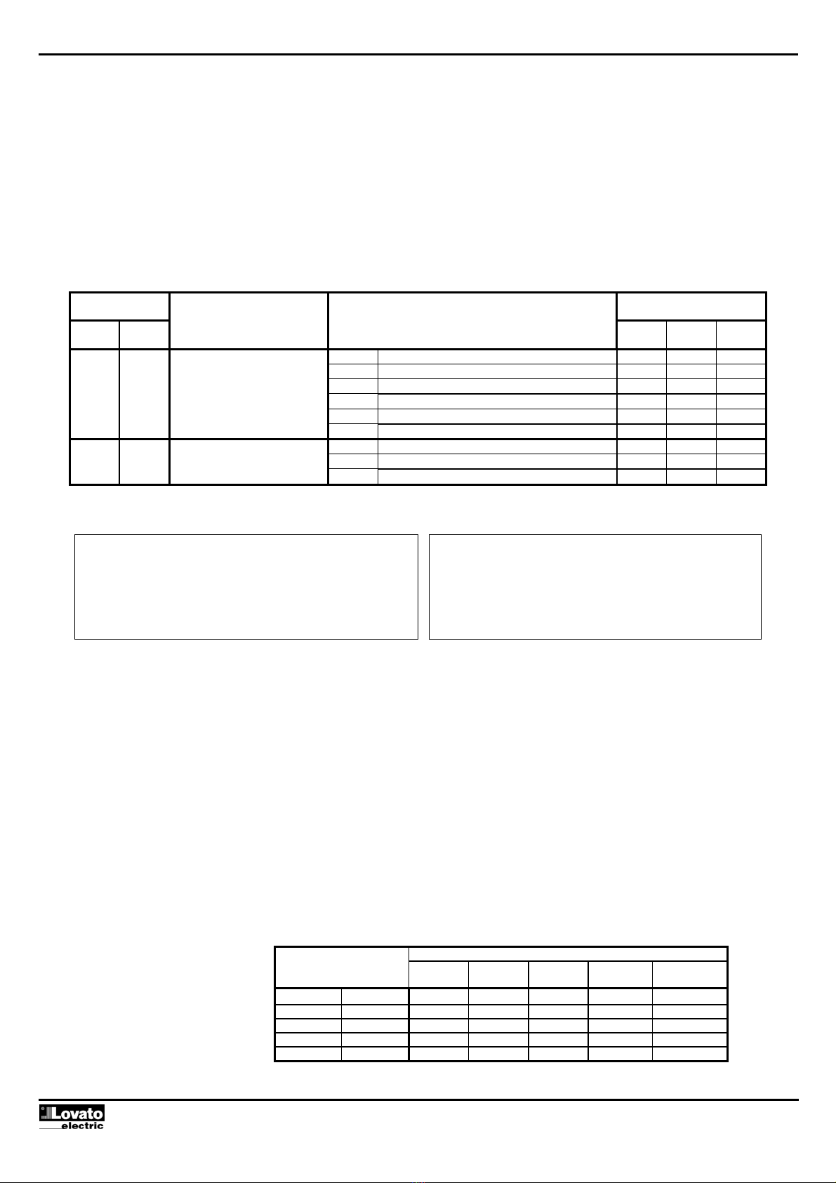
Descrizione Default Description
Tempo inibizione allarmi 8s Alarms inhibition time
Ritardo abilitazione allarme alta velocità motore 0,5s High engine rpm alarm enabling delay
Ritardo intervento alta velocità motore 0,5s High engine rpm tripping delay
Ritardo abilitazione allarme bassa velocità motore 8s Low engine rpm alarm enabling delay
Ritardo intervento bassa velocità motore 5s Low engine rpm tripping delay
Ritardo intervento allarme carburante 10s Fuel alarm tripping delay
Ritardo allarme D+ 2s D + alarm delay
Tempo magnete d’arresto 25s Stop magnet time
Tempo decelerazione 30s Deceleration time
Tempo candelette 10s Glow plugs time
Durata tentativi di avviamento 5s Starting attempts duration
Pausa tentativi di avviamento 10s Starting attempts pause time
Tentativi di avviamento 5 Starting attempts
Soglia motore avviato D+ 8VDC Running engine D+ voltage threshold
Soglia motore avviato AC 10VAC Running engine AC voltage threshold
Ritardo allarme mancata partenza 120s Starting failure alarm delay
Durata stop a impulso 2s Pulse stop duration

Doc: I122IGB11_02.doc p. 3 / 7
Impostazione parametri
Per accedere manualmente al setup premere P2 per 3 secondi prima
che gli allarmi siano inseriti. L’ingresso nel Setup e’ segnalato dai due
led verdi lampeggianti.
Premendo P1 si incrementa il valore del parametro.
Premendo P2 si procede alla scelta del parametro.
E’ possibile impostare due parametri:
Scelta funzione rele’ K1 (morsetto 3): Allarme globale / candelette /
deceleratore / Avviamento / Magnete d’arresto / Stop a impulso
Abilitazione Allarmi : Solo D+ / Solo W / Entrambi
Per indicare quale parametro e’ selezionato vengono utilizzati i led RPM
e TEMPERATURA (lampeggianti).
Per indicare a che valore e’ impostato il parametro vengono utilizzati i
led FUEL, OIL e D+ (fissi).
Premere P2 per salvare.
Parameters setup
To have manual access to the setup, press P2 for 3 seconds before
the alarms are enabled. The Setup entry is indicated by the two
flashing green LEDs.
Press P1 to increase the parameter value.
Press P2 to proceed to the parameter choice.
Two parameters can be setup:
K1 relay (terminal 3) function choice: Global alarm / Glow plugs /
Deceleration / Starting / Stop magnet / Pulse stop
Alarms enabling: D + only / W only / Both.
To show which parameter has been selected, the RPM and
TEMPERATURE LEDs are used and flashing.
To show the value at which the parameter has been set, the FUEL,
OIL and D + LEDs are used and constantly switched on.
Then press P2 to save.
SELEZIONE
CHOICE IMPOSTAZIONE / SETTING
LED
RPM
LED
TEMP
PARAMETRO SELEZIONATO
PARAMETER SELECTED
FUNZIONE IMPOSTATA
FUNCTION SETUP LED
FUEL
LED
OIL
LED
D+
Default ALLARME GLOBALE / GLOBAL ALARM ●❍❍
CANDELETTE / GLOW PLUGS ❍●❍
DECELERATORE / DECELERATION ●●❍
AVVIAMENTO / STARTING ❍❍●
MAGNETE ARRESTO / STOP MAGNET ●❍●
✸❍
FUNZIONE RELE’ K1
(MORSETTO 3)
K1 RELAY (TERMINAL 3)
FUNCTION CHOICE
STOP A IMPULSO / PULSE STOP ❍●●
Default SOLO D+ ABILITATO / D + ENABLED ONLY ●❍❍
SOLO RPM ABILITATO / RPM ENABLED ONLY ❍●❍
❍✸ABILITAZIONE ALLARMI
ALARMS ENABLING D+/RPM ABILITATI / BOTH ENABLED ●●❍
❍= LED SPENTO / LED SWITCHED OFF
●= LED ACCESO / LED SWITCHED ON
✸= LED LAMPEGGIANTE / LED FLASHING
NOTA:
Se si abilita il controllo giri motore ma non viene eseguita
l’acquisizione della frequenza, il led RPM lampeggia
continuamente.
Per reimpostare a default i parametri mantenere premuto
all’alimentazione i tasti P1 e P2. Attendere che led “Supply”
lampeggi, quindi rilasciare P1 e P2.
NOTE:
If the engine rpm control is enabled but the frequency acquisition
is not conducted then the RPM LED continuously flashes.
To reset the parameters to default, keep P1 and P2 keys
pressed after power up and wait until the “Supply” LED flashes.
Then release the two keys.
Acquisizione dei giri motore nominali attraverso segnale “W / AC”
L’acquisizione è necessaria solo se l’allarme RPM è abilitato.
Per fare acquisire la frequenza nominale all’apparecchio, premere
contemporaneamente i tasti P1 e P2 per 3 secondi con motore in moto.
L’ingresso nella procedura di acquisizione viene evidenziato dal
lampeggio dei led SUPPLY e D+.
Con il motore che gira regolarmente, premere P1 per dare inizio alla
acquisizione dei valori.
Durante la lettura i led TEMP e FUEL lampeggiano alternativamente.
Se il sistema ha rilevato la frequenza, si accende il led verde
elettrovalvola fisso.
Se invece non viene rilevata alcuna frequenza oppure viene letta una
frequenza troppo elevata, tutti i led lampeggeranno velocemente.
Premere P2 per resettare e poi P1 per ripetere l’acquisizione.
Una volta terminata l’acquisizione si passa a definire i limiti di deviazione
massima dalla frequenza nominale.
Premendo P2 per passare all’impostazione della tolleranza sul numero
di giri.
Premere P1 per scegliere il valore.
Premere P2 per salvare.
Rated engine RPM acquisition via “W /AC” signal
Acquisition is required only if the RPM alarm is enabled.
To acquire the rated frequency value of the unit, simultaneously press
P1 and P2 keys for 3 seconds with the engine running.
The acquisition procedure entry is displayed by the SUPPLY and D +
LEDs flashing.
With the engine normally running, press P1 to begin the value
acquisition.
During acquisition, the TEMP and FUEL LEDs are alternately flashing.
If the system detects the frequency value, the green solenoid valve
LED is constantly switched on.
Otherwise, all LEDs rapidly flash denoting no frequency value is
detected or a too high frequency value is acquired. Press P2 to reset
and then P1 to repeat acquisition.
After this operation is ended, the maximum variation limit of the rated
frequency is next to be defined.
Push P2 to proceed to the tolerance setting of the engine rpm.
Press P1 to select the value.
Then press P2 to save.
IMPOSTAZIONE / SETTING
DEVIAZIONE MAX
MAX VARIATION LED
RPM
LED
TEMP
LED
FUEL
LED
OIL
LED
D+
+/- 10%
❍❍❍❍●
+/- 15%
❍❍❍●●
Default +/- 20% ❍❍●●●
+/- 25%
❍●●●●
❍= LED SPENTO / LED SWITCHED OFF
●= LED ACCESO / LED SWITCHED ON
+/- 30%
●●●●●

Doc: I122IGB11_02.doc p. 4 / 7
Schemi di connessione Wiring diagrams
Schema di collegamento per motore con alternatore carica-
batteria preeccitato
Wiring diagram for engine with pre-excited battery charger
alternator
Schema di collegamento per motore con alternatore carica-
batteria a magneti permanenti
Wiring diagram for engine with permanent magnet battery
charger alternator
Schema di collegamento per motore con magnete d’arresto
Wiring diagram for engine with stop magnet
ALLARME GLOBALE / DECELERATORE
12 O 24VDC
ELETTROVALVOLA CARBURANTE
GLOBAL ALARM / DECELERATOR
BOSCH, MARELLI, LUCAS,....
FUEL SOLENOID VALVE
ENGINE TEMPERATURE
ALTERNATOR TYPE
12 OR 24VDC
BATTERY
"W" SPEED INPUT
GLOW-PLUGS
OIL PRESSURE
FUEL LEVEL
MOTORINO AVVIAMENTO
OFF
RUN
START
11
K1
ALTERNATORI TIPO
BOSCH, MARELLI, LUCAS,...
INGRESSO VELOCITA' "W"
BATTERIA
CANDELETTE
LIVELLO CARBURANTE
TEMPERATURA MOTORE
PRESSIONE OLIO
G
+B W
+D
62 1 78
K2
34 95 10
STARTING MOTOR
INTERRUTTORE A CHIAVE ESTERNO
EXTERNAL KEY SWITCH
+B
12 O 24VDC
STARTING MOTOR
12 OR 24VDC
BATTERY
MOTORINO AVVIAMENTO
BATTERIA
OFF
RUN
START
2 1
ALLARME GLOBALE / DECELERATORE
ELETTROVALVOLA CARBURANTE
GLOBAL ALARM / DECELERATOR
FUEL SOLENOID VALVE
ENGINE TEMPERATURE
GLOW-PLUGS
"W" SPEED INPUT
ALTERNATOR TYPE
DUCATI, SAPRISA.....
FUEL LEVEL
OIL PRESSURE
GK1
CANDELETTE
ALTERNATORI TIPO
DUCATI, SAPRISA,...
INGRESSO VELOCITA' "W"
LIVELLO CARBURANTE
TEMPERATURA MOTORE
PRESSIONE OLIO
C
K2
6748 3105 9 11
INTERRUTTORE A CHIAVE ESTERNO
EXTERNAL KEY SWITCH
12 O 24VDC
ALTERNATOR TYPE
STOP MAGNET
BATTERY
12 OR 24VDC
STARTING MOTOR
ENGINE TEMPERATURE
"W" SPEED INPUT
STOP MAGNET
DUCATI, SAPRISA.....
OIL PRESSURE
FUEL LEVEL
G
ALTERNATORI TIPO
K1
MAGNETE D'ARRESTO
MOTORINO AVVIAMENTO
BATTERIA
EXTERNAL KEY SWITCH
START
INTERRUTTORE A CHIAVE ESTERNO
STOP
OFF
RUN
+B
21 6
K1
TEMPERATURA MOTORE
MAGNETE D'ARRESTO
INGRESSO VELOCITA' "W"
DUCATI, SAPRISA,...
PRESSIONE OLIO
LIVELLO CARBURANTE
C
4
783 5 10911

Doc: I122IGB11_02.doc p. 5 / 7
Schema di collegamento con avviamento a distanza mediante
interruttore bipolare
Wiring diagram for remote starting with two-pole switch
Schema di collegamento con avviamento a distanza mediante
interruttore e diodo
Wiring diagram for remote starting with switch and diode
*
Il diodo deve essere dimensionato con una corrente almeno doppia alla
somma dei valori risultanti dai seguenti dati:
The diode must be rated twice the total value resulting from the sum of the
following data:
Correnti uscite morsetti 3 e 4
Assorbimento apparecchio
Corrente eccitazione o alimentazione alternatore CB
Output current values at terminals 3 and 4
Unit consumption
Energising current or BC alternator supply
N.B. Prevedere eventualmente un dissipatore per il diodo. N.B. Eventually use a dissipater for the diode.
Connessioni morsettiere (vista dal retro) Terminal block connections (rear view)
ELETTROVALVOLA CARBURANTE
BOSCH, MARELLI, LUCAS,....
STARTING MOTOR
BATTERY
12 OR 24VDC
ALTERNATOR TYPE
OIL PRESSURE
ENGINE TEMPERATURE
"W" SPEED INPUT
FUEL SOLENOID VALVE
START RELAY
FUEL LEVEL
INTERRUTTORE A CHIAVE ESTERNO
MOTORINO AVVIAMENTO
ALTERNATORI TIPO
BOSCH, MARELLI, LUCAS,...
BATTERIA
12 O 24VDC
K1
OFF
EXTERNAL KEY SWITCH
RUN
START
G
+D
+B W
216
7
PRESSIONE OLIO
INGRESSO VELOCITA' "W"
AVVIAMENTO A DISTANZA
TEMPERATURA MOTORE
RELE' AVVIAMENTO
LIVELLO CARBURANTE
K1
K2
348 95 10 11
REMOTE STARTING
8
INGRESSO VELOCITA' "W""W" SPEED INPUT
BOSCH, MARELLI, LUCAS,....
STARTING MOTOR
ALTERNATOR TYPE
12 OR 24VDC
BATTERY
INTERRUTTORE A CHIAVE ESTERNO
MOTORINO AVVIAMENTO
BOSCH, MARELLI, LUCAS,...
ALTERNATORI TIPO
12 O 24VDC
BATTERIA
K1
RUN
EXTERNAL KEY SWITCH
OFF
START
G
+B W
+D
12 7
6
ELETTROVALVOLA CARBURANTE
FUEL LEVEL
START RELAY
FUEL SOLENOID VALVE
ENGINE TEMPERATURE
OIL PRESSURE
LIVELLO CARBURANTE
RELE' AVVIAMENTO
AVVIAMENTO A DISTANZA
TEMPERATURA MOTORE
PRESSIONE OLIO
11
*
K2
K1
43 1059
REMOTE STARTING
24V
12V
battery charger set-up
811 10 9
Pre-excited
5674312
Supply
+--

Doc: I122IGB11_02.doc p. 6 / 7
Caratteristiche tecniche Technical characteristics
Alimentazione ausiliaria Auxiliary supply
Tensione nominale di batteria 12 o 24VDC indifferentemente Rated battery voltage 12 or 24VDC indifferently
Campo di funzionamento 9÷33VDC Voltage range 9…33VDC
Tensione minima all’avviamento 6,7VDC Minimum voltage at the starting 6.7VDC
Limite abbassamento tensione
all’avviamento
4VDC for 150ms Cranking drop-out 4VDC for 150ms
Corrente massima assorbita 70mA a 12VDC
90mA a 24VDC
110mA a 33VDC
Maximum current consumption 70mA at 12VDC
90mA at 24VDC
110mA at 33VDC
Potenza massima assorbita 3,6W 33VDC Maximum power consumption 3.6W 33VDC
Potenza massima dissipata 3,6W 33VDC Maximum power dissipated 3.6W 33VDC
Immunità alle micro interruzioni 200ms Immunity at micro breakings 200ms
Ingressi digitali Pressione, Temperatura e Combustibile Pressure, Temperature and Fuel level digital inputs
Tipo d’ingresso negativo Input type Negative
Corrente d’ingresso ≤4mA a 12V e ≤8mA a 24V Current input ≤4mA at 12V and ≤8mA at 24V
Segnale d’ingresso basso ≤1,5V (tipico 2,9V) Input “low” voltage ≤1.5V (typical 2.9V)
Segnale d’ingresso alto ≥5,3V (tipico 4,3V) Input “high” voltage ≥5.3V (typical 4.3V)
Ritardo del segnale d’ingresso 1s Input delay 1s
Ingresso digitale Avviamento a distanza Remote starting digital input
Tipo d’ingresso Positivo Input type Positive
Corrente d’ingresso ≤4mA a 12V e ≤8mA a 24V Current input ≤4mA at 12V and ≤8mA at 24V
Segnale d’ingresso basso ≤1,5V (tipico 2,9V) Input “low” voltage ≤1.5V (typical 2.9V)
Segnale d’ingresso alto ≥5,3V (tipico 4,3V) Input “high” voltage ≥5.3V (typical 4.3V)
Ritardo del segnale d’ingresso 1s Input delay 1s
Ingresso 500giri alternatore carica batteria a magneti permamenti o
segnale “W”
Engine running input (500 rpm) for permanent magnet alternator or “W”
signal
Tipo d’ingresso Accoppiamento AC Input type AC coupling
Campo di tensione 5÷40VAC Voltage range 5…40VAC
Campo di frequenza 40÷2000Hz Frequency range 40…2000Hz
Ingresso 500giri alternatore carica batteria pre-eccitato Engine running input (500rpm) for pre-excited alternator
Campo di funzionamento 0÷40VDC Voltage range 0…40VDC
Tensione massima al terminale
“D+”
12 or 24VDC da batteria ( mediante
impostazione jumper)
Maximum voltage at D+ terminal 12 or 24VDC battery voltage (prior
jumper positioning)
Corrente di pre-eccitazione 170mA 12VDC - 130mA 24VDC Pre-excitation current 170mA 12VDC - 130mA 24VDC
Uscite a relè (Uscite in tensione + batteria) Relay outputs (+ battery voltage outputs)
Tipo di contatto 1 NO Contact type 1 NO
Dati d’impiego UL / IEC B300 / 0.5A 30VDC serv. ausiliario / DC13 UL / IEC rating B300 / 0.5A 30VDC Pilot Duty / DC13
Tensione d’impiego 30VDC Rated voltage 30VDC
Portata nominale a 30VDC 5A DC1 Rated current at 30VDC 5A DC1
Condizioni ambientali di funzionamento Ambient conditions
Temperatura d’impiego -20÷+60°C Operating temperature -20…+60°C
Temperatura di stoccaggio -30÷+80°C Storage temperature -30…+80°C
Umidità relativa <90% Relative humidity <90%
Inquinamento ambiente massimo Grado 2 Maximum pollution degree 2
Connessioni Connections
Tipo di morsetti Estraibili Type of terminals Plug-in
Sezione conduttori (min e max) 0,2÷2,5 mmq (24÷12 AWG) Cable cross section (min… max) 0.2…2.5 mm² (24 / 12 AWG)
Coppia di serraggio 0,5 Nm (4,5 Lb in) Tightening torque 0.5 Nm (4.5 lb in)
Contenitore Housing
Esecuzione Da incasso Version Flush mount
Dimensioni 96x48x106mm Dimensions 96x48x106mm
Foratura 91x45mm Panel cutout 91x45mm
Materiale Noryl nero autoestinguente Material Self extinguishing black Noryl
Grado di protezione frontale IP41 frontale; IP20 morsetti Degree of protection IP41 on front; IP20 terminals
Peso 160g Weight 160g
Norme di riferimento Reference standards
IEC/EN 60255-6, IEC/EN 61000-4-2, IEC/EN 61000-4-3, IEC/EN 61000-4-4,
IEC/EN 61000-4-5, IEC/EN 61000-4-6, IEC/EN 55011, IEC/EN 60028-2-61,
IEC/EN 60068-2-6 (LROS-Lloyd’s Register Of Shipping), IEC/EN 60068-2-27,
IEC/EN 61010-1, EN 50082-2, UL 508 e C22.2_14-M95
IEC/EN 60255-6, IEC/EN 61000-4-2, IEC/EN 61000-4-3, IEC/EN 61000-4-4,
IEC/EN 61000-4-5, IEC/EN 61000-4-6, IEC/EN 55011, IEC/EN 60028-2-61,
IEC/EN 60068-2-6 (LROS-Lloyd’s Register Of Shipping), IEC/EN 60068-2-27,
IEC/EN 61010-1, EN 50082-2, UL 508 and C22.2_14-M95
Omologazioni Certifications
cULus cULus
UL “Marking”
• Montaggio su superfice piana in contenitore "Type 1"
• Utilizzare conduttore di rame (CU) 60°C/75°C e con sezione da 18/12
AWG, flessibile o rigido
• Questo apparecchio deve essere protetto, sull’alimentazione da batteria,
da Fusibile certificato “UL Listed”, del tipo a uso generale, miniaturizzato
o micro (JDYX) da 4A.
UL Marking
• “For Use on a Flat surface of a Type 1 Enclosure”
• "Use 60°C/75°C copper (CU) conductor and wire size range 18-12 AWG,
stranded or solid"
• “These Devices shall be protected by Any Listed Fuses, Miscellaneous,
Miniature and Micro (JDYX) 4 A Fuses on battery supply”

Doc: I122IGB11_02.doc p. 7 / 7
Dimensioni d’ingombro e foratura [mm] Overall dimensions and panel cutout [mm]
Table of contents
Other LOVATO ELECTRIC Protection Device manuals