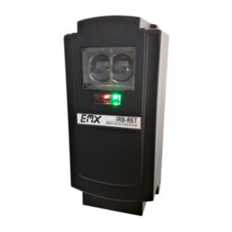
EMX PhotoeyeVault User manual

EMX Industries, Inc. Tech support: 216-518-9889 1/8
PhotoeyeVault_Rev1.0_112520 [email protected]
PhotoeyeVault™
Protection Bollard
Instruction Manual
The PhotoeyeVault is a security-style bollard that protects photoeyes and provides
a stylish alternative to visible hardware. Keep photoeyes safe from vandalism, inclement weather,
and accidental contact damage with this solid steel fixture. The PhotoeyeVault hides electronics
while blending in with the surroundings. It is compatible with EMX IRB-RET, EMX IRB-MON, and
EMX IRB-4X photoeyes.
Contents
A. PhotoeyeVault Kit Parts
Page 2
B. Tools and Materials for Field Installation
Page 3
C. Prerequisites to Installing the PhotoeyeVault
…….......................................................................
Page 3
D. Installation Steps
…................................................................................................
.......................
Page 5
Step 1: Unbox PhotoeyeVault Kit
Page 5
Step 2: Mount Photoeye* and PhotoeyeVault
Page 5
Step 3: Connect Wiring
Page 7
Step 4: Aim PhotoeyeVault
Page 8
Step 5: Conclude the Installation
Page 8
*EMX photoeye sold separately
Cautions and Warnings
This product is an accessory or part of a system. Install the EMX PHOTOEYE (IRB-RET,
IRB-MON, or IRB-4X) according to instructions from the gate or door operator manufacturer.
Comply with all applicable codes and safety regulations.
Specifications
Housing Material
.120” 11-gauge steel post
1/8” steel base plate
Up to 115 ft (35 m)
Dimensions
4.25” x 4.25” x 24.25” post
8 x 8” base plate
ononly)
Finish
Black powder coat
Weight
16 lbs
TM

EMX Industries, Inc. Tech support: 216-518-9889 2/8
PhotoeyeVault_Rev1.0_112520 [email protected]
Ordering Information
•PhotoeyeVault Protection bollard *photoeye sold separately
•IRB-RET KIT UL325 Retroreflective photoeye kit, includes photoeye with hood,
reflector with hood, and mounting bracket with hardware
•IRB-MON KIT UL325 Thru beam photoeye kit, includes transmitter, receiver, protective
hoods, and sunshield
•IRB-4X KIT Thru beam photoeye kit, includes transmitter, receiver, protective hoods,
and sunshield
A. PhotoeyeVault Kit Parts
A
IRB-MON / IRB-4X Thru Beam Photoeye*
B
IRB-RET Retroreflective Photoeye*
*EMX photoeye sold separately (NOT INCLUDED IN KIT)
Fig A: PhotoeyeVault Kit
Part
Description
Qty
1
PhotoeyeVault Front Cover
1
2
Front Cover Screws
8
3
5/32” Hex Head Bit
1
4
Front Cover Knock-out Hole
1
5
PhotoeyeVault Backplate
1
6
Attachment Screws for IRB-MON / IRB-4X
4

EMX Industries, Inc. Tech support: 216-518-9889 3/8
PhotoeyeVault_Rev1.0_112520 [email protected]
B. Tools and Materials for Field Installation (by installer/customer)
•Security screw bit (included in kit)
•Open end and socket wrench set
•Standard hand tools (screwdriver set, longnose pliers, etc...)
•Allen wrench set
•Ballpeen hammer
•Power drill and bit sets (for wood, concrete, steel)
•Wire nuts or caps
•Wire ties
C. Prerequisites to Installing the PhotoeyeVault
C.1 Customer/contractor is responsible for the following items to be ready at the site ahead of
installation of the PhotoeyeVault
C.1.1 Concrete mounting pad with minimum specifications of 14" diameter x 12" deep
TORXUN recommends use of cylindrical footing (see drawing inset in Fig C.1)
C.1.2 Rigid conduit 3/4” diameter running up through the center of the concrete pad extending to
about 12" off the pad surface; conduit runs buried under the pavement between the gate
operator and the pad; Fig C.1 (consult local electrical code for buried conduits)
C.1.3 Pull enough length of wires through the conduit to connect the photoeyes to the gate operator
in final installation steps
Power wire specifications: 12-24 VDC capacity, #18 wire, 2 wires
Control & signal wires specification: #18 wire, 2 wires
All wires to be routed through the conduit described in item C.1.2
Fig C.1: Installation Schematics
Torxun recommends the use of cylindrical concrete footing for ease and symmetry of aiming the
PhotoeyeVault and the photoeye across the drive path (see inset).

EMX Industries, Inc. Tech support: 216-518-9889 4/8
PhotoeyeVault_Rev1.0_112520 [email protected]
C.2 The PhotoeyeVault, with the photoeye in it, is installed and typically positioned a few inches before
the vehicle gate line such that the photoeye transmitter projects a beam across the opening of the
vehicle gate to the receiver or reflector.
Note: The photoeye is aimed directly to the receiver or reflector across the other end of the gate
with the projected beam parallel to the gate opening cutting through the vehicle drive path.
Fig C.2: PhotoeyeVault / Photoeyes as Obstruction Sensors
Fig C.3: (Plan View) PhotoeyeVault / Photoeyes as Obstruction Sensors

EMX Industries, Inc. Tech support: 216-518-9889 5/8
PhotoeyeVault_Rev1.0_112520 [email protected]
D. Installation Steps
Step 1 –Unbox the PhotoeyeVault Kit
Note: The EMX photoeyes are sold separately; they are not part of the kit
•Remove the PhotoeyeVault from the product box
•Check each item referring to section A –the kit parts list
Step 2 –Mount the Photoeye and PhotoeyeVault
2.1 IRB-MON / IRB-4X Photoeye (for IRB-RET see 2.2)
The IRB-MON / IRB-4X has both the Transmitter and the Receiver unit.
The steps to attach the units to the PhotoeyeVault are the same.
2.1.1 Mount the IRB-MON / IRB-4X Photoeye to the PhotoeyeVault
•Loosen and remove the PhotoeyeVault body screws (8 screws), set screws aside
•Remove the backplate of the PhotoeyeVault
•There are four (4) base pegs on the inside face of the backplate where the photoeye
must be mounted
•Remove the front acrylic cover of the IRB-MON / IRB-4X unit
•Remove the knock-out cover at the bottom of the photoeye housing
•Center the photoeye housing to the four base pegs inside the PhotoeyeVault backplate
•Use the four (4) screws (included in the kit) to attach the photoeye housing to the
respective base pegs on the backplates
•Set aside the backplate with the attached photoeye
2.1.2 Mount the PhotoeyeVault on the Footing Pad
•Move the PhotoeyeVault front cover over the footing pad
•Sit the front cover down on the concrete footing (pad) passing the conduit and wires
through the baseplate access hole, (Fig 2.3 next page)
•Proceed to Step 3.1
2.2 IRB-RET Photoeye
The IRB-RET is a retroreflective photoeye. It requires a
reflector across the monitored distance to reflect back
the photoeye beam.

EMX Industries, Inc. Tech support: 216-518-9889 6/8
PhotoeyeVault_Rev1.0_112520 [email protected]
2.2.1 Mount the IRB-RET Photoeye to the PhotoeyeVault
•Loosen and remove the PhotoeyeVault body screws (8 screws), set screws aside
•Remove the backplate of the PhotoeyeVault
•The IRB-RET comes with a mounting bracket of its own
•There are two (2) base pegs on the inside face of the front cover where the photoeye
bracket must be mounted
•Use the two (2) screws with nuts (included with the IRB-RET unit) to mount the bracket
•Follow the instructions in the EMX manual to install the IRB-RET unit to the bracket
•Follow the instructions in the EMX manual to install the reflector at the opposite side of
the sensing zone
•Proceed to Step 3.2
2.2.2 Mount the PhotoeyeVault on the Footing Pad
•Move the PhotoeyeVault front cover over the footing pad
•Sit the front cover down on the concrete footing (pad) passing the conduit and wires
through the baseplate access hole, (Fig 2.3 below)
•Proceed to Step 3.2
Fig 2.3 Front Cover Over Conduit & Footing

EMX Industries, Inc. Tech support: 216-518-9889 7/8
PhotoeyeVault_Rev1.0_112520 [email protected]
Step 3 –Connect Wiring to the Photoeye
3.1 IRB-MON / IRB-4X Photoeye (for IRB-RET see 3.2)
Note: Installations where the conduit is not embedded in the pad, photoeye wires can
be coursed through a knock-out access hole located at the side face of the front cover
of the PhotoeyeVault. (See Fig A –Part #4)
•Refer to the wiring guide in the EMX manual for wiring the IRB-MON / IRB-4X photoeye
•Check to see that power to the gate operator and photoeyes is switched off
•Move the PhotoeyeVault backplate near the footing pad
•Thread enough length of the wires from the conduit through the knock-out hole of the
photoeye housing
•Connect the corresponding wiring to the proper terminals on the IRB-MON / IRB-4X
following directions in the EMX manual
•Coil up the remaining wire slack under the photoeye housing, secure with electrical
tape or wire-ties
•Assemble the backplate to the front cover and secure with screws (8x)
•Proceed to Step 4.1
3.2 IRB-RET Photoeye
Note: Installations where the conduit is not embedded in the pad, photoeye wires can
be coursed through a knock-out access hole located at the side face of the front cover
of the PhotoeyeVault. (See Fig A –Part #4)
•Refer to the wiring guide in the EMX manual for wiring the IRB-RET photoeye
•Check to see that power to the gate operator and photoeyes is switched off
•Thread enough length of the wires from the conduit through the bracket and the
IRB-RET housing
•Connect the appropriate wiring to the proper terminals on the back side of the IRB-RET
following directions in the EMX manual
•Coil up the remaining wire slack under the bracket and secure with electrical tape or
wire-ties
•Proceed to Step 4.2
Instructions continue on next page
Step 4 –Aim the PhotoeyeVault

EMX Industries, Inc. Tech support: 216-518-9889 8/8
PhotoeyeVault_Rev1.0_112520 [email protected]
4.1 IRB-MON / IRB-4X Photoeye (for IRB-RET see 4.2)
•At the operator side, connect all wiring to the gate operator terminals following the
EMX wiring diagram for the IRB-MON / IRB-4X
•Conduct safety checks before restoring power to the gate operator and the gate system
•Switch power back on the gate operator/system
•Having both PhotoeyeVaults over their respective footing pads, proceed to aim the
photoeyes across to each other
•Conduct a series of aim and test to ensure proper operation of the photoeyes; follow
aiming instructions in the EMX manual for IRB-MON / IRB-4X
•Upon successfully aiming the transmitter and receiver pair, mark the position on the
respective base plates of the PhotoeyeVaults and corresponding pads
4.2 IRB-RET Photoeye
•At the operator side, connect all wiring to the gate operator terminals following the
EMX wiring diagram for the IRB-RET
•Conduct safety checks before restoring power to the gate operator and the gate system
•Switch power back on the gate operator/system
•Follow the instructions in the EMX manual to program and calibrate the IRB-RET
•Conduct a series of aim and test to ensure proper operation of the photoeye as per
instructions in the EMX manual
•Upon successfully aiming the emitter unit and reflector pair, mark the position on the
base plate of the PhotoeyeVault
Step 5 –Conclude the Installation
•To each PhotoeyeVault baseplate, drill the first mounting hole using the baseplate as a jig,
referencing the position markers established earlier in the process
•Conduct a round of final tests on the photoeyes to ensure correct aim
•Adjust aims accordingly if values deviate from suggested readings
•Mark the second mounting hole on the baseplate(s); drill and slip-in the mounting hardware
and tighten
•Proceed to mark and drill the remaining third and fourth mounting holes on the
baseplate(s)
•The PhotoeyeVault baseplate is slotted allowing the vault to swivel for final corrections of
the photoeye’s aim
•Tighten the body screws on the PhotoeyeVault(s)
•Tighten all baseplate mounting screws
•Installation is complete
Warranty
EMX Industries, Inc. products have a warranty against defects in materials and workmanship for a period
of two years from date of sale to our customer.
Table of contents
Other EMX Protection Device manuals
