enbrighten 46203 ZW3010 User manual

Z-Wave® certified
wireless lighting control
All brand names shown are trademarks of
their respective owners
MADE IN CHINA/HECHO EN CHINA
Distributed by Jasco Products Company LLC,
10 E. Memorial Rd., Oklahoma City, OK 73114.
©JASCO 2021 | ZW3010 | 46203 | 01/14/21 v4
In-Wall
Smart
Dimmer
46203
ZW3010
For deals, to register
your purchase and to
tell us how we’re
doing, simply scan
the code or visit
byjasco.com/deals
Instructions made easy
Read instructions or
watch easy-to-follow
video. Scan code or visit
byjasco.com/46203i
Thank you for your purchase!
Like our product?
Leave a review
on amazon.com
Having problems?
Let us know how
we can help.
1-800-654-8483
between 7AM-8PM,
M-F, Central Time.
For additional Enbrighten
products, visit our website.
www.ezzwave.com
1. FEATURES 2. INSTALLATION (CONT.)
2. INSTALLATION (CONT.) 2. INSTALLATION (CONT.) 3. CONNECTION (CONT.)
OPTIONAL CUSTOMIZATION
3. CONNECTION
WARRANTY
FCC/IC
SPECIFICATIONS -IMPORTANT!
Z-WAVE INTEROPERABILITY
2. INSTALLATION
• May be used in single-pole installation or with up to four add-on switches (model
12723/46199) in 3-way or 4-way wiring configurations
• Compatible with all incandescent and most dimmable CFL/LED bulbs
• Auto line/load detection
• Blue LED indicates dimmer location in a dark room
• Screw terminal installation — requires wiring connections for line (hot), load, neutral and
ground. Traveler wire required for 3-way or 4-way installation
• This Z-Wave device has advanced features that allow you to customize your experience. For
a complete list of adjustable configurations, visit www.ezzwave.com
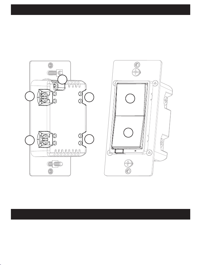
A. Ground (Green/Bare)
B. Line or Load (Black)
C. Line or Load (Black)
D. Traveler (Red/Other)
E. Neutral (White)
E. Top rocker — press & release to turn dimmer
ON, press & hold to increasbrightness
F. Bottom rocker — press & release to turn
dimmer OFF, press & hold to dim
WARNING — SHOCK HAZARD
Turn OFF the power to the branch circuit for the dimmer and lighting fixture at the service panel.
All wiring connections must be made with the POWER OFF to avoid personal injury and/or damage
to the dimmer. This device is intended for installation in accordance with the National Electric Code
and local regulations in the United States or the Canadian Electrical Code and local regulations in
Canada. If you are unsure or uncomfortable about performing this installation, consult a
qualified electrician.
A
BD
E
F
1
G
C
MULTI-SWITCH WIRING
Add-on switch model 12723/46199 is required for multi-switch
installations. For more information on multi-switch installa-
tions, refer to the add-on switch manual.
SINGLE-SWITCH WIRING
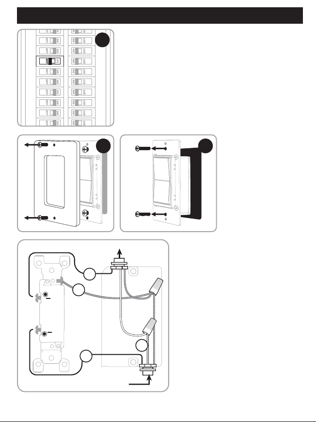
1. Shut o power to the circuit at circuit breaker
or fuse box.
IMPORTANT! Verify power is OFF to switch box
before continuing.
2. Remove wallplate.
3. Remove the switch mounting screws.
2 3
OUT TO
LIGHT (LOAD)
FROM
BREAKER BOX
B
A
C
E
4. Carefully remove the switch from the
switch box. DO NOT disconnect the wires.
5. There are up to five screw terminals on the
dimmer; these are marked:
A. GROUND — Green/Bare
B. LINE OR LOAD — Black (connected to
power or lighting)
C. LINE OR LOAD — Black (connected to
power or lighting)
D. TRAVELER — Red/Other (only in
3-way installations)
E. NEUTRAL — White
Match these screw terminals to the wires
connected to the existing switch.
6. Disconnect the wires from the existing switch. Label wires according to the previous
terminal connection.
OBSERVE IMPORTANT WIRING INFORMATION
IMPORTANT! This dimmer is rated for and intended to only be used with copper wire.
WIRE GAUGE REQUIREMENTS
Use 14AWG or larger wires suitable for at least 80° C for supplying line (hot), load, neutral, ground and traveler
connections.
WIRE STRIP LENGTH
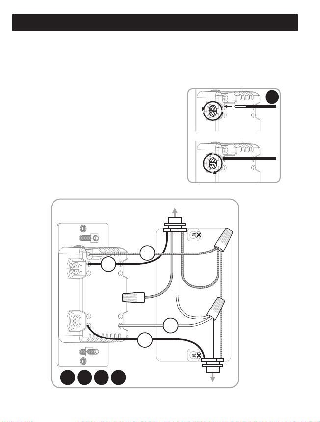
7.
For attachment using the enclosure’s holes, strip insulation
5/8in. (16mm). Do not wrap wires around screws. UL specifies
the tightening torque for the screws is 14Kgf-cm (12lbf-in).
8.
Connect the green or bare copper ground wire to the
GROUND terminal (A).
9. Connect the black wire from the light to either LINE/LOAD
terminal (B).
10. Connect the black wire from the electrical service panel (hot)
to the other LINE/LOAD terminal (C).
11. Connect the white wire to the neutral terminal (E) (use a
jumper wire if needed).
7
Insert wires into holes, do not wrap
wires around screws. OUT TO
LIGHT (LOAD)
FROM
BREAKER BOX
Do not remove screws.
A
B
C
E
8 9 10 11
12. Insert dimmer into the switch box being careful not to pinch or crush wires.
13. Mount the wallplate.
14. Reapply power to the circuit at fuse box or circuit breaker and test the system.
REMOVING AND RESETTING THE DEVICE
1. Follow the instructions for your Z-Wave certified controller to remove a device from the
Z-Wave network.
2. Once the controller is ready to remove your device, press and release the top or bottom of the
smart dimmer (rocker).
RETURNING DIMMER TO FACTORY DEFAULTS
Quickly press ON (top) button three times, then, immediately press the OFF (bottom) button three
times. The LED will flash ON/OFF five times when completed successfully.
NOTE: This should only be used in the event your network’s primary controller is missing or other-
wise inoperable.
NOTE: SmartStart enabled products can be added into a Z-Wave network by scanning the QR code
on the product with a controller providing SmartStart inclusion. No further action is required and
the SmartStart product will be added automatically within 10 minutes of being switched on in the
network vicinity.
MANUAL CONTROL
The front panel rocker dimmer allows the user to turn ON/OFF the connected fixture.
1. To turn the connected fixture ON, press and release the top of the rocker.
2. To turn the connected fixture OFF, press and release the bottom of the rocker.
ADJUST DIM LEVELS
1. To increase brightness, press and hold the top of the rocker.
2. To decrease brightness, press and hold the bottom of the rocker.
CYCLE LED LIGHT
The LED below the dimmer acts as a guide light or status indicator.
How to cycle through options: Press up three times and down once quickly.
1. LED is ON when the load is OFF (guide light in the dark) (default).
2. LED is ON when the load is ON (indicates the dimmer is ON).
3. LED is always OFF.
4. LED is always ON (illuminates dimmer in the dark).
CONNECTING TO A Z-WAVE NETWORK
1. Follow the instructions for your Z-Wave
certified controller to add a device to the
Z-Wave network.
2. Once the controller is ready to add your device,
press and release the top or bottom of the
smart dimmer (rocker).
If prompted by the controller to enter the S2
security code, refer to the QR code/security
number on the back of the box or the QR code
label on the product.
This device supports Association Command Class (3 Groups)
• Association Group 1 supports Lifeline, Multilevel Switch
Report, Central Scene notification
• Association Group 2 supports Basic Set and is controlled by
pressing the ON or OFF button with the local load
• Association Group 3 supports Basic Set and is controlled by
double pressing the ON or OFF button
• Each Association Group supports 5 total nodes
CHANGING THE COLOR OF THE PADDLE
NOTE: Additional colors available on
www.byjasco.com.
1. Lift the air gap tab at the base of the
paddle.
2. Push side tabs in on one side and
then the other to release paddle. Lift
the cover up and o.
3. Simply put the new paddle onto the
dimmer by inserting the air gap and
side tabs and snapping securely
into place.
Jasco Products Company warrants this product to be free from manufacturing defects for five years from the original
date of consumer purchase. This warranty is limited to the repair or replacement of this product only and does not extend
to consequential or incidental damage to other products that may be used with this product. This warranty is in lieu of
all other warranties, expressed or implied. Some states do not allow limitations on how long an implied warranty lasts or
permit the exclusion or limitation of incidental or consequential damage, so the above limitations may not apply to you.
This warranty gives you specific rights and you may also have other rights which vary from state to state. Please contact
our U.S.-based Consumer Care at 1-800-654-8483 (option 1) between 7AM – 8PM, M-F, Central Time or www.byjasco.com
if the unit should prove defective within the warranty period.
This product can be included and operated in any Z-Wave network with other Z-Wave certified devices from other manu-
facturers and/or other applications. All non-battery operated nodes within the network will act as repeaters regardless of
vendor to increase reliability of the network.
ZW3010
Power: 120VAC, 60Hz
Signal (frequency): 908.4/916MHz
Maximum loads: 1-gang 600W, 2-gang 500W or 3-gang 400W incandescent, 300W dimmable CFL/LED
Range: Up to 150ft. line of sight between the wireless controller and the closest Z-Wave receiver module
Operating temperature range: 32-104° F (0-40° C)
Type 1 enclosure, independently mounted (vertical position only), operating control: type 1.c action, pollution degree (2),
rated impulse voltage (2500V), software class A
For indoor use only
Specifications subject to change without notice due to continuing product improvement
WARNING
RISK OF FIRE
RISK OF ELECTRICAL SHOCK
RISK OF BURNS
CONTROLLING APPLIANCES
CAUTION: TO REDUCE THE RISK
OF OVERHEATING AND POSSIBLE
DAMAGE TO OTHER EQUIPMENT,
DO NOT INSTALL TO CONTROL A
RECEPTACLE, A MOTOR-OPERATED
APPLIANCE, FLUORESCENT LIGHTING
FIXTURE OR TRANSFORMER-SUPPLIED
APPLIANCE.
• ONLY USE TO CONTROL
INCANDESCENT OR DIMMABLE
CFL/LED BULBS
• DO NOT EXCEED RATINGS
• DO NOT USE TO CONTROL ANY
DEVICE WHERE UNINTENDED
OPERATION COULD CAUSE
UNSAFE CONDITIONS (HEAT
LAMP, SUN LAMP, ETC.)
• FOR INDOOR USE ONLY
This device complies with Part 15 of the FCC and Industry Canada license-exempt
RSS standards. Operation is subject to the following two conditions: (1) this device
may not cause harmful interference, and (2) this device must accept any interference
received, including interference that may cause undesired operation.
FCC NOTE: The manufacturer is not responsible for any radio or TV interference
caused by unauthorized modifications to this equipment. Such modifications could
void the user’s authority to operate the equipment
NOTE: This equipment has been tested and found to comply with the limits for a
Class B digital device, pursuant to Part 15 of the FCC Rules. These limits are designed
to provide reasonable protection against harmful interference in a residential instal-
lation. This equipment generates, uses and can radiate radio frequency energy, and
if not installed and used in accordance with the instructions, may cause harmful inter-
ference to radio communications. However, there is no guarantee interference will not
occur in a particular installation. If this equipment does cause harmful interference to
radio or television reception, which can be determined by turning the equipment o
and on, the user is encouraged to try to correct the interference by one or more of
the following measures:
• Reorient or relocate the receiving antenna.
• Increase the separation between the equipment and receiver.
• Connect the equipment into an outlet on a circuit dierent to which the receiver
is connected.
• Consult the dealer or an experienced radio/TV technician for help.
Important note: To comply with the FCC RF exposure compliance requirements, no
change to the antenna or the device is permitted. Any change to the antenna or the
device could result in the device exceeding the RF exposure requirements and void
user’s authority to operate the device.
Responsible Party - US Contact Information
FCC — U2ZZW3010 | IC: 6924A-ZW3010
Jasco Products Company | Model: ZW3010/46203
10 E. Memorial Rd., Oklahoma City, OK 73114 | 1-800-654-8483
CAN ICES-3(B)/NMB-3(B)
NOT FOR USE WITH MEDICAL
OR LIFE-SUPPORT EQUIPMENT
Z-Wave enabled devices should never
be used to supply power to or control
the ON/OFF status of medical and
life-support equipment.
12 13
Z-WAVE DSK
PIN: XXXXX
DSK :
XXXXX
-25651-22671
-26939-47599
-19612-25872
-47752
1.
2.
Control inalámbrico para iluminación
certificado por Z-Wave®
Todas las marcas que aparecen aquí son marcas
registradas de sus respectivos dueños
HECHO EN CHINA
Distribuido por Jasco Products Company LLC,
10 E Memorial Rd., Oklahoma City, Oklahoma 73114.
©JASCO 2021 | ZW3010 | 46203 | 01/14/21 v4
Interruptor
de pared
reductor
de luz
inteligente
46203
ZW3010
Para acceder a ofertas, registrar su compra y
darnos su opinión sobre nosotros, tan solo
escanee el código o visite byjasco.com/deals
¡Gracias por su compra!
¿Le gusta nuestro
producto?
Deje una reseña en
amazon.com
Para ver más Enbrighten
productos visite nuestro sitio web
www.ezzwave.com
¿Tiene algún
problema?
Díganos cómo
podemos ayudar. Llame
al 1-800-654-8483, entre
las, 7 a.m. y las 8 p.m.,
hora estándar del centro
Ofertas exclusivas
1. CARACTERÍSTICAS
2. INSTALACIÓN
• Se puede utilizar en una instalación unipolar o hasta con cuatro interruptores auxiliares (modelo
12723/46199) en configuraciones de cableado de 3 o 4vías
• Compatible con todas las bombillas incandescentes y la mayoría de las bombillas CFL/LED
• Detección de línea/carga automática
• Un LED azul indica la ubicación del interruptor en habitaciones oscuras
• nstalación de terminales de tornillo — requiere de conexiones de cables para line (hot) (línea
[con corriente]), load (carga), neutral (neutro) y ground (tierra). Se requiere un cable puente para
instalaciones de 3 o 4 vías.
• Este dispositivo Z-Wave cuenta con características avanzadas que le permiten personalizar
su experiencia. Consulte la lista integral de configuraciones ajustables en www.ezzwave.com
A. Tierra (verde/pelado)
B. Línea o carga (negro)
C. Línea o carga (negro)
D. Puente (rojo/otro)
E. Neutro (blanco)
F. Interruptor basculante superior: presione y suelte
para encender el atenuador de luz y presione sin
soltar para aumentar la intensidad de brillo.
G. Interruptor basculante inferior: presione y suelte para
apagar el atenuador de luz y presione sin soltar
para atenuar.
ADVERTENCIA— DESCARGA ELÉCTRICA
TInterrumpa la alimentación al circuito derivado del interruptor y al accesorio de iluminación desde el
panel de servicio. Todas las conexiones de cableados deben realizarse con el SUMINISTRO DE CORRIENTE
INTERRUMPIDO para evitar lesiones personales o daños al interruptor. Este dispositivo está diseñado para
la instalación conforme al Código de Normas de Electricidad y las reglamentaciones locales en EE.UU. o el
Código de Normas de Electricidad y las reglamentaciones locales en Canadá. Si no está seguro o tiene dudas
sobre cómo realizar la instalación, contacte a un electricista profesional.
A
BD
E
F
G
C
2. INSTALACIÓN (CONT.)
1CABLEADO DEL INTERRUPTOR MULTIFÁSICO
El interruptor auxiliar UltraPro modelo 12723/46199 es necesario
para instalaciones múltiples vías. Para obtener más información
sobre instalaciones múltiples vías, consulte el manual o la guía
rápida que viene con el interruptor auxiliar.
CABLEADO DEL INTERRUPTOR MONOFÁSICO
1. Interrumpa la alimentación al circuito desde el panel de fusibles o
el de cortacircuitos..
¡IMPORTANTE! Antes de continuar, compruebe que se haya
INTERRUMPIDO la alimentación eléctrica a la caja del interruptor.
2. Retire la placa.
3. Retire los tornillos de soporte del interruptor.
2 3
OUT TO
LIGHT (LOAD)
FROM
BREAKER BOX
B
A
C
E
4. Saque el interruptor de la caja con cuidado.
NO desconecte los cables.
5. Hay hasta cinco terminales de tornillo en el
atenuador; están marcados de la
siguiente manera:
A. GROUND (Tierra): verde/pelado.
B. LINEA O CARGA (LINE OR LOAD) —
Negro (conectado a la alimentación o
a la luz).
C. LINEA O CARGA (LINE OR LOAD) —
Negro (conectado a la alimentación o
a la luz).
D. TRAVELER (Puente): rojo/otro (solo en
instalaciones de 3vías).
E. NEUTRAL (Neutro— blanco).
Z-Wave® certified
wireless lighting control
All brand names shown are trademarks of
their respective owners
MADE IN CHINA/HECHO EN CHINA
Distributed by Jasco Products Company LLC,
10 E. Memorial Rd., Oklahoma City, OK 73114.
©JASCO 2021 | ZW3010 | 46203 | 01/14/21 v4
In-Wall
Smart
Dimmer
46203
ZW3010
For deals, to register
your purchase and to
tell us how we’re
doing, simply scan
the code or visit
byjasco.com/deals
Instructions made easy
Read instructions or
watch easy-to-follow
video. Scan code or visit
byjasco.com/46203i
Thank you for your purchase!
Like our product?
Leave a review
on amazon.com
Having problems?
Let us know how
we can help.
1-800-654-8483
between 7AM-8PM,
M-F, Central Time.
For additional Enbrighten
products, visit our website.
www.ezzwave.com
1. FEATURES 2. INSTALLATION (CONT.)
2. INSTALLATION (CONT.) 2. INSTALLATION (CONT.) 3. CONNECTION (CONT.)
OPTIONAL CUSTOMIZATION
3. CONNECTION
WARRANTY
FCC/IC
SPECIFICATIONS -IMPORTANT!
Z-WAVE INTEROPERABILITY
2. INSTALLATION
• May be used in single-pole installation or with up to four add-on switches (model
12723/46199) in 3-way or 4-way wiring configurations
• Compatible with all incandescent and most dimmable CFL/LED bulbs
• Auto line/load detection
• Blue LED indicates dimmer location in a dark room
• Screw terminal installation — requires wiring connections for line (hot), load, neutral and
ground. Traveler wire required for 3-way or 4-way installation
• This Z-Wave device has advanced features that allow you to customize your experience. For
a complete list of adjustable configurations, visit www.ezzwave.com
A. Ground (Green/Bare)
B. Line or Load (Black)
C. Line or Load (Black)
D. Traveler (Red/Other)
E. Neutral (White)
E. Top rocker — press & release to turn dimmer
ON, press & hold to increasbrightness
F. Bottom rocker — press & release to turn
dimmer OFF, press & hold to dim
WARNING — SHOCK HAZARD
Turn OFF the power to the branch circuit for the dimmer and lighting fixture at the service panel.
All wiring connections must be made with the POWER OFF to avoid personal injury and/or damage
to the dimmer. This device is intended for installation in accordance with the National Electric Code
and local regulations in the United States or the Canadian Electrical Code and local regulations in
Canada. If you are unsure or uncomfortable about performing this installation, consult a
qualified electrician.
A
BD
E
F
1
G
C
MULTI-SWITCH WIRING
Add-on switch model 12723/46199 is required for multi-switch
installations. For more information on multi-switch installa-
tions, refer to the add-on switch manual.
SINGLE-SWITCH WIRING
1. Shut o power to the circuit at circuit breaker
or fuse box.
IMPORTANT! Verify power is OFF to switch box
before continuing.
2. Remove wallplate.
3. Remove the switch mounting screws.
2 3
OUT TO
LIGHT (LOAD)
FROM
BREAKER BOX
B
A
C
E
4. Carefully remove the switch from the
switch box. DO NOT disconnect the wires.
5. There are up to five screw terminals on the
dimmer; these are marked:
A. GROUND — Green/Bare
B. LINE OR LOAD — Black (connected to
power or lighting)
C. LINE OR LOAD — Black (connected to
power or lighting)
D. TRAVELER — Red/Other (only in
3-way installations)
E. NEUTRAL — White
Match these screw terminals to the wires
connected to the existing switch.
6. Disconnect the wires from the existing switch. Label wires according to the previous
terminal connection.
OBSERVE IMPORTANT WIRING INFORMATION
IMPORTANT! This dimmer is rated for and intended to only be used with copper wire.
WIRE GAUGE REQUIREMENTS
Use 14AWG or larger wires suitable for at least 80° C for supplying line (hot), load, neutral, ground and traveler
connections.
WIRE STRIP LENGTH
7.
For attachment using the enclosure’s holes, strip insulation
5/8in. (16mm). Do not wrap wires around screws. UL specifies
the tightening torque for the screws is 14Kgf-cm (12lbf-in).
8.
Connect the green or bare copper ground wire to the
GROUND terminal (A).
9. Connect the black wire from the light to either LINE/LOAD
terminal (B).
10. Connect the black wire from the electrical service panel (hot)
to the other LINE/LOAD terminal (C).
11. Connect the white wire to the neutral terminal (E) (use a
jumper wire if needed).
7
Insert wires into holes, do not wrap
wires around screws. OUT TO
LIGHT (LOAD)
FROM
BREAKER BOX
Do not remove screws.
A
B
C
E
8 9 10 11
12. Insert dimmer into the switch box being careful not to pinch or crush wires.
13. Mount the wallplate.
14. Reapply power to the circuit at fuse box or circuit breaker and test the system.
REMOVING AND RESETTING THE DEVICE
1. Follow the instructions for your Z-Wave certified controller to remove a device from the
Z-Wave network.
2. Once the controller is ready to remove your device, press and release the top or bottom of the
smart dimmer (rocker).
RETURNING DIMMER TO FACTORY DEFAULTS
Quickly press ON (top) button three times, then, immediately press the OFF (bottom) button three
times. The LED will flash ON/OFF five times when completed successfully.
NOTE: This should only be used in the event your network’s primary controller is missing or other-
wise inoperable.
NOTE: SmartStart enabled products can be added into a Z-Wave network by scanning the QR code
on the product with a controller providing SmartStart inclusion. No further action is required and
the SmartStart product will be added automatically within 10 minutes of being switched on in the
network vicinity.
MANUAL CONTROL
The front panel rocker dimmer allows the user to turn ON/OFF the connected fixture.
1. To turn the connected fixture ON, press and release the top of the rocker.
2. To turn the connected fixture OFF, press and release the bottom of the rocker.
ADJUST DIM LEVELS
1. To increase brightness, press and hold the top of the rocker.
2. To decrease brightness, press and hold the bottom of the rocker.
CYCLE LED LIGHT
The LED below the dimmer acts as a guide light or status indicator.
How to cycle through options: Press up three times and down once quickly.
1. LED is ON when the load is OFF (guide light in the dark) (default).
2. LED is ON when the load is ON (indicates the dimmer is ON).
3. LED is always OFF.
4. LED is always ON (illuminates dimmer in the dark).
CONNECTING TO A Z-WAVE NETWORK
1. Follow the instructions for your Z-Wave
certified controller to add a device to the
Z-Wave network.
2. Once the controller is ready to add your device,
press and release the top or bottom of the
smart dimmer (rocker).
If prompted by the controller to enter the S2
security code, refer to the QR code/security
number on the back of the box or the QR code
label on the product.
This device supports Association Command Class (3 Groups)
• Association Group 1 supports Lifeline, Multilevel Switch
Report, Central Scene notification
• Association Group 2 supports Basic Set and is controlled by
pressing the ON or OFF button with the local load
• Association Group 3 supports Basic Set and is controlled by
double pressing the ON or OFF button
• Each Association Group supports 5 total nodes
CHANGING THE COLOR OF THE PADDLE
NOTE: Additional colors available on
www.byjasco.com.
1. Lift the air gap tab at the base of the
paddle.
2. Push side tabs in on one side and
then the other to release paddle. Lift
the cover up and o.
3. Simply put the new paddle onto the
dimmer by inserting the air gap and
side tabs and snapping securely
into place.
Jasco Products Company warrants this product to be free from manufacturing defects for five years from the original
date of consumer purchase. This warranty is limited to the repair or replacement of this product only and does not extend
to consequential or incidental damage to other products that may be used with this product. This warranty is in lieu of
all other warranties, expressed or implied. Some states do not allow limitations on how long an implied warranty lasts or
permit the exclusion or limitation of incidental or consequential damage, so the above limitations may not apply to you.
This warranty gives you specific rights and you may also have other rights which vary from state to state. Please contact
our U.S.-based Consumer Care at 1-800-654-8483 (option 1) between 7AM – 8PM, M-F, Central Time or www.byjasco.com
if the unit should prove defective within the warranty period.
This product can be included and operated in any Z-Wave network with other Z-Wave certified devices from other manu-
facturers and/or other applications. All non-battery operated nodes within the network will act as repeaters regardless of
vendor to increase reliability of the network.
ZW3010
Power: 120VAC, 60Hz
Signal (frequency): 908.4/916MHz
Maximum loads: 1-gang 600W, 2-gang 500W or 3-gang 400W incandescent, 300W dimmable CFL/LED
Range: Up to 150ft. line of sight between the wireless controller and the closest Z-Wave receiver module
Operating temperature range: 32-104° F (0-40° C)
Type 1 enclosure, independently mounted (vertical position only), operating control: type 1.c action, pollution degree (2),
rated impulse voltage (2500V), software class A
For indoor use only
Specifications subject to change without notice due to continuing product improvement
WARNING
RISK OF FIRE
RISK OF ELECTRICAL SHOCK
RISK OF BURNS
CONTROLLING APPLIANCES
CAUTION: TO REDUCE THE RISK
OF OVERHEATING AND POSSIBLE
DAMAGE TO OTHER EQUIPMENT,
DO NOT INSTALL TO CONTROL A
RECEPTACLE, A MOTOR-OPERATED
APPLIANCE, FLUORESCENT LIGHTING
FIXTURE OR TRANSFORMER-SUPPLIED
APPLIANCE.
• ONLY USE TO CONTROL
INCANDESCENT OR DIMMABLE
CFL/LED BULBS
• DO NOT EXCEED RATINGS
• DO NOT USE TO CONTROL ANY
DEVICE WHERE UNINTENDED
OPERATION COULD CAUSE
UNSAFE CONDITIONS (HEAT
LAMP, SUN LAMP, ETC.)
• FOR INDOOR USE ONLY
This device complies with Part 15 of the FCC and Industry Canada license-exempt
RSS standards. Operation is subject to the following two conditions: (1) this device
may not cause harmful interference, and (2) this device must accept any interference
received, including interference that may cause undesired operation.
FCC NOTE: The manufacturer is not responsible for any radio or TV interference
caused by unauthorized modifications to this equipment. Such modifications could
void the user’s authority to operate the equipment
NOTE: This equipment has been tested and found to comply with the limits for a
Class B digital device, pursuant to Part 15 of the FCC Rules. These limits are designed
to provide reasonable protection against harmful interference in a residential instal-
lation. This equipment generates, uses and can radiate radio frequency energy, and
if not installed and used in accordance with the instructions, may cause harmful inter-
ference to radio communications. However, there is no guarantee interference will not
occur in a particular installation. If this equipment does cause harmful interference to
radio or television reception, which can be determined by turning the equipment o
and on, the user is encouraged to try to correct the interference by one or more of
the following measures:
• Reorient or relocate the receiving antenna.
• Increase the separation between the equipment and receiver.
• Connect the equipment into an outlet on a circuit dierent to which the receiver
is connected.
• Consult the dealer or an experienced radio/TV technician for help.
Important note: To comply with the FCC RF exposure compliance requirements, no
change to the antenna or the device is permitted. Any change to the antenna or the
device could result in the device exceeding the RF exposure requirements and void
user’s authority to operate the device.
Responsible Party - US Contact Information
FCC — U2ZZW3010 | IC: 6924A-ZW3010
Jasco Products Company | Model: ZW3010/46203
10 E. Memorial Rd., Oklahoma City, OK 73114 | 1-800-654-8483
CAN ICES-3(B)/NMB-3(B)
NOT FOR USE WITH MEDICAL
OR LIFE-SUPPORT EQUIPMENT
Z-Wave enabled devices should never
be used to supply power to or control
the ON/OFF status of medical and
life-support equipment.
12 13
Z-WAVE DSK
PIN: XXXXX
DSK :
XXXXX
-25651-22671
-26939-47599
-19612-25872
-47752
1.
2.
Control inalámbrico para iluminación
certificado por Z-Wave®
Todas las marcas que aparecen aquí son marcas
registradas de sus respectivos dueños
HECHO EN CHINA
Distribuido por Jasco Products Company LLC,
10 E Memorial Rd., Oklahoma City, Oklahoma 73114.
©JASCO 2021 | ZW3010 | 46203 | 01/14/21 v4
Interruptor
de pared
reductor
de luz
inteligente
46203
ZW3010
Para acceder a ofertas, registrar su compra y
darnos su opinión sobre nosotros, tan solo
escanee el código o visite byjasco.com/deals
¡Gracias por su compra!
¿Le gusta nuestro
producto?
Deje una reseña en
amazon.com
Para ver más Enbrighten
productos visite nuestro sitio web
www.ezzwave.com
¿Tiene algún
problema?
Díganos cómo
podemos ayudar. Llame
al 1-800-654-8483, entre
las, 7 a.m. y las 8 p.m.,
hora estándar del centro
Ofertas exclusivas
1. CARACTERÍSTICAS
2. INSTALACIÓN
• Se puede utilizar en una instalación unipolar o hasta con cuatro interruptores auxiliares (modelo
12723/46199) en configuraciones de cableado de 3 o 4vías
• Compatible con todas las bombillas incandescentes y la mayoría de las bombillas CFL/LED
• Detección de línea/carga automática
• Un LED azul indica la ubicación del interruptor en habitaciones oscuras
• nstalación de terminales de tornillo — requiere de conexiones de cables para line (hot) (línea
[con corriente]), load (carga), neutral (neutro) y ground (tierra). Se requiere un cable puente para
instalaciones de 3 o 4 vías.
• Este dispositivo Z-Wave cuenta con características avanzadas que le permiten personalizar
su experiencia. Consulte la lista integral de configuraciones ajustables en www.ezzwave.com
A. Tierra (verde/pelado)
B. Línea o carga (negro)
C. Línea o carga (negro)
D. Puente (rojo/otro)
E. Neutro (blanco)
F. Interruptor basculante superior: presione y suelte
para encender el atenuador de luz y presione sin
soltar para aumentar la intensidad de brillo.
G. Interruptor basculante inferior: presione y suelte para
apagar el atenuador de luz y presione sin soltar
para atenuar.
ADVERTENCIA— DESCARGA ELÉCTRICA
TInterrumpa la alimentación al circuito derivado del interruptor y al accesorio de iluminación desde el
panel de servicio. Todas las conexiones de cableados deben realizarse con el SUMINISTRO DE CORRIENTE
INTERRUMPIDO para evitar lesiones personales o daños al interruptor. Este dispositivo está diseñado para
la instalación conforme al Código de Normas de Electricidad y las reglamentaciones locales en EE.UU. o el
Código de Normas de Electricidad y las reglamentaciones locales en Canadá. Si no está seguro o tiene dudas
sobre cómo realizar la instalación, contacte a un electricista profesional.
A
BD
E
F
G
C
2. INSTALACIÓN (CONT.)
1CABLEADO DEL INTERRUPTOR MULTIFÁSICO
El interruptor auxiliar UltraPro modelo 12723/46199 es necesario
para instalaciones múltiples vías. Para obtener más información
sobre instalaciones múltiples vías, consulte el manual o la guía
rápida que viene con el interruptor auxiliar.
CABLEADO DEL INTERRUPTOR MONOFÁSICO
1. Interrumpa la alimentación al circuito desde el panel de fusibles o
el de cortacircuitos..
¡IMPORTANTE! Antes de continuar, compruebe que se haya
INTERRUMPIDO la alimentación eléctrica a la caja del interruptor.
2. Retire la placa.
3. Retire los tornillos de soporte del interruptor.
2 3
OUT TO
LIGHT (LOAD)
FROM
BREAKER BOX
B
A
C
E
4. Saque el interruptor de la caja con cuidado.
NO desconecte los cables.
5. Hay hasta cinco terminales de tornillo en el
atenuador; están marcados de la
siguiente manera:
A. GROUND (Tierra): verde/pelado.
B. LINEA O CARGA (LINE OR LOAD) —
Negro (conectado a la alimentación o
a la luz).
C. LINEA O CARGA (LINE OR LOAD) —
Negro (conectado a la alimentación o
a la luz).
D. TRAVELER (Puente): rojo/otro (solo en
instalaciones de 3vías).
E. NEUTRAL (Neutro— blanco).
Table of contents
Popular Dimmer manuals by other brands


Sunricher
Sunricher SR-2303DIN quick start guide

Stairville
Stairville D1210 owner's manual

elsner elektronik
elsner elektronik RF-L-DST 1-10 V manual

Lutron Electronics
Lutron Electronics Maestro Wireless MRF2-600M Quick start quide

Leviton
Leviton decora smart DZ1KD Installation instructions and operators manual

RC4 Wireless
RC4 Wireless DMX6dim-500 quick start guide

Lucci CONNECT
Lucci CONNECT 299043 installation instructions

LEGRAND
LEGRAND HPM 700TM instruction manual

City Theatrical
City Theatrical SHoW DMX Neo D4 user manual

ETC
ETC SmartModule 2 Connection and setup guide

MAGNITUDE LIGHTING
MAGNITUDE LIGHTING E Series installation guide

Leviton
Leviton Decora Mural MDI06-1 installation instructions