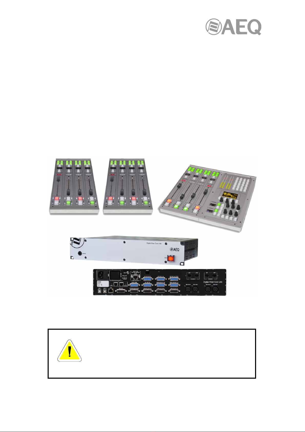
AEQ FORUM LITE User manual

AEQ
FORUM
LITE
ULTRA-COMPACT DIGITAL AUDIO MIXER
FOR BROADCAST APPLICATIONS
USER’S MANUAL
ED. 06/21
V. 1.5 - 10/05/2022
Software version 4.32, March 2022

AEQ FORUM LITE
Ultra-compact digital audio mixer
2
CONTENTS
1. INTRODUCTION....................................................................................................................... 5
1.1. General description............................................................................................................ 5
1.2. Specifications. .................................................................................................................... 7
1.2.1. General morphology. .............................................................................................. 7
1.2.2. Functionality. ........................................................................................................... 7
1.2.3. General features. .................................................................................................... 7
1.2.4. Standard Inputs and Outputs. ................................................................................. 7
1.2.5. Optional Inputs and Outputs. .................................................................................. 8
1.2.6. System processing capacity. .................................................................................. 8
2. PHYSICAL DESCRIPTION OF THE UNIT............................................................................... 9
2.1. Description of the control surface. ..................................................................................... 9
2.1.1. Channels. ................................................................................................................ 9
2.1.1.1. Routing keys. .......................................................................................... 11
2.1.1.2. SELECT. ................................................................................................. 11
2.1.1.3. Channel display....................................................................................... 11
2.1.1.4. CUE......................................................................................................... 11
2.1.1.5. Active processes indicator. ..................................................................... 12
2.1.1.6. ON AIR LED............................................................................................ 12
2.1.1.7. Fader. ...................................................................................................... 13
2.1.1.8. Channel activation keys. ......................................................................... 13
2.1.2. Control and monitoring section. ............................................................................ 14
2.1.2.1. Control VU meters................................................................................... 15
2.1.2.2. Programmable keys. ............................................................................... 16
2.1.2.3. Main display. ........................................................................................... 17
2.1.2.4. Control room monitoring section. ............................................................ 17
2.1.2.5. Studio room monitoring and Talkback sections. ..................................... 18
2.2. Audio engine description.................................................................................................. 21
2.2.1. Power supply......................................................................................................... 22
2.2.2. Auxiliary connections. ........................................................................................... 23
2.2.2.1. GPIO. ...................................................................................................... 23
2.2.2.1.1. Opto-coupled GPI. .................................................................. 23
2.2.2.1.2. Opto-coupled GPO. ................................................................ 24
2.2.2.1.3. Physical contact GPO. ............................................................ 25
2.2.2.2. Ethernet Port. .......................................................................................... 26
2.2.2.3. Control and studio monitors. ................................................................... 26
2.2.2.4. CUE......................................................................................................... 27
2.2.2.5. Control headphones................................................................................ 27
2.2.2.6. Studio headphones. ................................................................................ 27
2.2.3. Generic audio inputs and outputs. ........................................................................ 28
2.2.3.1. Accessing the programming jumpers...................................................... 28
2.2.3.2. Digital inputs............................................................................................ 30
2.2.3.3. Digital outputs. ........................................................................................ 31
2.2.3.4. Analog inputs. ......................................................................................... 33
2.2.3.5. Analog outputs. ....................................................................................... 33
2.2.3.6. MIC/LINE inputs. ..................................................................................... 34
2.2.3.7. USB inputs and outputs. ......................................................................... 36
2.2.3.8. AoIP inputs and outputs. ......................................................................... 37
2.2.4. Optional inputs/outputs modules........................................................................... 37
2.2.4.1. MADI multichannel optional module. ...................................................... 37
2.2.4.2. Telephone hybrid optional module.......................................................... 38
2.2.5. Wiring. ................................................................................................................... 38
3. DESCRIPTION OF THE INTERNAL MENU........................................................................... 40
3.1. "CLOCK" menu. ............................................................................................................... 40
3.2. "LOGIN/LOGOUT" menu. ................................................................................................ 42
3.3. "MEMORY" menu. ........................................................................................................... 44

AEQ FORUM LITE
Ultra-compact digital audio mixer
3
3.4. "MAIN MENU". ................................................................................................................. 44
3.4.1. "INFO" menu. ........................................................................................................ 45
3.4.2. "SETUP" menu...................................................................................................... 46
3.4.3. "SELECT" menu.................................................................................................... 47
3.4.3.1. "INPUT" menu......................................................................................... 47
3.4.3.1.1. Dynamics menu: Compressor/Limiter and Noise Gate. ......... 48
3.4.3.1.2. Equalizer and filter menu. ....................................................... 51
3.4.3.1.3. Expanded information menu. .................................................. 52
3.4.3.1.3.1. "CFG" menu......................................................... 53
3.4.3.1.3.2. "FADER" menu. ................................................... 53
3.4.3.1.3.3. "ROUTE" menu.................................................... 54
3.4.3.2. "OUTPUT" menu..................................................................................... 55
4. CONFIGURATION SOFTWARE. ........................................................................................... 57
4.1. "Administration" menu...................................................................................................... 60
4.1.1. "Configurations" submenu. ................................................................................... 60
4.1.2. "User Configuration" submenu.............................................................................. 64
4.1.3. "About Forum Lite Setup" submenu...................................................................... 66
4.2. "Hardware Configuration" menu. ..................................................................................... 66
4.2.1. "Board Configuration" submenu............................................................................ 67
4.2.1.1. "Internal Module/Virtual - Configuration" section. ................................... 68
4.2.2. "Mixer Bus Configuration" submenu. .................................................................... 73
4.2.2.1. Configuration of MPX buses menu. "Clean Feed" mode........................ 75
4.2.3. "I/O Configuration" submenu. ............................................................................... 80
4.2.3.1. Advanced configuration of input channels menu. ................................... 81
4.2.3.2. Advanced configuration of output channels menu.................................. 85
4.2.4. "Monitoring Configuration" submenu. ................................................................... 86
4.2.4.1. "Studio Room Section"............................................................................ 87
4.2.4.2. "Control Room Section". ......................................................................... 87
4.2.5. "Visual Radio" submenu. ...................................................................................... 88
4.2.6. "NTP Client Configuration" submenu.................................................................... 90
4.2.7. "Vumeters" submenu. ........................................................................................... 91
4.2.8. "Options" submenu. .............................................................................................. 92
4.3. "Programmable Configuration" menu. ............................................................................. 93
4.3.1. "Routing Configuration" submenu......................................................................... 93
4.3.2. "Programmable Keys" submenu. .......................................................................... 95
4.3.2.1. Basic configuration of programmable keys. ............................................ 95
4.3.2.2. Configuration of "General" programmable keys...................................... 96
4.3.2.3. Configuration of "Salvo" programmable keys. ........................................ 98
4.3.2.4. Configuration of "Codec" programmable keys...................................... 100
4.3.2.5. Configuration of "Multiplex" programmable keys. ................................. 104
4.3.2.6. Configuration of "Cue Reset" programmable key. ................................ 104
4.3.2.7. Configuration of "Orders" programmable keys. .................................... 105
4.3.2.8. Configuration of "Memory" programmable keys. .................................. 105
4.3.2.9. Configuration of "Studio Monitor Attenuation" programmable keys...... 106
4.3.2.10. Configuration of "Auto Cue" programmable key. ................................ 107
4.3.2.11. Configuration of "A/B Mode" programmable key. ............................... 107
4.3.3. "Mic Group Configuration" submenu................................................................... 108
4.3.4. "Preset Configuration" submenu......................................................................... 110
4.3.4.1. Advanced configuration of Compressor/Limiter.................................... 112
4.3.4.2. Advanced configuration of Noise Gate. ................................................ 113
4.3.4.3. Advanced configuration of Equalizer. ................................................... 114
4.3.4.4. Advanced configuration of Low Pass Filter........................................... 115
4.3.4.5. Advanced configuration of High Pass Filter. ......................................... 115
4.3.5. "SnapShot Configuration" submenu. .................................................................. 116
4.3.5.1. Advanced configuration of inputs.......................................................... 121
4.3.5.2. Advanced configuration of outputs........................................................ 123
4.4. "Firmware Upgrade" menu............................................................................................. 124
4.4.1. "Tree View" submenu. ........................................................................................ 124
4.4.2. "Upgrade View" submenu. .................................................................................. 127

AEQ FORUM LITE
Ultra-compact digital audio mixer
4
4.4.3. "Log View" submenu. .......................................................................................... 128
5. A.E.Q. GUARANTEE............................................................................................................ 129
APPENDIX A. SIGNALLING CONNECTION........................................................................... 130
APPENDIX B. ADDITIONAL INFORMATION.......................................................................... 135

AEQ FORUM LITE
Ultra-compact digital audio mixer
5
1. INTRODUCTION.
1.1. General description.
AEQ FORUM LITE is an ultra-compact digital audio mixer for Radio and Television consisting in
a control surface and audio engine, specially designed for ON AIR broadcast control, and very
adaptable to different work situations. It comprises all the basic necessary functions for this kind
of environments: automatic monitor cut, cough cut, fader start, signaling control, signals for
external equipment automation, external communications management, intercom, etc.
Its reduced size makes this mixer perfectly adaptable to many different scenarios: self-control,
control-studio, audio control in television, sound production, mixed configurations, integration in
large systems, etc.
One of the main qualities of AEQ FORUM LITE is the extensive internal routing capacity which
provides: 28 inputs and 30 outputs for analogue, digital or microphone audio signals, 16 or 32
inputs/outputs multichannel audio over an AoIP (audio over IP) link, 2 optional inputs/outputs for
telephone hybrid and another 64 optional inputs/outputs multichannel audio over a MADI link
(and exclusive regarding AoIP functionality: both options can’t be active at the same time).
NOTE: The exterior of equipment and some screens may vary depending on version.
Control power and simplicity of use has been combined into AEQ FORUM LITE to meet from
the most basic to advanced operation needs, from an 8 faders control surface.
WARNING
The cable that connects control and monitoring module and audio
engine carries power supply. The same happens with the cable that
connects control and monitoring module to the first 4 faders module
and with the cables that connect the following 4 faders modules.
In order to avoid any damage to the unit is VERY IMPORTANT to
turn off the unit before connecting or disconnecting these cables.

AEQ FORUM LITE
Ultra-compact digital audio mixer
6
All basic functions of activation, level adjustment and routing have their specific controls on
each channel of the FORUM LITE surface, while less common adjustments are included in a
set of contextual controls common to all channels and accessible with just one or two
keystrokes: simplicity and clarity of use for dynamic control without handling error.
The flexibility offered through the configuration of AEQ FORUM LITE enables the free
assignment of any audio input of the system to any control channel, and changing the
distribution of signals from the surface itself or the associated configuration software.
The FORUM LITE digital mixer includes memory banks that store the settings for each signal:
control surface signal distribution, routing to the output buses, management of parameters and
activation of the different available audio processes. This allows the console to adapt easily to
different programs with different technical requirements.
Its Ethernet port enables the local or remote interconnectivity, facilitating set-up and
maintenance, monitoring and control.
FORUM LITE has also been designed to ensure interoperability with communications
equipment and future developments by AEQ or other manufacturers.
4 faders module 4 faders module
The data and power supply output from console to control surface is located at the right of the
power supply input of the "core". It is designed for use with straight Ethernet cabling, but also
carries proprietary power supply lines. Please use the cable provided with the unit only. If
necessary, this connection could be made by means of a cable of up to 250 meters, using a
continuous CAT5E shielded (FTP) cable (or better) and checking that the shield is connected
to the connectors case.
The example shows the connection diagram of AEQ FORUM LITE console. The data and
power supply output from "core" must be always connected to the left RJ45 connector of
control and monitoring module (rear view). The first 4 faders module is also connected by
means of the same type of cable from the right RJ45 connector of control and monitoring
module to the left RJ45 connector of 4 faders module (rear view). The following 4 faders
modules will be connected from the right RJ45 connector of a 4 faders module to the left RJ45
connector of the following 4 faders module (rear view).
Control and
monitoring module 4 faders module
"Core" or "Engine"

AEQ FORUM LITE
Ultra-compact digital audio mixer
7
1.2. Specifications.
1.2.1. General morphology.
•Ultra-compact design split in control surface and associated audio core.
•Control surface with 4 physical faders (100mm) modules.
•Core: 2U 19" chassis including audio inputs and outputs, processing, power supply and
internal equipment control hardware. Optional modules for redundant power supply,
double telephone hybrid and multi-channel MADI, all of them easy to install and
maintain.
1.2.2. Functionality.
•Cough mute, studio and control room ON-AIR signalling, faderstart, remote PFL, talk-
back, automatic speaker mute.
•N-1 output configuration.
•Control of integrated external equipment (AEQ hybrids and codecs) and internal hybrids
via programmable key section.
•Optional pre-fader / post-fader routing depending on the used buses.
•Control communication via 10/100 Ethernet connection using TCP/IP protocol.
•Boot-up using last used settings.
•System input signals can be assigned to any control channel.
•System settings are stored in the on-board memory: up to 7 available memory
positions.
1.2.3. General features.
•All system signals configurable for monitoring in Control, Studio, CUE Headphones and
VU-meters.
•4 direct routing buttons on each channel.
•Silent operation by convection cooling. AEQ FORUM LITE is ideally suited for self-
operated applications.
•Talk-back function assigned to microphone 4, with 4 PTT buttons for direct intercom.
•2 built-in headphone outputs. In addition, a stereo line output can be assigned for
secondary headphones.
•2 precision stereo VU meters.
•Test tone (1KHz) generator.
•Externally synchronized clock, timer and stopwatch.
•Electronically balanced microphone inputs with selectable micro or line level and
Phantom power.
•Electronically balanced analog line inputs and outputs.
•Transformer balanced digital inputs and outputs.
•Sampling rate converters for the digital inputs.
•Redundant power supply (optional).
•The data and power supply connection from core to control surface is made by means
of a supplied straight Ethernet cable that carries proprietary power supply. If
necessary, this connection could be made by means of a cable of up to 250 meters,
using a continuous CAT5E shielded (FTP) cable (or better) and checking that the
shield is connected to the connectors case.
1.2.4. Standard Inputs and Outputs.
•4 mic/line mono inputs.
•2 USB digital stereo inputs/outputs.
•4 AES/EBU digital stereo inputs/outputs that can be configured as SPDIF.
•12 analog mono inputs / 8 analog mono outputs (that can be configured as individual
stereo pairs).
•Bi-directional AoIP (audio over IP) interface handling up to 32 mono inputs and outputs.

AEQ FORUM LITE
Ultra-compact digital audio mixer
8
•Analog stereo outputs for Control, Studio, CUE and Studio primary Headphone
monitoring.
•Analog stereo amplified output for Control Headphones, jack ¼".
•8 opto-coupled GPI’s, 8 opto-coupled GPO’s and 4 GPO’s with relays.
1.2.5. Optional Inputs and Outputs.
•Dual line Digital Telephone Hybrid with two RJ-11 Line connectors and two RJ-11
connectors for Telephone SET.
•Bi-directional MADI fiber-optic interface handling up to 64 digital inputs and outputs.
IMPORTANT NOTE: MADI functionality is not compatible with AoIP (audio over IP)
functionality, both options can’t be active at the same time.
1.2.6. System processing capacity.
•48 kHz, 24 bit internal sampling frequency.
•±12dB gain control (analog and digital line inputs and outputs signals - including signals
not visible on control surface).
•Gain control for microphone inputs: from -36 to +19dB.
•Selectable balance/panoramic control on all channels.
•Selective phase reverse.
•Audio processing for 16 stereo signals (up to 8 on fader plus 8 signals not visible on
control surface).
•Pre-defined audio processing that allows manual adjustment.
•Available audio effects: 3 bands equalizer with adjustable Q value, high pass and low
pass filters, compressor/limiter and noise gate.

AEQ FORUM LITE
Ultra-compact digital audio mixer
9
2. PHYSICAL DESCRIPTION OF THE UNIT.
AEQ FORUM LITE is an ultra-compact digital mixing console consisting in a control surface and
associated audio engine. These two functional blocks, the control surface (where all the controls
and status indicators are located) and the audio engine or core unit (where all the audio
inputs/outputs, routing, sum and processing electronics is included), are connected together
with a data and power supply proprietary link with RJ45 connectors.
These functional blocks will be separately described hereunder.
2.1. Description of the control surface.
The control surface is the operators "work" area of the AEQ FORUM LITE. All operational
organization, management and implementation of the audio program are accomplished from
this area. The control surface incorporates all the keys, displays, faders, encoders and VU
meters required to operate the equipment
There are two different areas on the AEQ FORUM LITE control surface: the area that
corresponds to the audio channels controlled through faders (each module includes 4 faders)
and the "CONTROL AND MONITORING MODULE" which is normally located to the right.
2.1.1. Channels.
The AEQ FORUM LITE control surface consists of modules with 4 independent channels, each
one featuring its own dedicated 100mm fader.
The assignment of signals to channel faders on the AEQ FORUM LITE is completely user
definable. It is possible to assign any signal to any channel fader at any time. This allows for the
re-distribution channels to adapt to different programs or operators.
In addition, different channel assignment of signals can be stored in memory to be used by
different users or applications.
In addition to the signals on channel faders present on the control surface that can be mixed,
processed and sent to any output channel, AEQ FORUM LITE is capable of routing and
adjusting the levels for other hidden signals. Up to a total of 94x96 audio signals can be routed.
4 FADERS
MODULE
4 FADERS
MODULE CONTROL & MONITORING
MODULE

AEQ FORUM LITE
Ultra-compact digital audio mixer
10
Located in the upper part of the channel are 4 routing keys ("PROGRAM","AUDITION","AUX1"
and "AUX 2") and a "SELECT" button to assign the channel to advanced settings common
control (gain, dynamics, EQ and balance). By means of a long press (more than 2 seconds), the
"SELECT" key provides quick access to the signal selection on the fader.
Beneath this section, an OLED display shows channel name and status for balance or pan.
Immediately under the display is located the Pre-listen button "CUE", 4 status indicators LEDs
that alerts with regards to the activation of equalization ("EQ"), dynamics ("DYN"), balance
("BAL") and gain ("GAIN"). Also in this section, a luminous label indicating that the channel is
activated and is sending signal to the output buses ("ON AIR").
By pressing the "SELECT" button the advanced configuration functions are enabled. These
configurations are accomplished within the integrated multifunction display in the control and
monitoring section at the far right of the control surface. Its operation is based on rotary
encoders and graphical menus and short-cut function keys, depending on the information
shown on screen.
Among the general functions are the instant activation and adjustment of audio effects (EQ,
filters, limiters, etc.), configurations and memories management, disconnection of applied
effects, phase change, inserting of a test signal, as well as clock, timer and stopwatch for timing
control, etc. For more information see chapter "3. DESCRIPTION OF THE INTERNAL MENU"
of this manual.

AEQ FORUM LITE
Ultra-compact digital audio mixer
11
The channel module is completed with the sliding fader and the Channel ON and OFF buttons.
2.1.1.1. Routing keys.
There are four keys on the top of the channel that routes the channel signal to the
corresponding output bus. Activation is indicated through the integrated LEDs in each of these
keys, and indicates the creation of a cross point between the input signal on the channel and
the output channel corresponding to the key.
Detail of routing keys
From left to right and top to bottom, the four keys of direct routing are "PROGRAM" (sending to
master 1), "AUDITION" (sending to master 2), "AUX1" (sending to auxiliary 1) y "AUX2"
(sending to auxiliary 2). The allocation of physical outputs associated with these signals and the
physical circuits of the inputs/outputs modules on the back of AEQ FORUM LITE is
accomplished from the configuration software. For more information, please refer to chapter "4.
CONFIGURATION SOFTWARE" of this manual.
2.1.1.2. SELECT.
The control surface of AEQ FORUM LITE offers the usual controls for a mixing console on each
channel, but AEQ FORUM LITE also offers a wide range of possibilities for routing and
processing, beyond the physical options included in each channel. These possibilities have
been distributed in a logical manner within internal menus accessible from the main screen of
the Control and Monitoring section.
The operation is intuitive, always beginning with pressing the "SELECT" button on the channel
that you want to process and moving to the main screen of the Control and Monitoring section
of the console to accomplish the activations or adjustments. For further details please refer to
section 3.4.3.1 of this manual.
By means of a long press (more than 2 seconds), the "SELECT" key provides quick access to
the signal selection on the fader. See section 3.4.3.1.3.2 of this manual.
2.1.1.3. Channel display.
Each one of the channels on the AEQ FORUM LITE integrates a two-colour OLED display
showing:
•Name of the associated audio signal (maximum 6 characters,
editable via the configuration software). For more information see
chapter "4. CONFIGURATION SOFTWARE" of this manual.
•Status of balance between left (L) and right signal (R) in stereo
signals (or panoramic for monophonic signals).
2.1.1.4. CUE.
This button allows you to activate a pre-fader listening to the audio channel for monitoring and
control. When activated the integrated LED is lit. It is possible to send the audio signals of
several channels to the CUE bus, acting as a summing bus. There is a type of programmable
keys ("Auto Cue") that allows you to modify the working mode of these keys (see section
4.3.2.10 of this manual).

AEQ FORUM LITE
Ultra-compact digital audio mixer
12
CUE signal associated controls
The encoder of CUE volume control and the "CUE RESET" key (that disconnects all active
signals sent to the CUE bus and turns off the corresponding CUE buttons) are placed in the
Control and Monitoring zone. There is also the option of setting one of the programmable keys
as "CUE RESET" key (see section 4.3.2.6 of this manual).
A dedicated stereo output for a set of external active speakers is provided in the "CUE"
connector (a 1/8" or 3,5mm stereo minijack), at the back of the AEQ FORUM LITE audio core. It
is compatible with most PC speakers.
2.1.1.5. Active processes indicator.
Under the "CUE" button there are four yellow LEDs with corresponding labels, from left to right
and top to bottom, "EQ" (equalizer), "BAL" (balance), "DYN" (dynamic processor) and "GAIN".
The lit status indicates the activation of any of the four processes previously mentioned in a
certain fader channel.
These four processes (EQ, dynamics, balance and gain) are controlled from the internal menu
associated with the "SELECT" button on the main screen of the Control and Monitoring section.
2.1.1.6. ON AIR LED.
Under the lights of active processes is located the "ON AIR" warning light. This light is ON when
the audio signal present at the input of the channel is sent to any of the outputs previously
described (see section 3.4.3.1.3.2 of this manual).
For this, two conditions must be met simultaneously:
•Channel fader is located in any position except at minimum of travel of the fader.
•Channel ON key is activated.
CUE SELECTION
CUE SENDING TO
CRM AND CRHP (control
monitors and headphones)
CUE VOLUME
CUE RESET
CUE SENDING TO
SRM AND SRHP (studio
monitors and headphones)

AEQ FORUM LITE
Ultra-compact digital audio mixer
13
There is a certain working mode in which this indicator may blink: see section 4.2.8 of this
manual.
2.1.1.7. Fader.
100mm. fader. The fader travel is printed with 11 bands, the maximum output level +22dB
corresponding to the last, and the third band from above to +0dB or nominal operating level.
Both of these marks are differentiated in size from the rest.
Detail of 100mm fader calibration
There is an option in the configuration software ("Fader Mode") that allows you to modify the
position of that nominal operating level (see section 4.2.1 of this manual).
The response mode of the fader is logarithmic, producing great attenuation of the level at the
bottom of the fader travel and less adjustment at the top.
The bottom position of the fader travel, triggers gain -∞dB or absence of signal, which is also
reflected in the channel "ON AIR" indicator (it turns off).
2.1.1.8. Channel activation keys.
The channel activation keys, "CHANNEL ON/OFF", enable or disable the sending of the audio
signal present at the channel input to the outputs previously defined. If the sliding fader is
located in any position of the fader travel other than the minimum, the channel on or off
activation will be reflected through the "ON AIR" indicator previously described.
+22dB
+0dB

AEQ FORUM LITE
Ultra-compact digital audio mixer
14
The upper key is associated with ON function and has a red light built in and the lower key is
associated with OFF function and has a yellow light. The operation is exclusive, both keys can
not be turned on simultaneously. This is the NORMAL working mode.
As indicated below in section 3.3, when a new configuration memory or snapshot is loaded, the
audio of the activated channel or channels (ON AIR) will not be interrupted (and the associated
routing will remain) provided that in the new memory those channels are placed in the same
fader positions. When the option "Snapshot: Blink when the signal has not been loaded" is
also activated in the configuration (see section 4.2.8 of this manual), the upper activation key
of those activated channels will start blinking to indicate that they keep the previous
configuration.
There are 3 additional working modes for the channel activation keys that can be activated in
the corresponding configuration memory or snapshot. In these modes, the upper key is
associated with ON/OFF function and the lower key works as follows:
•ORDERS: when you press and keep pressed the key you send the orders microphone
to the output channel associated with the input present at the channel (Talkback
functionality).
•A/B: if you press the key for more than 500 ms, when you release it a fast change of
the input assigned to the channel is accomplished (it is shown in the channel display).
•GPO: when you press and keep pressed the key you activate the physical or virtual
GPO output associated with the input present at the channel (the GPO is deactivated
when you release the key).
For more information about these modes, see section 4.3.5 of this manual.
These keys can be activated remotely by GPI. To configure remote activation, see section
4.2.3.1 of this manual.
2.1.2. Control and monitoring section.
The control and monitoring section (C&M) of the control surface is usually located to the right.
This section enables the overall management of the signals on the system, including routing
and control processes, as well as monitoring of the signals used in developing the final
program, by means of the VU-Meters, and CUE control.
ON AIR INDICATOR
CHANNEL ON
CHANNEL OFF

AEQ FORUM LITE
Ultra-compact digital audio mixer
15
This control and monitoring section is divided into four main areas:
•Control VU meters: allows you to monitor visually the level of the audio signals from
the master output and the CUE bus (or the control monitoring bus, when there are no
channels sent to CUE).
•Programmable keys: dedicated buttons with special functions defined through the
configuration software.
•Main screen: it displays the internal menus. This section also incorporates contextual
keys and encoders.
•Studio, Control and Talk-back monitoring: where you can manage the audio signals
sent to the headphones and speakers, for the control room and the studio room, as well
as the talk-back functions for the intercom for both areas.
2.1.2.1. Control VU meters.
There are two 40 segment LED stereo VU meters. The left one shows the Program output and
the right one the CUE bus (or the control monitoring bus, when there are no channels sent to
CUE).
From bottom to top, the first 25 LEDs are green, followed by an area of 5 yellow LEDs to finish
with an area of 10 red LEDs. 0dB point or nominal value corresponds to the first yellow LED
adjacent to the last green LED.
VU meters
CONTROL AND
STUDIO
MONITORING
AND TALKBACK
PROGRAMMABLE
KEYS
MAIN
SCREEN

AEQ FORUM LITE
Ultra-compact digital audio mixer
16
Detail of control vumeters
Both VU meters are set to function as IEC268-10: 5ms/-2dB (vu-meter only) and the peak-meter
IEC268-17: 300 ms (vu-meter & Flying PPM) superimposed.
2.1.2.2. Programmable keys.
The Control and Monitoring area of the AEQ FORUM LITE includes 20 programmable keys in 5
rows of 4 columns.
These programmable keys can be configured through software to perform specific functions
such as salvos, GPI, GPO, external codecs control. For more information see section 4.3.2 of
this manual.
The operation of the programmable keys contemplates two modes:
•NORMAL: the pressing of the key triggers the execution of the programmed action.
Pressing it again will produce the end of the previously launched action, or in the case
of SALVOS, even the opposite action or disconnection of the SALVO.
•PTT (PUSH-TO-TALK): the pressing of the key will trigger the execution of the
programmed action but only remains active as long as you keep the button pressed.
All keys can be easily labelled, removing the transparent plastic cover and inserting a text label.
AEQ supplies with the equipment a template that allows you to create these labels on clear
acetate or plain paper.

AEQ FORUM LITE
Ultra-compact digital audio mixer
17
2.1.2.3. Main display.
The main screen is a two coloured OLED (yellow/black) 128x64 pixel resolution display that
shows the entire internal advanced menu of the AEQ FORUM LITE. For more information see
section "3. DESCRIPTION OF THE INTERNAL MENU" of this manual.
To simplify operations on the internal menu shown on this display there are four short-cut keys
and three associated rotary encoders. Depending on the information shown on the last line of
the menu display visible on the main display, these short-cut keys will have a function or
another.
At most, the last line will have four menu options visible from left to right, and they are directly
associated with short-cut keys from left to right.
The three rotary encoders are related to the remaining lines of the menu. Each display is
described in chapter 3 of this manual but the thumb-rule for the association of the rotary
encoder to the visible functions is: option visible to the left or in the upper part of the menu is
controlled from the encoder located to the left. In many cases the encoders are represented and
labelled on the display for easy operation.
2.1.2.4. Control room monitoring section.
Located in the lower right corner of the AEQ FORUM LITE control surface are a two-coloured
display, three rotary encoders and five keys (one of them, "SEL", a short-cut key).
•In the two-coloured OLED display are shown the output levels for the control monitoring
signals and the selected sources in each case, for control headset, control speakers
and CUE.
•The three rotary encoders, from left to right, are:
MAIN
DISPLAY
S
HORT
-
CUT
KEYS
ROTARY
ENCODERS

AEQ FORUM LITE
Ultra-compact digital audio mixer
18
o"MONITOR": it controls the audio level for the physical output for the control
room monitors. To decrease the level turn the encoder to the left. To increase
the level turn the encoder to the right.
o"HP/SOURCE": it controls the audio level for the physical output for the control
headphones. To decrease the level turn the encoder to the left. To increase the
level turn the encoder to the right. This encoder can also be used to select the
signal to monitor associated with the key "SEL": press to access a list of
signals, and turn the encoder to move up or down in the list of signals; pushing
the encoder a second time confirms the selection of the highlighted signal.
o"CUE": it controls the audio level of the CUE output. To decrease the level turn
the encoder to the left. To increase the level, turn the encoder to the right.
•The four keys at the right of the display allows to select the signal to monitor on control
speakers and headset:
o"PROGRAM": allows you to monitor the audio signal Program.
o"AUDITION": allows you to monitor the audio signal Audition.
o"SEL": allows you to monitor any signal of the console previously selected by
means of "HP/SOURCE" encoder.
o"CUE": allows you to monitor the audio signal present on the CUE bus.
These four keys can have two working modes that are selected from the Configuration
Software (see section 4.2.4 of this manual):
o"Mixer":each key pressed adds the signal to be monitored to the summing bus.
o"Exclusive":each key pressed connects the signal to the summing bus and
disconnects any signal previously selected.
In case there are no channels sent to CUE, the signal or signals selected in this section
will be shown in the right control VU meter (see section 2.1.2.1 of this manual).
There is a type of programmable key ("Auto Cue") that allows you to modify the
working mode of this section (see section 4.3.2.10 of this manual).
•The "CUE RESET" key allows to disconnect all active signals sent to the CUE bus and
turn off the "CUE" buttons activated on the corresponding channels. There is also the
option of setting one of the programmable keys as "CUE RESET" key (see section
4.3.2.6 of this manual).
2.1.2.5. Studio room monitoring and Talkback sections.
Located under control room monitoring section, in the lower left corner of the AEQ FORUM LITE
control surface, are a two-coloured display, three rotary encoders and eight keys (one of them,
"SEL", a short-cut key).
•In the two-coloured OLED display are shown the output levels for the studio monitoring
signals and the selected sources in each case, for studio headset, studio speakers and
talkback.

AEQ FORUM LITE
Ultra-compact digital audio mixer
19
•The three rotary encoders, from left to right, are:
o"MONITOR": it controls the audio level for the physical output for the studio
room monitors. To decrease the level, turn the encoder to the left. To increase
the level, turn the encoder to the right.
o"HP/SOURCE": it controls the audio level for the physical output for the studio
headphones. To decrease the level, turn the encoder to the left. To increase the
level, turn the encoder to the right. This encoder can also be used to select the
signal to monitor associated with the key "SEL": press to access a list of
signals, and turn the encoder to move up or down in the list of signals; pushing
the encoder a second time confirms the selection of the highlighted signal.
o"LEVEL" (Talkback Level): it controls the gain of the TALKBACK microphone.
To decrease the level, turn the encoder to the left. To increase the level, turn
the encoder to the right.
•The four keys at the right of the display allows to select the signal to monitor on studio
speakers and headset:
o"PROGRAM": allows you to monitor the audio signal Program.
o"AUDITION": allows you to monitor the audio signal Audition.
o"SEL": allows you to monitor any signal of the console previously selected by
means of the "HP/SOURCE" encoder.
o"CUE": allows you to monitor the audio signal present on the CUE bus.
These four keys can have two working modes that are selected from the Configuration
Software (see section 4.2.4 of this manual):
o"Mixer":each key pressed adds the signal to be monitored to the summing bus.
o"Exclusive":each key pressed connects the signal to the summing bus and
disconnects any signal previously selected.
•The four keys under the encoders, besides the "LEVEL" encoder, make up the
Talkback section. This section allows the console operator to communicate directly with
the studio and remote guests (lines).
The default intercom channels for the AEQ FORUM LITE are established between the
control room and the studio with separate channels for monitors and headphones. You
can set additional channels of intercom to facilitate communications. For example, talk-
back can be established between studio or control to the different audio returns to
hybrids or audiocodecs. The talk-back microphone can also be used as an auto-control
microphone if so defined.

AEQ FORUM LITE
Ultra-compact digital audio mixer
20
The talk-back section of the control surface consists of these 4 key buttons, working
along with the volume adjusted by means of the "LEVEL" (Talkback Level) encoder.
From left to right are:
o"MON": talk-back to studio monitors.
o"HP": talk-back to studio headphones. The default configuration of the AEQ
FORUM LITE does not differentiate between primary and secondary
headphones. It is possible to establish a secondary group of headphone
creating a salvo to be triggered from the programmable keys.
o"TEL 1": talk-back to the telephone hybrid line 1 (AEQ FORUM can work with
an optional 2 lines digital hybrid module, but has 8 MPX internal buses hidden
that can be used with dedicated lines, external audiocodecs or telephone
hybrids. The talk-back to dedicated lines, external audiocodecs or telephone
hybrids can be established through the use of the programmable keys).
o"TEL 2": talk-back to the telephone hybrid line 2.
TALKBACK
MIC GAIN
TALKBACK
SEND
Table of contents
Other AEQ Recording Equipment manuals

AEQ
AEQ BRAVO User manual

AEQ
AEQ PAW 120 Installation instructions

AEQ
AEQ NETBOX 4 MH User manual

AEQ
AEQ PAW 120 User manual

AEQ
AEQ Phoenix Mobile Installation and operating instructions

AEQ
AEQ FORUM User manual

AEQ
AEQ NETBOX DSP User manual

AEQ
AEQ FORUM User manual

AEQ
AEQ DIGITAL COMMENTARY UNIT Reference guide

AEQ
AEQ PHOENIX ALIO User manual