LIMIT DM 620 User manual

OPERATING MANUAL
Multimeter
Limit DM 620


1
English..................................................................................................................2
Svenska .............................................................................................................. 21
Norsk .................................................................................................................. 41
Suomi ................................................................................................................. 61
Deutsch .............................................................................................................. 81
Netherlands ....................................................................................................103
Français............................................................................................................ 125
Italiano ............................................................................................................. 147
Español.............................................................................................................168
Português ........................................................................................................188
Polski...............................................................................................................208
GB
PL
SE
NO
FI
DE
NL
FR
IT
ES
PT

2
SAFETY INFORMATION
1. Safety certification
This Meter strictly follows the CE standards: EN 61010-1:2010+A1:2019, EN 61010-2-030: 2010, EN 61010-
2-033:2012, EN 61326:2013, EN61326-2-2:2013, as well as CAT III: 1000 V, CAT IV: 600 V, RoHS, pollution
grade II and double insulation standards.
2. To prevent possible electrical shock, fire, or personal injury
2.1 Do not use the Meter if it is damaged or if the Meter is not operating properly. Inspect the case
before using the Meter and look for cracks or missing plastic. Pay attention to the insulation layers.
2.2 If the test leads are damaged, they must be replaced with leads of the same type or the same
electrical specification.
2.3 When measuring, do not touch exposed wires, connectors, unused inputs, or the circuit being
measured.
2.4 When measuring a voltage higher than AC 30 V RMS, 42 V peak or DC 60 V, keep your fingers
behind the finger guard on the test lead to prevent electric shock.
2.5 If the range of the voltage to be measured is unknown, the maximum range should be selected and
then gradually decreased.
2.6 Never apply more than the rated voltage and current, as marked on the Meter.
2.7 Before switching ranges, make sure to disconnect the test leads from the circuit to be tested. It is
strictly prohibited to switch range during the measurement.
2.8 Before measuring resistance, testing diodes, continuity, or capacitance, switch off the power supply
to the circuit and fully discharge all capacitors.
2.9 Do not use or store the Meter in high temperature, high humidity, flammable, explosive or strong
magnetic field environments.
2.10 To avoid the damage to the Meter and to users, do not modify the internal circuitry of the Meter.
2.11 To avoid false readings, replace the battery as soon as the battery indicator appears.
2.13 Maintenance and servicing must be carried out by qualified professionals or designated
departments.
2.14 The warranty does not apply to damage caused by accident, negligence, misuse, modification,
contamination or mishandling.
OVERVIEW
The Limit multimeter 620 is a handheld true RMS digital multimeter with high reliability and security
(6000 counts). With its large screen, high-resolution display, full-scale overload protection, and unique
design, it is a new and highly practical electrical multimeter. The meter can measure AC/DC voltage/
current, resistance, continuity, capacitance, frequency, duty ratio, temperature and be used to test
diodes, etc. Featuring data transmission, data hold, relative value measurement, peak measurement,
internal temperature alarm, low battery indication, backlight, auto power off, and non-contact voltage
detection (NCV) functions, the meter is ideal for many applications.
FEATURES
• LCD with 20 mm digits and backlight
• NCV function
• AC/DC voltage measurement
• AC/DC current measurement
• Resistance measurement
• Continuity/Diode test
• Capacitance measurement
• Data hold
• Frequency and duty ratio measurement
GB

3
• Temperature test °C or °F
• Data transmission via USB
SPECIFICATIONS
Safety classification CAT III 1000 V, CAT IV 600 V
mA/μA input terminal protection 600 mA, 1000 V fast acting fuse, Ф6
×
32 mm
A input terminal protection 11 A, 1000 V fast-acting fuse, Ф10
×
38 mm
Max display 6000
Analog bar 31 segments
Refresh rate 2
~
3 Hz
Voltage measurement range (DC) 60 mV, 1000 V
Voltage measurement range (AC) 60 mV, 1000 V
Capacitance measurement range 60 nF
~
60 mF
Temperature measurement range -40
~
1000°C (-40
~
1832°F)
Current measurement range (AC) 600 μA, 20 A
Current measurement range (DC) 600 μA, 20 A
Resistance measurement range 600 Ω
~
60 MΩ
Frequency measurement range 10 Hz
~
10 MHz
Duty ratio measurement range 0.1
~
99.9%
Operating temperature 0
~
40°C (32
~
104˚F)
Storage temperature -10
~
50°C (14
~
122˚F)
Operating/storage humidity ≤75% at 0
~
30°C
≤50% at 30
~
40°C
Operating altitude ≤2000 m
Dimensions (L
×
W
×
D) 186
×
89
×
49 mm
Power supply 1.5 V AAA
×
4 (included)
Weight 400 g (with batteries)
POSITIONS (P 1 & P 2)
1. NCV detector
2. Indicator light
3. LCD display
4. Function buttons
5. Function dial
6. Input terminals
7. USB (Bluetooth) access port
8. Test lead slots
9. Nut for external holder
10. Battery compartment fixing screw
12 7
8
9
10
11
3
4
5
6
DM 620
11. Tilt stand
P 1
GB
4
P 2
ACCESSORIES
Open the packaging box and take out the meter. Please double check whether the following items are
missing or damaged, contact your supplier immediately if they are.
1. User manual ----------------------------------------- 1 pc
2. Test leads ------------------------------------------- 1 pair
3. Adapter socket ------------------------------------- 1 pc
4. K-type thermocouple ------------------------------ 1 pc
5. USB cable ------------------------------------------ 1 pc
6. 1.5 V AAA batteries--------------------------------- 4 pcs
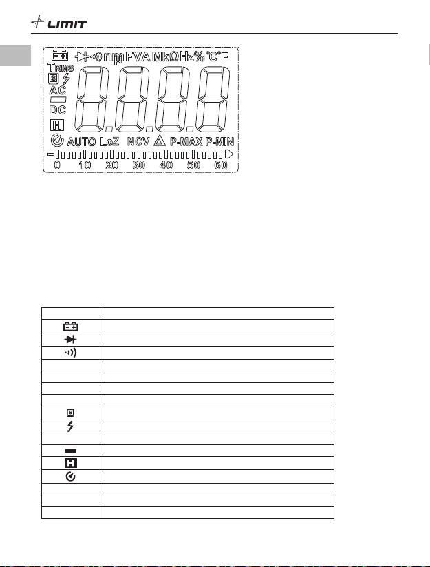
SYMBOLS
Symbol Description
Low battery indication
Diode
Continuity test or continuity beeper tone
Ω, kΩ,MΩResistance units: ohm, kilohm, megohm
Hz, % Frequency, duty ratio
°C/°F Celsius/Fahrenheit
TRMS True RMS
Data transmission
Measured voltage is >30 V (AC or DC)
AC/DC AC/DC measurement
Negative reading
Data hold
Auto power off
AUTO Auto range
LoZ Low impedance measurement
NCV Non-contact voltage detection
GB
5
Relative value measurement
P-MAX / P-MIN Peak measurement
mV, V Voltage units: millivolt, volt
HA, mA, A Current units: microampere, milliampere, ampere
nF, μF, mF Capacitance units: nanofarad, microfarad, millifarad
MAX/MIN Maximum/Minimum measurement
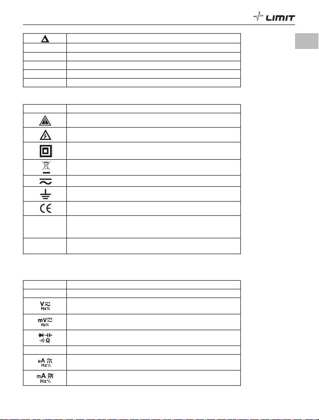
Electrical symbols
Symbol Description
Warning. Risk of Danger. Important information. See manual.
High voltage warning.
DOUBLE INSULATION or REINFORCED INSULATION.
Do not discard this electrical/electronic product in domestic
household waste.
Both direct and alternating current.
Earth (ground) Terminal.
Conforms to European Union directives.
CAT III It is applicable to testing and measuring circuits connected
to the distribution side of the building’s low-voltage MAINS
installation.
CAT IV It is applicable to testing and measuring circuits connected to
the source of the building’s low-voltage MAINS installation.
FUNCTION DIAL AND FUNCTION BUTTONS
1. Function Dial
Dial Position Description
OFF Power off
AC/DC voltage measurement/Frequency and duty ratio
measurement
AC/DC millivolt voltage measurement/Frequency and duty ratio
measurement
Diode test/Continuity test/Resistance measurement/
Capacitance measurement
Hz% Frequency and duty ratio measurement
AC/DC microampere current measurement/Frequency and duty
ratio measurement
AC/DC milliampere current measurement/Frequency and duty
ratio measurement
GB

6
AC/DC ampere current measurement/Frequency and duty ratio
measurement
NCV Non-contact voltage detection
LozV Low impedance measurement
2. Function Buttons
Short press: Press a button for less than 2 seconds.
Long press: Press a button for more than 2 seconds.
2.1 Button
Short press to switch between functions in each multi-function position.
2.2 Button
Short press to enter the manual range mode and change the range. Long press to enter auto mode.
2.3 USB Button
Short press to switch between frequency and duty ratio measurement.
Long press to turn on/off data communication (note: only available when USB communication module
is inserted into the meter casing).
2.4 Button
Short press to enter/exit the relative value measurement mode.
2.5 PEAK
MAX MIN Button
Short press to cycle through the measured maximum and minimum.
Long press to cycle through the peak maximum and peak minimum.
2.6 Button
Short press to hold the measurement on the display. The symbol “ ” will be displayed.
Short press again to cancel data hold.
Long press to turn on/off the backlight.
OPERATING INSTRUCTIONS
• To avoid false reading, replace the battery if the battery low power symbol appears (when the
battery voltage is ≤4.6 V ± 0.2 V). Also pay special attention to the warning sign next to the test
lead jack, indicating that the tested voltage or current must not exceed the values listed on the meter.
• The meter automatically shuts down if there is no operation for 15 minutes. You can wake up the
meter by pressing this button. To disable auto shutdown, press and hold the button in
the off state, and then turn on the meter. Restart the meter to restore auto function.
• Buzzer alarm during measurement: When the input voltage >1000 V or current >10 A, the buzzer
will sound an alarm.
GB

7
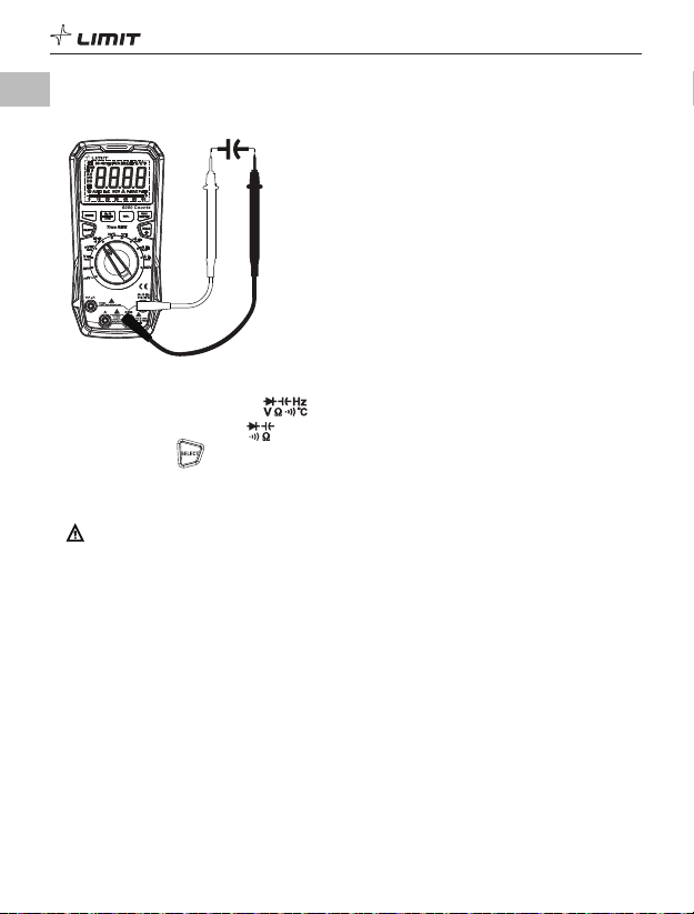
1. AC voltage measurement (P 3)
DM 620
USB
P 3
1.1 Insert the red test lead into the jack, and the black test lead into the COM jack.
1.2 Turn the function dial to the position.
1.3 Short-press the button to switch to AC voltage measurement.
1.4 Connect the test leads in parallel with the measured load or power supply.
1.5 Read the voltage value on the display (if the voltage is >1000 V, the red indicator light will be lit
and the buzzer will sound an alarm).
1.6 Short-press the USB button to display the frequency/duty ratio of the measured voltage.
Caution:
• Do not input a voltage over 1000 V or it may damage the meter.
• Take care to avoid electric shock when measuring high voltages.
• After completing the measurement, disconnect the test leads from the circuit under test.
• Before each use, verify meter operation by measuring a known voltage.
• The input impedance of the meter is about 10 MΩ. The effect of this load may cause measurement
errors in high-impedance circuits. In most cases, if the impedance of the circuit is below 10 kΩ, the
error can be ignored (≤0.1%).
2. DC voltage measurement (P 4)
DM 620
USB
P 4
GB

8
2.1 Insert the red test lead into the jack, and the black test lead into the COM jack.
2.2 Turn the function dial to the position.
2.3 Short-press the button to switch to DC voltage measurement if required.
2.4 Connect the test leads to the measured load or power supply in parallel.
2.5 Read the voltage value on the display (if the voltage is >1000 V, the red indicator light will be on
and the buzzer will sound an alarm).
3. AC/DC millivolt voltage measurement (P 5)
DM 620
USB
P 5
3.1 Insert the red test lead into the jack, and the black test lead into the COM jack.
3.2 Turn the function dial to the position.
3.3 Short press the button to switch to AC/DC millivolt voltage measurement if required.
3.4 Connect the test leads in parallel with the measured load or power supply.
3.5 Read the voltage value on the display.
3.6 When measuring AC millivolt voltage, short-press the USB button to display the frequency/duty
ratio of the measured voltage.
Caution:
• Do not input a voltage over 1000 V or it may damage the meter.
• Take care to avoid electric shock when measuring high voltages.
• After completing the measurement, disconnect the test leads from the circuit under test.
• Before each use, verify meter operation by measuring a known voltage.
• The input impedance of the AC mV range is about 10 MΩ. The effect of this load may cause
measurement errors in high-impedance circuits. In most cases, if the impedance of the circuit is
below 10 kΩ, the error can be ignored (≤0.1%).
• The input impedance of the DC mV range is infinite (about 1 GΩ), and it does not attenuate when
measuring weak signals, so the measurement accuracy is high. When the test leads are open, there
may be a value on the screen, but this is normal and will not affect the measuring result.
• Frequency measurement at 60 mV range (AC voltage) is for reference only.
GB

9
4. LoZ (low impedance) ACV measurement (P 6)
DM 620
USB
P 6
4.1 Insert the red test lead into the jack, and the black test lead into the COM jack.
4.2 Turn the function dial to the LozV position.
4.3 Connect the test leads in parallel with the measured load or power supply.
4.4 Read the voltage value on the display.
4.5 Short-press the USB button to display the frequency/duty ratio of the measured voltage.
Caution:
• Do not input a voltage over 1000 V or it may damage the meter.
• Take care to avoid electric shock when measuring high voltages.
• After completing the measurement, disconnect the test leads from the circuit under test.
• Before each use, verify meter operation by measuring a known voltage.
• After using the LoZ function, wait 3 minutes before next operation.
• LoZ ACV measurement eliminates ghost voltage for more accurate measurement.
5. Resistance measurement (P 7)
DM 620
USB
P 7
GB

10
5.1 Insert the red test lead into the jack, and the black test lead into the COM jack.
5.2 Turn the function dial to the position.
5.3 Touch the probes to the test points in the circuit.
5.4 Read the resistance value on the display.
Caution:
• Take care when working with voltages above AC 30 V RMS, 42 V peak or DC 60 V. Such voltages
pose a shock hazard.
• If the measured resistor is open or the resistance exceeds the maximum range, the LCD will display
“OL”.
• Before measuring resistance, switch off the power supply to the circuit, and fully discharge all
capacitors.
• When measuring low resistance, the test leads will produce 0.1~0.3 Ωmeasurement error. To obtain
an accurate measurement, short-circuit the test leads and use the relative value measurement (REL)
mode.
• If the resistance is not less than 0.5 Ωwhen the test leads are short-circuited, please check if the
test leads are loose or defective.
• When measuring high resistance, it is normal to take a few seconds to stabilize the reading.
6. Continuity test (P 8)
DM 620
USB
P 8
6.1 Insert the red test lead into the jack, and the black test lead into the COM jack.
6.2 Turn the function dial to the position.
6.3 Short-press the button to switch to continuity test.
6.4 Touch the probes to the test points in the circuit.
6.5 Measured resistance <50 Ω: The circuit has good continuity; the buzzer beeps continuously and the
green indicator light is on.
GB

11
Caution:
• Take care when working with voltages above AC 30 V RMS, 42 V peak or DC 60 V. Such voltages
pose a shock hazard.
• Before testing continuity, switch off the power supply to the circuit, and fully discharge all
capacitors.
7. Diode test (P 9)
D
DM 620
USB
P 9
7.1 Insert the red test lead into the jack, and the black test lead into the COM jack.
7.2 Turn the function dial to the position.
7.3 Short-press the button to switch to diode test if required.
7.4 Connect the red probe to the diode anode, and the black probe to the diode cathode.
7.5 Read the forward bias value on the display.
7.6 Measured value <0.12 V: The diode may be damaged; the red indicator light is on.
Measured value within 0.12~2 V: The diode is normal; the green indicator light is on (for reference
only).
7.7 If the diode is open or its polarity is reversed, the LCD will display “OL”. For silicon PN junction, the
normal value is generally about 500~800 mV.
Caution:
• Take care when working with voltages above AC 30 V RMS, 42 V peak or DC 60 V. Such voltages
pose a shock hazard.
• Before testing the diode, switch off the power supply to the circuit, and fully discharge all
capacitors.
GB
12
8. Capacitance measurement (P 10)
C
DM 620
USB
P 10
8.1 Insert the red test lead into the jack and the black test lead into the COM jack.
8.2 Turn the function dial to the position.
8.3 Short-press the button to switch to capacitance measurement.
8.4 Touch the probes to the capacitor pins.
8.5 Read the capacitance value on the display after it stabilizes.
Caution:
• Take care when working with voltages above AC 30 V RMS, 42 V peak or DC 60 V. Such voltages
pose a shock hazard.
• Before measuring, fully discharge all capacitors (especially high-voltage capacitors) to avoid
damage to the meter and user.
• If the measured capacitor is short-circuited or the capacitance exceeds the maximum range, the
LCD will display “OL”.
• When measuring high capacitance, it is normal to take a few seconds to stabilize the reading.
• For small capacitance measurements, it is recommended that REL mode is used to avoid the
influence of distributed capacitance and to obtain a correct reading.
GB

13
9. Frequency/Duty ratio measurement (P 11)
DM 620
USB
P 11
9.1 Insert the red test lead into the terminal, and the black test lead into the COM terminal.
9.2 Turn the function dial to the Hz% position.
9.3 Short-press the USB button to switch to frequency/duty ratio measurement if required.
9.4 Read the frequency/duty ratio value on the display.
Caution:
Take care when working with voltages above AC 30 V RMS, 42 V peak or DC 60 V. Such voltages pose a
shock hazard.
10. Temperature measurement (P 12)
DM 620
A
FUSED
1000V max
MAX 10sec
EACH 15min
USB
P 12
10.1 Turn the function dial to the °C°F position, “OL” appears on the display.
10.2 Insert the K-type thermocouple into the adapter socket, then insert the adapter socket into the
input terminals.
10.3 Put the temperature sensing end of the thermocouple close to the object surface under test.
10.4 Read the temperature value on the display after it stabilizes.
GB
14
10.5 Short-press the button to switch between °C and °F.
Caution:
• Only a K-type thermocouple can be used.
• Max. temperature 230°C/446°F (°F = °C × 1.8 + 32)
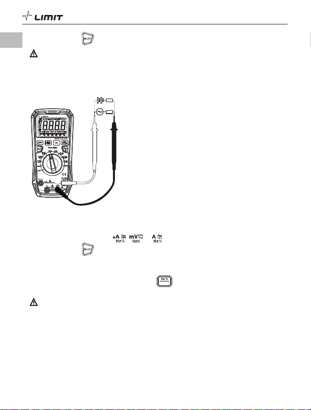
11. AC/DC current measurement (P 13)
RL
RL
A C/DC
DM 620
USB
P 13
11.1 Insert the red test lead into the mA/μAor Aterminal, and the black test lead into the COM
terminal.
11.2 Turn the function dial to the , or position.
11.3 Short-press the button to switch to AC/DC current measurement if required.
11.4 Connect the test leads in series with the measured load or power supply.
11.5 Read the current value on the display (if the current is >10 A, the red indicator light will be on and
the buzzer will sound an alarm).
11.6 When measuring AC current, short-press the USB button to display the frequency/duty ratio of
the measured current.
Caution:
• To prevent possible electric shock, fire, or personal injury, switch off the power supply to the circuit,
then connect the meter in series with the circuit before measuring the current.
• If the range of the measured current is unknown, select the maximum range and then reduce
accordingly.
• There are fuses inside mA/μAand Ainput terminals. Do not connect the test leads in parallel with
any circuit.
• If the measured current is >5 A, each measurement time should be ≤10 s and the rest interval should
be ≥15 minutes.
• If the temperature of the meter rises above 75°C after measurement of a large current, the yellow
indicator light will come on, the buzzer will beep, and the LCD will display “CUT”. When the
temperature drops to <40°C, the yellow indicator light will turn off, and the measurement can be made.
GB

15
12. Non-contact voltage (NCV) detection (P 14)
DM 620
USB
P 14
12.1 Turn the function dial to the NCV position.
12.2 Put the NCV detector (top left corner of the meter) close to the wire (AC) under test.
12.3 If the voltage of the wire is ≥50 V RMS (frequency: 50/60 Hz), the red indicator light will be on
and the buzzer will beep. If no voltage is detected, the LCD will display “EF”. As the intensity of
the detected voltage increases, more segments “-” will be displayed, and the frequency of buzzer
beeping and red indicator light flashing will increase.
Caution:
• The detected voltage level varies with the distance between the NCV detector and the wire under
test.
• The detected voltage level is for reference only, not for specific measurement. The frequency of the
detected voltage should be 50/60 Hz.
• Hold the meter casing for non-contact voltage detection.
13. USB data transmission (P 15a, P 15b)
P 15a P 15b
13.1 Pull out the USB sealing cover at the back of the meter (Picture 15a).
13.2 Insert the USB communication module into the USB access port of the meter and the LCD will
display “ ” (Picture 15b).
13.3 If USB data transmission is not needed during measurement, long-press the USB button or pull
out the USB module to disable data transmission, and “ ” will disappear.
GB
16
13.4 To recover this function, long-press the USB button or insert the USB module.
13.5 The USB communication software can be downloaded from the official website of Limit (www.
limit-tools.com).
ELECTRICAL SPECIFICATIONS
Accuracy: ± (a% of reading + b digits).
Ambient temperature: 23°C ± 5°C (73.4°F ± 9°F) Relative humidity: ≤75%
Caution:
To ensure measurement accuracy, the operating temperature should be within 18°C~28°C and the
fluctuation range should be within ±1°C. When the temperature is <18°C or >28°C, add temperature
coefficient error: 0.1 × (specified accuracy)/°C.
1. DC voltage
Range Resolution Accuracy
60.00 mV 0.01 mV ± (0.8%+5)
600.0 mV 0.1 mV ± (0.8%+3)
6.000 V 0.001 V ± (0.5%+3)
60.00 V 0.01 V ± (0.5%+3)
600.0 V 0.1 V
1000 V 1 V ± (1.0%+3)
• Input impedance: About 1 GΩfor mV range, about l0 MΩfor other ranges
• Accuracy guarantee: 1%~100% of range; short circuit allows least significant digit ≤5
• Max input voltage: 1000 V (if the voltage is >1000V, the red indicator light will be on and the buzzer
will sound an alarm; if the voltage is >1010 V, the LCD will display “OL”)
• Overload protection: 1000 V
2. AC voltage
Range Resolution Accuracy
60.00 mV 0.01 mV ± (1.2%+5)
600.0 mV 0.1 mV ± (1.2%+5)
6.000 V 0.001 V ± (1.0%+3)
60.00 V 0.01 V ± (1.0%+3)
600.0 V 0.1 V ± (1.0%+3)
1000 V 1 V ± (1.2%+5)
LoZ AC V 600.0 V 0.1 V ± (2.0%+5)
• Input impedance: About l0 MΩ
• Display: True RMS
• Frequency response: 40 Hz ~ 1 kHz
• The AC crest factor can be ≤3.0 at 3000 counts, and can only be ≤1.5 at 6000 counts. The additional
error should be added according to the crest factor for a non-sinusoidal wave, as follows:
a. Add 4% when crest factor is 1~2
b. Add 5% when crest factor is 2~2.5
c. Add 7% when crest factor is 2.5~3
GB

17
• Frequency measurement range: 40 Hz~1 kHz, input amplitude: ≥10% of voltage range. Duty ratio is
for reference only
• Accuracy guarantee: 2%~100% of 60 mV range, 1 %~100% of other ranges; short circuit allows least
significant digit ≤3
• Max input voltage: 1000 V (if the voltage is >1000 V the red indicator light will be on and the buzzer
will sound an alarm; if the voltage is >1010 V, the LCD will display “OL”)
• Overload protection: 1000 V
3. Resistance
Range Resolution Accuracy
600.0 Ω0.1 Ω± (1.2%+2)
6.000 kΩ1 Ω
± (1.0%+2)60.00 kΩ10 Ω
600.0 kΩ100 Ω
6.000 MΩ1 kΩ± (1.2%+2)
60.00 MΩ10 kΩ± (2.0%+5)
• Measurement result = displayed value - resistance of shorted test leads
• Open-circuit voltage: About 1 V
• Accuracy guarantee: 1%~100% of range
• Overload protection: 1000 V
4. Continuity and diode
Range Resolution Remarks
0.1 ΩBroken circuit: Resistance ≥70 Ω, no beep. Good continuity:
Resistance <50 Ω, audio/visual alarm.
0.001 V
Open-circuit voltage: About 3V.
For normal diodes, the buzzer will beep once.
For short circuit, the buzzer will beep for a long time.
• Overload protection: 1000 V
• When the forward voltage drop is within 0.12~2 V, the buzzer will beep once.
When the forward voltage drop is <0.12 V, the buzzer will beep for a long time.
5. Capacitance
Range Resolution Accuracy
60.00 nF 10 pF
± (3%+5)
600.0 nF 100 pF
6.000 μF 1 nF
60.00 μF 10 nF
600.0 μF 100 nF
6.000 mF 1 μF± (10%+5)
60.00 mF 10 μF
• Overload protection: 1000 V
• Measurement result = Displayed value - capacitance of open-circuit test leads
GB

18
• For capacitance ≤1 μF, it is recommended to use the REL mode to deduct the open-circuit reading
• Accuracy guarantee: 1~100% of range
• For ranges of 60 mF. the measurement time is about 20 s
6. Temperature
Range Resolution Accuracy
-40~1000°C
-40~0°C
0.1°C~1°C
± (1.0%+30°C)
0~300°C ± (1.0%+20°C)
300~1000°C ± (1.0%+3°C)
-40~1832°F
-40~32°F
0.2°F~2°F
± (1.0%+60°F)
32~572°F ± (1.0%+40°F)
572~1832°F ± (1.0%+6°F)
• The measured temperature should be less than 230°C/446°F
7. DC current
Range Resolution Accuracy
600.0 μA0.1 μA± (1.0%+2)
6000 μA 1 μA
60.00 mA 10 μA± (1.0%+3)
600.0 mA 0.1 mA
6.000 A 1 mA ± (1.2%+5)
20.00 A 10 mA
• Overload protection:
mA/μA range: F1 Fuse 600 mA 1000 V Ф6 × 32 mm.
A range: F2 Fuse 11 A 1000 V Ф10 × 38 mm
• Open circuit allows least significant digit ≤5
• Accuracy guarantee: 1~100% of range
8. AC current
Range Resolution Accuracy
600.0 μA0.1 μA± (1.2%+5)
6000 μA 1 μA
60.00 mA 10 μA± (1.5%+5)
600.0 mA 0.1 mA
6.000 A 1 mA ± (2.0%+5)
20.00 A 10 mA
• Display: True RMS
• Frequency response: 40 Hz ~ 1 kHz
• Accuracy guarantee: 5~100% of 600.0 μA range.
1~100% of other ranges; open circuit allows least significant digit ≤5
• The AC crest factor can be ≤3.0 at 3000 counts, and can only be ≤1.5 at 6000 counts. The additional
error should be added according to the crest factor of a non-sinusoidal wave, as follows:
a. Add 4% when crest factor is 1~2
b. Add 5% when crest factor is 2~2.5
GB
Table of contents
Languages:
Other LIMIT Multimeter manuals


Popular Multimeter manuals by other brands

BGS technic
BGS technic 2202 manual

Steinberg Systems
Steinberg Systems SBS-DM-1000 user manual

PeakTech
PeakTech 3450 Operation manual

Gossen MetraWatt
Gossen MetraWatt METRA HIT 28 S Operation instructions

Testboy
Testboy TB 27 Analog operating manual

National Instruments
National Instruments NI PXI-4060 Getting started guide


