OPERATION
Before taking any measurements, read the Safety
Information Section. Always examine the instrument
for damage, contamination (excessive dirt, grease,
etc.) and defects. Examine the test leads for cracked
or frayed insulation. If any abnormal conditions exist
do not attempt to make any measurements.
Input Warning Beeper
The meter has a beeper that warns the user when
the test lead is in the current socket while the meter
is switched to make a voltage measurement.
Another safety feature to protect the meter and you.
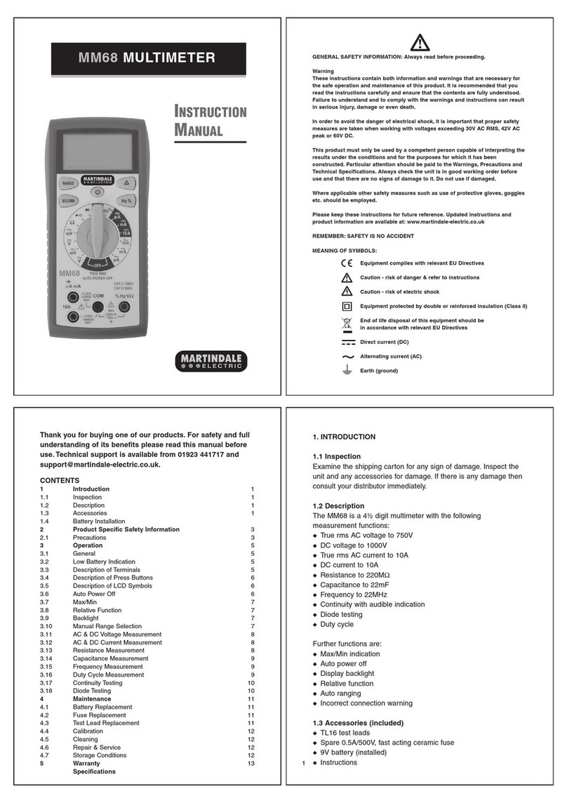
Manually Selecting A Range
The meter also has a manual range mode. In manual
range, you select and lock the meter in a range. To
manually select a range:
Press [RANGE] button to hold the selected range.
Subsequently pressing the [RANGE] button will
select each range in sequence from the lowest to
highest range. Hold the button for 2 seconds to
return to the Autorange Mode.
Mode Switch (DC/AC), /
Press this switch to toggle between DC and AC in
the current measurements. Press this switch to
toggle between thecontinuity/diode modes, if the
function switch is set / to position.
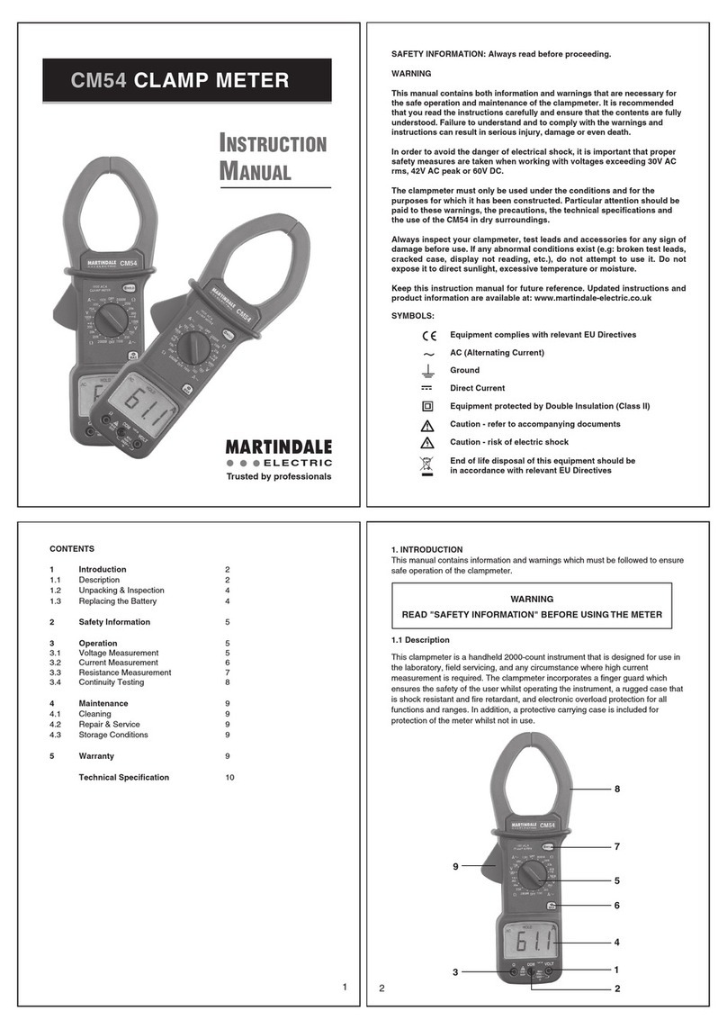
Voltage Measurements
1. Connect the red test lead to the "VΩ" socket and
the black test lead to the "COM" socket.
2. Set the Function switch to the desired voltage type
(DCV) or (ACV) position.
3. Touch the probes to the test points, the range will
change automatically to the level that will display the
input voltage with best resolution.
4. The value indicated in the display window is the
measured value of voltage with proper decimal point
and annunciator indication.
5. For DC, a (-) is displayed for negative polarity;
positive polarity is implied.
Current Measurements
1. Set the Function switch to the desired current
range (µA, mA or 10A) position.
2. To toggle between “DC” and “AC” mode, press
Mode switch. The “DC” or “AC” annunciator is
displayed in the upper left corner.
3. For current measurements less than 320mA,
connect the red test lead to the µA/mA socket and the
black test lead to the COM socket.
4. For current measurements of 320mA or greater,
connect the red test lead to the 10A socket and the
black test lead to the COM socket.
5. Remove power from the circuit under test and
open the normal circuit path where the measurement
is to be taken. Connect the meter IN SERIES with the
circuit.
6. Apply power and read the value from the display.
Resistance Measurements
1. Set the Function switch to the “Ω” position.
2. Turn off power to the circuit under test. External
voltage across the components causes invalid
readings.
3. Connect the red test lead to the “VΩ” socket and
the black test lead to the “COM” socket.
4. Connect the test leads to the point of
measurements and read the value from the display.
Testing Diodes
1. Set the Function switch to / position.
2. Turn off power to the circuit under test. External
voltage across the components causes invalid
readings.
3. To toggle between the continuity/diode modes,
press Mode switch.
4. Touch probes to the diode. A forward-voltage
drop is about 0.6V (typical for a silicon diode).
5. Reverse probes. If the diode is good, “OL” is
displayed. If the diode is shorted, a value near 0mV
will be displayed.
6. If the diode is open, “OL” is displayed in both
directions.
Continuity Measurements
1. Set the Function switch to / to position.
2. Turn off power to the circuit under test. External
voltage across the components causes invalid
readings.
3. To toggle between the continuity/diode modes,
press Mode Switch.
4. Connect the test leads to the two points at which
continuity is to be tested. The buzzer will sound if the
resistance is less than approximately 20Ω.
MAINTENANCE
Battery Replacement
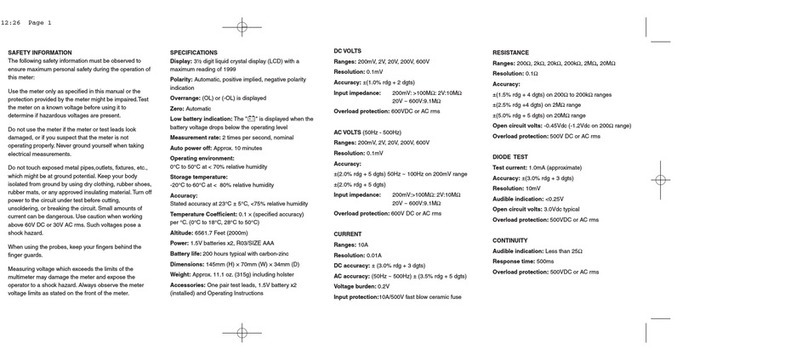
Power is supplied by a 9 volt "transistor" battery.
(NEDA 1604, IEC 6F22, PP3). The appears on
the LCDdisplay when replacement is needed. To
replace the battery, remove the three screws from the
back of the meter and lift off the front case. Remove
the battery from case bottom.
Fuse Replacement
If no current measurements are possible, check for a
blown overload protection fuse. There are two fuses; F1
for the mA socket and F2 for the 10A socket. For access
to fuses, remove the three screws from the back of the
meter and lift off the front case. Replace F1 only with
the original type 0.5A/250V, ceramic, fast acting
fuse. Replace F2 only with the original type
10A/600V ceramic, fast acting fuse. The use of other
fuses may cause damage to the meter, invalidate the
warranty and impair the safety of the user. Domestic
‘Plug Top’ fuses should not be used.
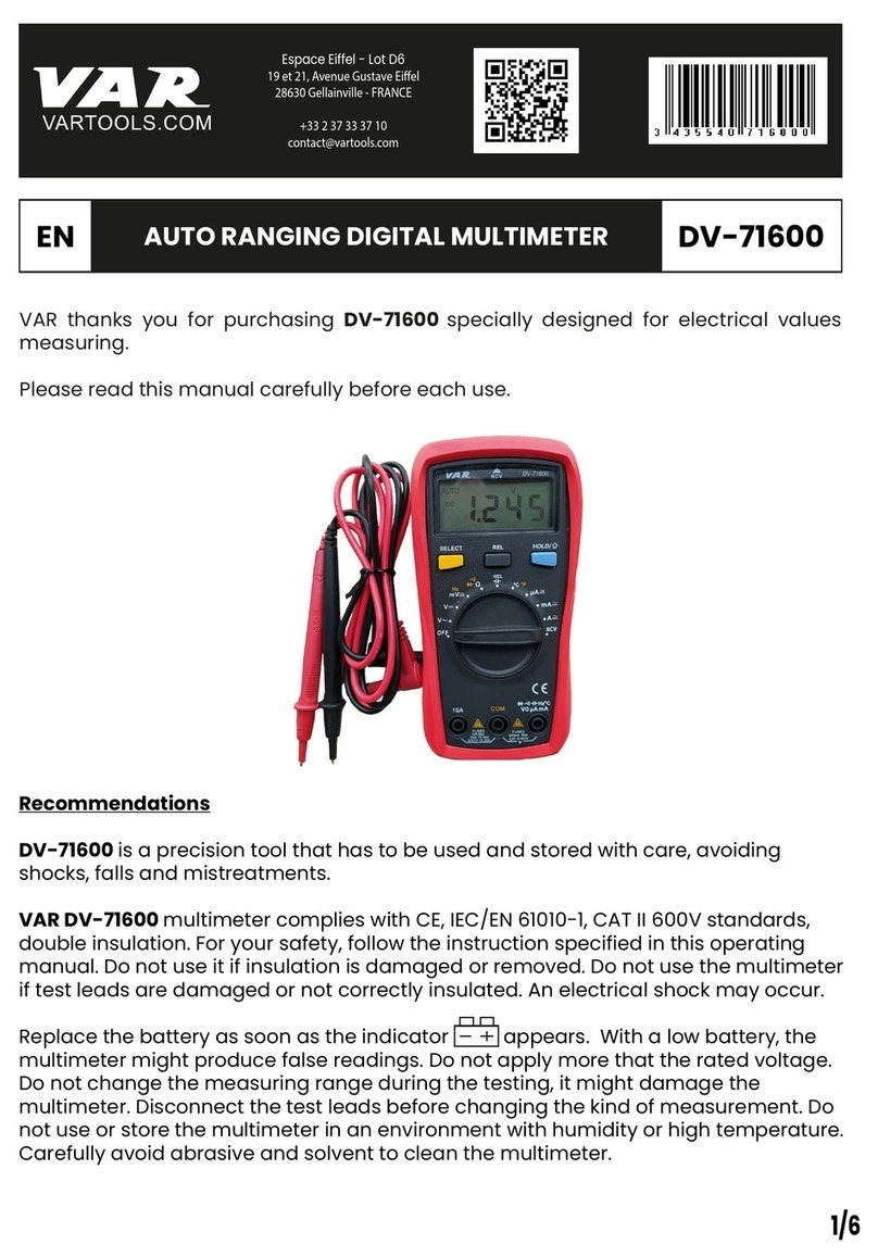
Instrument Repairs and Spare Parts
Apart from the battery and fuses, there are no user
serviceable parts inside. If you suspect that the meter
is not operating properly, please check fuses, battery
and leads.
If the meter is still suspected of being faulty please
contact:
Metrohm House, Penfold Trading Estate,
Imperial Way, Watford, Herts. WD24 4YY, UK.
Tel: 01923 441717 Fax: 01923 446900
Web Site: http://www.martindale-electric.co.uk
WARNING
Remove test leads before changing battery or fuse
Accessories
F1 - 20x5mm 500mA 250V Ceramic -
Ref: FUSE500250 (Pack of 3)
F2 - 1¼ x ¼ ” 10A 600V Ceramic - Ref: FUSE10600
(Pack of 3)
Fused test leads to GS38 specification - Ref: TL55
Soft foam lined carry case - Ref: TC55
MM45 REV3 7/05
