Endorphines GHOST 16hp User manual
FIRMWARE V.1.00 RC

WARRANTY
1-year warranty is guaranteed from the product's purchase date in case of any
manufacturing errors or other functional deficiencies during runtime.
The warranty does not apply in case of:
damage caused by misuse
mechanical damage arising from careless treatment (dropping, vigorous
shaking, mishandling, etc.)
damage caused by liquids or powders penetrating the device
heat damage caused by overexposure to sunlight or heating
electric damage caused by improper connecting
The warranty covers replacement or repair, as decided by us. Please contact us via
email for a return authorization before sending anything. Shipping costs of sending
a module back for servicing is paid by the customer. Device complies with all EU
regulations concerning RoHS lead-free manufacturing and WEEE disposal.
VISIT US:
https://endorphin.es
https://youtube.com/user/TheEndorphines
https://facebook.com/TheEndorphines
https://twitter.com/endorphin_es
https://www.instagram.com/endorphin.es/
https://www.modulargrid.net/e/modules/browser/vendor:167
For technical requests: [email protected]
For dealer / marketing inquiries: [email protected]
ENDORPHIN.ES is a registered trademark. It is doing business as FURTH
BARCELONA, S. L. (EU VAT ID: ES B66836487).

16hp digital audio processing unit without fixed structure:
intuitively create astonishing and ephemeral timbres: from
atmospheric rumbles to heavy or distorted textures
creative stereo effect processor with delay, reverb, filter
and distortion with quickly explorable routing chain with a
single button press
matrix of micro-modulations creates infinite, alive and
unexpected interactions of controls
lush hall and whooshing reverse reverbs with audio freeze
and pre-delay
sidechain audio ducking with trigger input and one knob
single band compressor
new generation ARM Cortex-M7 processor with 96 kHz 32
bit internal processing
zero-delay feedback state-variable filters: bipolar low-pass
/ high-pass, band-pass and alternative comb filter with
resonator
tap delay with external clock and clock divider, 1v/oct time
control for Karplus-Strong, various taps settings with up to 2,5
sec. maximum delay time
8x oversampled distortion algorithm
pre- and post- VCA controls. Tone and Volume controls
with extra gain/drive reserve

INTRO
In collaboration with Andrew Huang, based on his modern music production
techniques we developed a creative audio processor with multiple blocks that can
be moved around in order to achieve different flavors for sound design.
GHOST is a fully digital stereo processing unit without a fixed structure in 16hp:
intuitively create astonishing and ephemeral timbres, from atmospheric rumbles to
heavily distorted textures.
The extremely flexible audio chain consists of a delay, reverb, multimode filter and
distortion, where the order of these audio processing blocks can be easily switched
with a single press of a button.
The ability of the delay to self-oscillate at audio rate frequencies, track 1v/oct
signals, be processed by onboard VCAs and an envelope make GHOST a complete
Karplus-Strong Synthesis voice in itself.
CONNECTING THE POWER
Connect the module directly to the power bus-board with supplied 10-16 ribbon
cable like any other eurorack module. Pair of RED/BROWN pins on the multicolor
ribbon cable corresponds to negative -12V.
TECHNICAL SPECIFICATIONS
Width: 16 hp, depth: 25 cm / 1” with inserted ribbon cable
Current draw: +12V: 130 mA, -12V: 35 mA
Audio I/O: 96kHz 16 bit with 32 bit floating point internal processing
CV capture: 16 bit, 2 kHz
CV range: 0…+5V typically with up to 0…+10V. -5…+5V for 1v/oct and VCF.
Audio input range: typical eurorack standard +/-5V (10Vpp) with up to 18Vpp
when saturation starts (at around +21 dBu). Audio output: typical +/-5V eurorack
standard
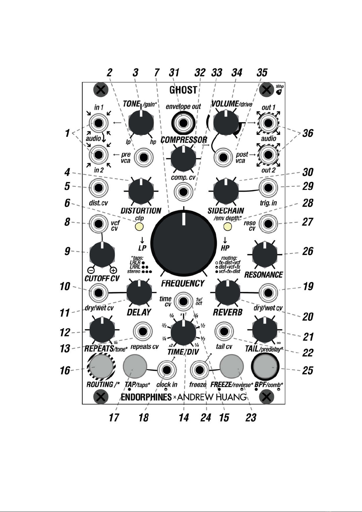
INTERFACE

FRONT PANEL CONTROLS
1.
IN 1, IN 2 JACKS: stereo audio inputs, INPUT 1 (typically left) – is
normalled, i.e. pre-routed
to INPUT 2 (right) when no audio cable is present
on INPUT 2. Typical input audio level: eurorack modular +/-5V with maximum
up to +/-9V when saturation starts with higher audio amplitude.
2.
PRE-VCA CV INPUT JACK: external 0…+5V CV input that controls
the amplitude of the incoming stereo signal. Normalled to +5V when no patch
cable is inserted.
3.
TONE/GAIN* KNOB: multi-function knob. By default it acts as a
6db/oct TILT EQ for low and high frequencies (CCW and CW respectively)
with no effect when the knob is at 12 o’clock. Secondary function is a gain
boost for incoming audio, activated by turning while holding the ROUTING
button. Fully CCW the signal is at its original level - turn CW to boost.
4.
DISTORTION KNOB: manual control over the distortion level. Is
summed with an external CV applied to the DIST. CV jack.
5.
DISTORTION CV JACK: external 0…+5V control over the distortion
level.
6.
CLIP LED: lights up when clipping occurs at the distortion stage.
7.
FREQUENCY KNOB: manual control over the FILTER CUTOFF.
8.
VCF CV INPUT JACK: -5V…+5V CV input for the FILTER CUTOFF.
The polarizer CUTOFF CV knob defines its amount, mixed with the setting of
the FREQUENCY knob.
9.
CUTOFF CV KNOB: polarizer / attenuverter for incoming CV to the
FILTER CUTOFF.
10.
DELAY DRY/WET CV JACK: 0…+5V external CV input for
the DRY/WET mix of the delay effect. Normalled to +5V when no patch cable
inserted.
11.
DELAY KNOB: manual control of the DRY/WET MIX OF THE
DELAY effect, acts as attenuator for DRY/WET CV jack.
12.
REPEATS/TONE* KNOB: manual control over REPEATS or
FEEDBACK level of the delay. Turn it fully CW for self-oscillation. Secondary
/TONE* function (holding ROUTING while turning REPEATS/TONE*) adjusts
the LOW-PASS FILTER after the WET output of the delay chain. Is summed
with an external CV applied to the REPEATS CV jack.
13.
REPEATS CV JACK: 0…+5V external CV input for the
feedback control of the delay effect.

14.
DELAY TIME/DIV KNOB: manual control of the delay speed,
from short audio rate repeats CCW and longer taps CW. When an external
clock is present at the CLOCK IN jack, the knob acts as a divider / multiplier
for this clock with the divisors written around the knob on the panel.
15.
TIME CV INPUT JACK: -5…+5V external CV control for the
speed of the delay’s repetitions, follows 1v/oct tracking. Is summed with the
TIME/DIV knob values when no external CLOCK IN applied. When the delay
is synchronized to external CLOCK IN, that CV sets the clock divider also
summed with the value of TIME/DIV knob.
16.
ROUTING /* BUTTON: routing chain switching as well as
multifunction shift button. Short presses will cycle through three different
orders of audio effects (see FX CHAIN STRUCTURE). Acts as a ‘shift’ button
when held down while using other controls (shift functions are labeled with /*
on the panel).
17.
TAP/TAPS* BUTTON: acts as a tap tempo button for the delay
speed. When internal clock is enabled (no patch cable connected) this button
blinks fully lit, shown by the symbol under it: . When external clock is
patched, the button blinks semi-lit shown by the symbol under it: .
Secondary function (ROUTING + TAPS) changes the stereo behavior of the
taps produced by the delay. Available delay tap configurations are:
LRLR: left and right summed, taps 1 and 3 panned left, taps 2 and 4 panned
right.
LRRL: left and right summed, taps 1 and 4 panned left, taps 2 and 3 panned
right.
STEREO: left and right inputs tap independently in their corresponding left
and right outputs. In this mode the total delay time is halved.
18.
CLOCK IN JACK: 0…+5V external input for the clock that sets
the TEMPO of the delay. External clock sets the delay time in sixteenth
notes. Module switches to external clock automatically when a patch cable is
inserted in the CLOCK IN jack: TAP button blinks semi-lit.
19.
REVERB DRY/WET CV JACK: 0…+5V external CV control
over the DRY/WET MIX OF THE REVERB. Normalled to +5V when no patch
cable is inserted.
20.
REVERB KNOB: manual control of the REVERB DRY/WET mix
level, acts as attenuator for DRY/WET CV jack.
21.
TAIL/PREDELAY* KNOB: primary function controls the decay of
the REVERB’s TAIL, Secondary function in combination with ROUTING /*

button controls the AMOUNT OF PRE-DELAY for the reverb. Is summed with
an external CV applied to the TAIL CV input jack.
22.
TAIL CV INPUT JACK: 0…+5V external CV input for the
DECAY of the reverb.
23.
HOLD/REVERSE* BUTTON: primary function holds or freezes
the reverb, allowing you to ‘hold’ a part of audio until you press this button
again. When hold is enabled, this button is fully lit, shown by the symbol
under it: . Secondary function in combination with ROUTING /* button
switches the algorithm to REVERSE REVERB. When reversed reverb is
activated, the button is semi-lit, shown by the symbol under it:
When REVERSE REVERB is activated, a single HOLD button press along
with FREEZE trigger input activates and deactivates delay freeze
(recirculating delay buffer audio).
24.
FREEZE JACK: 0…+5V external trigger input to enable the
HOLD of the reverb. Has a latch action: each consequent trigger either
enables or disables the freeze.
25.
BPF/COMB* BUTTON: switches the filter type from default
STATE-VARIABLE FILTER LP/HP to BAND-PASS filter and back. When
band-pass filter is enabled, this button is fully lit shown by the symbol under
it: . Secondary function switches to COMB FILTER with resonator by using
the ROUTING + BPF/COMB* button combo. When the COMB FILTER is
activated, the button is semi-lit, shown by the symbol under it: . A second
press on the button switches back to the LP/HP filter (button unlit).
26.
RESONANCE KNOB: manual control over the RESONANCE
OF THE FILTER; is summed with the external CV applied to the
RESONANCE CV input jack. When the BAND-PASS filter is selected, this
knob defines the width of the band. In COMB FILTER mode this knob is
bipolar and defines the feedback adding negative (to CCW) and positive (CW)
combs and at maximum CW/CCW values enables the resonator.
27.
RESONANCE CV INPUT JACK: 0…+5V external CV
control for the RESONANCE of the filter.
28.
/ENV DEPTH* LED: Brightness shows the internally generated
envelope.. When turned while pressing the ROUTING /* button, this LED
shows the amount of the envelope applied to the internal sidechain audio
ducking effect.
29.
TRIGGER INPUT JACK: trigger input for the onboard
sidechain envelope.

30.
SIDECHAIN/ENV DEPTH* KNOB: Sets the decay of the
onboard envelope from zero (no envelope) to approx. 5 seconds. When
turned while pressing the ROUTING /* button, this knob adjusts the depth of
the envelope to the internal sidechain audio ducking effect.
31.
ENVELOPE OUTPUT JACK: 0…+5V envelope output
triggered from TRIG IN jack. The envelope has fixed 1 msec attack and a
natural-sounding exponential curve. While the internal envelope for
sidechaining is negative (to duck the audio) this output provides a positive
version of the envelope to use elsewhere in your system or modulating
module’s parameters.
32.
COMPRESSOR KNOB: manual control over the amount of
compression applied after the effects processing chain, is summed with an
external CV applied to the COMPRESSOR CV IN jack.
33.
COMPRESSOR CV IN JACK: 0…+5V external CV input for
the compressor amount.
34.
VOLUME/DRIVE KNOB: controls the final output volume. Acts
as an attenuator for the POST VCA CV jack. When the knob passes after 15
o’clock it adds extra DRIVE saturation to the output signal while trying to
maintain its amplitude.
35.
POST-VCA CV INPUT JACK: 0…+5V external CV input for
the final volume level. Normalled to +5V when no patch cable is inserted.
36.
OUT 1, OUT 2 JACKS: final stereo audio outputs. OUTPUT 1
is typically left and OUTPUT 2 is typically right. OUTPUTS 1/2 can drive
headphones or be used as separate mono L/R outputs connected with mono
cables. When each jack is used with stereo TRS cables, these outputs can
be used in PSEUDO-BALANCED CONNECTION for example to your audio
interface directly. Pseudo-balanced connection ensures less noise hum on
the long cables but cuts the audio signal amplitude by half – to approximate
pro-line level +/-2.5V. Both audio inputs and outputs support airline audio
jack adapter (sold separately) to connect a 3.5mm TRS stereo (AUX) cable
directly.

TONE SHAPING
TONE knob enables light tone shaping after initial pre-VCA with a light TILT EQ
leaving more low frequencies at knob’s full CCW position, and leaving more high
frequencies at knob’s full CW position. After that stage, the signal is passed to the
main processing chain. By pressing and holding the ROUTING button, TONE/GAIN*
knob acts as a gain booster for the external audio signal from 100% at full CCW to
boosted at full CW.
REMINDER: when digital gain is increased past 100% it brings digital noise, use
at your own discretion.
DISTORTED REALITY
The power of the GHOST lies in its complex stereo audio effect chain with 96kHz,
32-bit internal audio processing, consisting of 2 VCAs (pre and post), 3 distortion
stages, a multimode filter, delay, reverb, compressor, and sidechain ducking
envelope. The order of the three main processing blocks - DELAY/REVERB, VCF,
and DISTORTION - can be changed by pressing the ROUTING button, letting you
achieve many different flavors of sound without having to repatch. The settings of
the GAIN, DRIVE and COMPRESSOR in the audio chain are adjusted manually for
optimal control over the dynamics.
There are three possible orders for the DELAY/REVERB (FX), DISTORTION and VCF
blocks:
FX DISTORTION VCF
DISTORTION VCF FX
VCF FX DISTORTION
The selected order is shown by the brightness of the ROUTING button, and written
as a hint on the faceplate:
when ROUTING button LED is off – first chain is selected
when ROUTING button is semi lit –
second chain is selected
when ROUTING button is fully lit – third chain is selected

HINT: experiment with the audio chain order to fit your needs and find new and
unexpected sounds with a push of a button.
We advise exploring the routing chains and picking your favorite based on each
situation. From our sound design experience with the module, the first routing chain
is well suited to rumble/ghost sounds, the second is good for cleaner effects based
on overdriving the filter, and the third will generally have the heaviest distorted
tones.
THREE FLAVORS OF DISTORTION DIST
/GAIN: digital input gain capable of light saturation, adjusted with ROUTING +
TONE/gain*
DISTORTION: 8x oversampled distortion algorithm
/DRIVE: final output saturator when VOLUME is pushed to the top of its range,
as indicated around the knob on the panel
THREE FLAVORS OF FILTER VCF
Bipolar LP/HP filter
BAND-PASS filter (BPF)
COMB filter with resonator at high resonance settings.
To switch the filter type you simply press the BPF/COMB button. A single press will
switch the filter type to a band-pass, and a combination of ROUTING +
BPF/COMB buttons will change the filter type to Comb, which is also capable of
self-oscillation at full CW or CCW RESONANCE settings. Resonance knob behavior
in Comb filter is special: it is bipolar, so from noon it either adds negative (CCW) or
positive combs (CW).
SPATIAL EFFECTS FX
This chain of audio effects (a.k.a. FX ) consists of a delay which is then routed into
the reverb with mid/side widener.

DELAY: stereo delay with 1v/oct tracking, capable of Karplus-Strong
synthesis. The delay can be synchronized externally via CLOCK IN, or by using the
onboard TAP TEMPO BUTTON, with maximum delay time of 2.5 seconds. 3
configurations of delay taps are available, toggled between by holding the
ROUTING button and short pressing the TAP button. Delay tap configurations are
LRLR, LRRL, and STEREO mode, also known as true stereo, where taps will appear
at OUT 1 or OUT 2 only if something is present at IN 1 or IN 2 respectively.
REVERB: lush stereo hall reverb with additional controls and configurations
such as tail decay adjustment, pre-delay adjustment, reverse reverb and audio
freezing.
MID/SIDE
widener stays after the reverb and increases the stereo field
simultaneously with the amount of TAIL reverb knob. This feature is best audible on
true stereo signals processed with the GHOST.
Both delay and reverb have advanced secondary parameters and modes that can
be accessed by pressing the ROUTING button in combination with either a knob or
another button. These controls are internal and do not have CV control; they are
designed as ‘set and forget’ controls to fine-tune your sound.
ADVANCED DELAY PARAMETERS
ROUTING + REPEATS KNOB: controls the light TILT EQ that
adjusts the TONE / brightness of repetitions: from sparkling clean to dub delays.
That TONE* range for repeats is identical to TONE input shaping control.
ROUTING + TAP BUTTON: switches the way the delay taps are
distributed (hard panned) in the stereo OUTPUTS 1/2. When the TAP button blinks
once – the taps appear on OUTPUTS 1 and 2 in an LRLR pattern. When the TAP
button blinks twice – the tap pattern is LRRL. When the TAP button blinks 3
times – STEREO mode is selected, where the delay taps appear on
either L or R output only when there is something present on L or R input, aka true
stereo operation. The true stereo mode shortens the maximum delay time by half.
NOTE: Tap tempo via the TAP button doesn’t work if an external clock is
applied.

ADVANCED REVERB PARAMETERS
ROUTING + TAIL KNOB: sets the PRE-DELAY amount for the reverb,
which is an important control that can add additional depth to your sounds,
particularly useful when processing percussion. Full CCW knob position
corresponds to no pre-delay and full CW position corresponds to maximum
possible pre-delay time (up to 0.5 seconds). The pre-delay setting is especially
useful when used with REVERSE reverb.
HOLD BUTTON: freezes the reverb creating an infinite recirculation in the
feedback loop, which is reminiscent of what is called a ‘wall of sound’. When
REVERSE REVERB is activated (see next), HOLD button activates and deactivates
freeze for the delay (recirculating delay buffer audio).
ROUTING + HOLD BUTTON: switches the reverb to the REVERSE
algorithm, particularly useful for obtaining whooshing sounds by processing kicks,
snares, pads, vocals and so on, giving you an extra dimension of movement.
DYNAMICS SHAPING
In order to tame our signal at the end of the main processing chain we have the
following dynamics blocks: COMPRESSOR and SIDECHAIN ducking envelope.
COMPRESSOR
One-band peak stereo compressor controlled by a single knob, from none to light
to heavy compression settings with pre-defined and manually tuned values to fit
various music styles for best performance. Compressor behavior varies on the
audio material and music taste. We recommend setting for 12 o’clock for
ambient/pads and full clockwise setting for obtaining snappy drums.
SIDECHAIN DUCKING
Sidechain ducking ‘compression’: this is the last stage in the audio chain before the
final post-VCA volume control. The sidechain envelope is triggered using the
SIDECHAIN TRIG. INPUT jack, its release time is set with the SIDECHAIN knob,
and its depth of ducking is controlled by holding the ROUTING button while turning
the SIDECHAIN knob.

RESET
In case you’ve tweaked everything so hard you’ve distorted signal main outputs,
there is a soft reset that adjusts all advanced / secondary parameters to their
default values, so you may start tweaking from the beginning.
Press all four buttons simultaneously and hold them for more than 3 seconds.
PATCH EXAMPLES
KARPLUS-STRONG SYNTHESIS ROUTING 1
Ghost can function as a complete Karplus-Strong Voice by using the delay at the
shortest time setting for sound generation and built-in filter, VCAs and envelope as
tonal / dynamics control.
Set the ROUTING mode to the first order (FX
DISTORTION
VCF) when
ROUTING button LED is off
Set REPEATS to maximum with TIME/DIV delay time turned fully CCW.
Moderately adjust DELAY DRY/WET to the 12 o’clock
Feed any audio to the GHOST audio inputs to start up the Karplus-Strong
sound generation. You will hear a strong recirculating oscillator sound. Its amplitude
is rather high therefore it is convenient to adjust it by DELAY DRY/WET knob
Patch a trigger / gate signal from your sequencer to the SIDECHAIN TRIGGER
input: this will trigger an internal envelope that will come out from the ENVELOPE
OUT. The decay of the envelope is controlled by the SIDECHAIN knob
Patch the signal from the ENVELOPE OUT to either: DELAY DRY/WET CV IN
or the POST-VCA input to shape our oscillator in different stages
Split the ENVELOPE OUT signal and patch it to the VCF CV input for additional
tonal shaping
Connect the 1v/oct PITCH CV output from your sequencer and patch it to the
TIME CV 1V/OCT input of the DELAY
TIP: if you would like to add one extra octave to the available PITCH range of
the delay, set the TAPS DISTRIBUTION to STEREO mode via ROUTING + TAP.

LOW-END GROOVE A.K.A. TECHNO RUMBLE
BASS ROUTING 2
Moderntechnomusicisdefinedbyagroovylowendrumblewhichalongwiththekick
drumdefinesthekeyelementofthestyle.Ghostcangeneratesuchrumblefromany
transientsoundorsamekickappliedintotheaudioinputs.
•SettheROUTINGmodetothesecondorder(DISTORTION•VCF•FX)whenROUTING
buttonissemilit
•Splityour909stylekickdrumandapplyitintoAUDIOIN1.
•SettheDISTORTIONandCOMPRESSORknobstoowntaste,usuallyaround12
o’clock
•SettheVCFfiltertypetonormalLP/HPandsetthefilterFREQUENCYknobaround11
o’clock
•ApplyclockfromyoursequencerintoCLOCKINjack(typicallyexpectedin16
th
notes)
andsettheTIME/DIVknobtoobtaindesiredrepeats.SetDELAYDRY/WETand
REPEATStoowntaste,usuallybotharound12o’clock
•EnableREVERSEDREVERBbyROUTING+HOLD/reverse*.SetREVERBDRY/WET
andTAILtoyourowntasteuntilyouobtainawhooshingsound.Forpropergroovesetthe
predelayamountbyROUTING+TAIL/preleday*toapprox.12o’clock
•ApplykickdrumtriggerintoSIDECHAINTRIGINjack.Settheduckingenvelope
amountto50%withROUTING+SIDECHAINto12o’clock.ThenmoveSIDECHAINknob
alonetoaround1011o’clocktocatchtheproperpumpingtime
•MixthesoundfromAUDIOOUT1/2withtheoriginalkickdrumusingamixersuchas
Cockpit2.
•TIP:itisbesttokeepyourlowendconsistentorevenbetterMONO.Sowhenusing
thedelaytocreatetherumble,setTAPSDISTRIBUTIONtoSTEREOmodeviaROUTING
+TAPtoavoidPINGPONGeffectorsimplyonlyuseAUDIOOUT1.
GHOST DRONE ROUTING 3
GHOSTstructureandmultidimensionalmodulationmatrixiscapableofproducingdark
dronesandephemeralsoundscapesfulloftextureandharmony.
•SettheROUTINGmodetothethirdorder(VCF•FX•DISTORTION)whenROUTING
buttonLEDisoffwhenROUTINGbuttonisfullylit
.
•SelecttheCOMBFILTERbypressingtheROUTING+FILTERBUTTONandsetthe
RESONANCEfullyCW

•PatchavariablewaveformoscillatorintotheAUDIOIN1,SAWandSQUAREwaves
workbest.FeedanadditionalenvelopeorLFOtothepreVCAinputontheGHOSTto
createmovement.PatchtheAUDIOOUT1/2toyourmixer
•SetDELAYDRY/WETto80%withREPEATSaround3040%,adjustthe
REPEATS/tone*bypressingtheROUTING+REPEATSknobtoaround13:0014:00.
SyncthedelaybysendingaclockfromyoursequencerintotheCLOCKINandleave
TIME/DIVknobat12:00
•SetREVERBDRY/WETto60%withamoderateTAILamountataround40%.Adjust
thePREDELAYbypressingtheROUTING+turningtheTAIL/predelay*knobto
approximately7080%
•SetDISTORTIONto20%andCOMPRESSORto70%tobringinsomenoise
•SendaPITCHsequencetotheVCFCVinput.COMBdoesnottrack1v/oct,butthis
allowsyoutohighlightfrequencieswithoutdoublingtheamplitudeofthefundamentalof
thesoundsource.SettheFREQUENCYCUTOFFknobto11:00withVCFCVattenuverter
fullyCW
•StartthesequencerandlistenhowGHOSTcreatestimbresontopofasteadyoscillator
•Patchanother1v/octPITCHCVsignaltoyouroscillatorandplayaroundwiththenotes,
youwillhearhownewghostharmoniesappear,letthemdirectyournextnote.
FIRMWARE UPDATE
Firmware updates are essential for any digital modules. They bring new features or
bug fixes.
Feel free to write any bugs, features ideas or improvements to [email protected]
To update the firmware on your Ghost, first download the latest firmware file once
available on Endorphin.es website: https://www.endorphin.es/modules/p/ghost
The update procedure is done via audio: either computer or phone will work, we
advise you to disable all notifications (flight mode) so that the update is not
interrupted.
1. Power OFF your modular system.
2. Unplug all the cables from GHOST except a simple mono or stereo cable
connecting the audio output from your computer headphones output to the
‘AUDIO IN 1’ input of the module.
3. Set the output volume of your computer to 100% or slightly lower.
4. Hold ROUTING while powering your system ON - you will see both CLIP and
/ENV DEPTH LEDs on.

5. Open the Ghost_Update_xxx.wav file with any audio player. Press play and
wait 1,5+ minutes while the firmware is updating. Both CLIP and /ENV
DEPTH LEDs will slowly blink during that procedure and a row of 4 buttons
will show the approximate signal level as VU meter.
6. If all 4 buttons LEDs blink fast during update or both CLIP and /ENV DEPTH*
LEDs stop blinking, that means an error occurred in the update and you have
to stop the audio file playback, reset the firmware listening input (single
ROUTING button press), adjust the audio file playback volume and then start
it again.
7. The module will reboot automatically after new firmware is installed.
8. Enjoy the new features.
IMPORTANT: to prevent the errors during the audio playback of the firmware,
please use any audio editor without any effects applied (EQ etc).
CREDITS
ENDORPHIN.ES
x ANDREW HUANG – GHOST
FIRMWARE VERSION 1.00
COLLECTION SPRING/SUMMER 2023
Module idea and concept by Andreas Zhukovsky and Andrew Huang
Hardware design, direction and manual by Andreas Zhukovsky
Core engine programming by BSVi
Firmware polishing, curves, additional features by Kouik03
Manual proofreading and beta-testing: Wisdom Water
ENDORPHIN.ES are made in Barcelona, Spain
Follow, like, post and tag us at Instagram: @endorphin.es
Table of contents
Other Endorphines Recording Equipment manuals


Popular Recording Equipment manuals by other brands


HiFi Engine
HiFi Engine BR-20 series Maintenance manual

Hameg
Hameg HM8037 manual

Glensound
Glensound DARK8ADI Product details

Northern Airborne Technology
Northern Airborne Technology AA224 series Installation and operation manual

Denon
Denon DN-F450R owner's manual

TC Electronic
TC Electronic DVR250-DT user manual