WirelessHART Adapter SWA70 Table of Contents
Endress+Hauser 3
Table of Contents
Revision history . . . . . . . . . . . . . . . . . . . . . . 5
Registered trademarks . . . . . . . . . . . . . . . . . 6
1 Safety instructions . . . . . . . . . . . . . . . . 7
1.1 Designated use . . . . . . . . . . . . . . . . . . . . . . . . . . . . 7
1.2 Installation, commissioning and operation . . . . . . . . 7
1.3 Operational safety . . . . . . . . . . . . . . . . . . . . . . . . . . 7
1.4 Declaration of Conformity . . . . . . . . . . . . . . . . . . . . 8
1.5 Radio approvals . . . . . . . . . . . . . . . . . . . . . . . . . . . . 9
1.6 Technical improvement . . . . . . . . . . . . . . . . . . . . . . 9
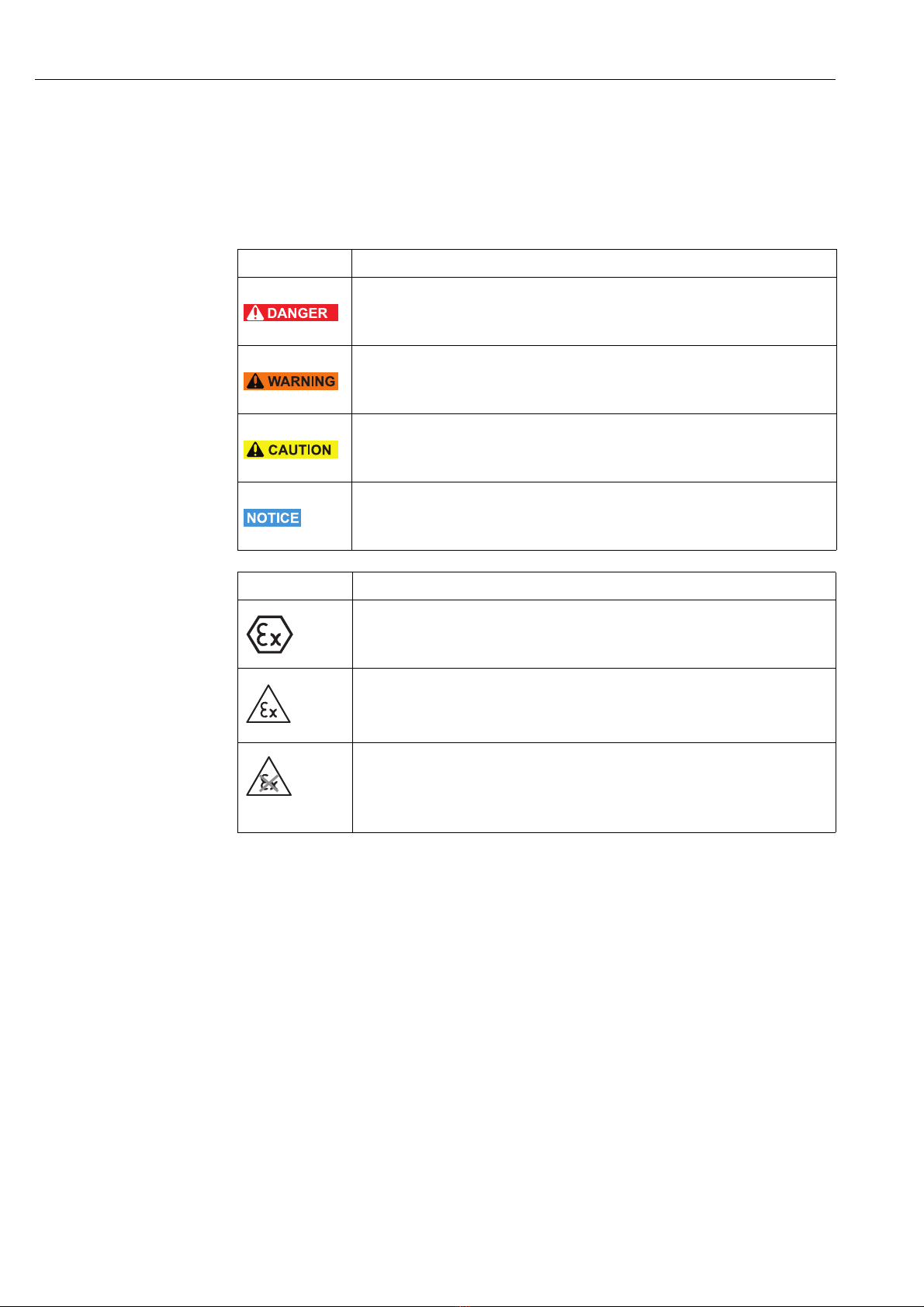
1.7 Conventions used in this manual . . . . . . . . . . . . . . 10
2 Identification . . . . . . . . . . . . . . . . . . . 12
2.1 Unpacking the product . . . . . . . . . . . . . . . . . . . . . 12
2.1.1 Visual inspection . . . . . . . . . . . . . . . . . . . . 12
2.1.2 Scope of delivery . . . . . . . . . . . . . . . . . . . . 12
2.1.3 Storage and transportation . . . . . . . . . . . . . 13
2.2 Nameplate . . . . . . . . . . . . . . . . . . . . . . . . . . . . . . 13
2.3 Ordering information . . . . . . . . . . . . . . . . . . . . . . . 14
2.4 Additional radio approvals . . . . . . . . . . . . . . . . . . . 15
2.5 System requirements . . . . . . . . . . . . . . . . . . . . . . . 15
2.6 Licensing agreement . . . . . . . . . . . . . . . . . . . . . . . 15
3 Function and system design . . . . . . . 16
4 Installation . . . . . . . . . . . . . . . . . . . . 18
4.1 Overview . . . . . . . . . . . . . . . . . . . . . . . . . . . . . . . 18
4.2 Installation conditions . . . . . . . . . . . . . . . . . . . . . . 18
4.3 Design . . . . . . . . . . . . . . . . . . . . . . . . . . . . . . . . . 19
4.4 Mounting on the field device . . . . . . . . . . . . . . . . . 20
4.5 Remote mounting . . . . . . . . . . . . . . . . . . . . . . . . . 21
4.5.1 Wall mounting . . . . . . . . . . . . . . . . . . . . . 22
4.5.2 Pipe mounting . . . . . . . . . . . . . . . . . . . . . . 23
4.6 Post-installation check . . . . . . . . . . . . . . . . . . . . . . 24
5 Electrical installation . . . . . . . . . . . . . 25
5.1 Connecting the WirelessHART Adapter to the
power supply . . . . . . . . . . . . . . . . . . . . . . . . . . . . . 25
5.1.1 Power supply via wide range power unit . . 25
5.1.2 Power supply via solar module connection . 27
5.1.3 Power supply via intrinsically safe
power unit . . . . . . . . . . . . . . . . . . . . . . . . 28
5.1.4 Power supply via battery unit . . . . . . . . . . . 29
5.1.5 Cable specification . . . . . . . . . . . . . . . . . . . 29
5.1.6 Connecting the M12 socket . . . . . . . . . . . . 29
5.2 Connecting the field device . . . . . . . . . . . . . . . . . . 30
5.2.1 Cable specification . . . . . . . . . . . . . . . . . . . 30
5.2.2 Wiring for power supply via electronically
controlled power supply unit . . . . . . . . . . . 31
5.2.3 Wiring for power supply via battery unit . . . 32
5.2.4 Connection data at terminals . . . . . . . . . . . 33
5.2.5 Assignment of the terminals . . . . . . . . . . . . 33
5.3 Wiring diagrams for wide range power unit . . . . . . 34
5.3.1 Field device in a closed-control loop
without a communication resistor . . . . . . . 34
5.3.2 Field device in a closed-control loop
with a communication resistor . . . . . . . . . . 35
5.3.3 Two-wire field device with power supplied
by internal power supply system . . . . . . . . 36
5.3.4 Four-wire field device . . . . . . . . . . . . . . . . 36
5.3.5 Field devices in multidrop . . . . . . . . . . . . . 37
5.4 Wiring diagrams for solar module connection . . . . . 38
5.4.1 Field device in a closed-control loop
without a communication resistor . . . . . . . 38
5.4.2 Field device in a closed-control loop
with a communication resistor . . . . . . . . . . 39
5.4.3 Two-wire field device with power supplied
by adapter . . . . . . . . . . . . . . . . . . . . . . . . . 40
5.4.4 Four-wire field device . . . . . . . . . . . . . . . . 40
5.5 Wiring diagrams for intrinsically safe power unit . . . 41
5.5.1 Field device in a closed-control loop
without a communication resistor or
two-wire field device . . . . . . . . . . . . . . . . . 41
5.5.2 Field device in a closed-control loop
with a communication resistor . . . . . . . . . . 42
5.5.3 Four-wire field device . . . . . . . . . . . . . . . . 43
5.6 Wiring diagrams for battery unit . . . . . . . . . . . . . . . 44
5.6.1 Field device in a closed-control loop
without a communication resistor . . . . . . . 44
5.6.2 Field device in a closed-control loop
with a communication resistor . . . . . . . . . . 46
5.6.3 Two-wire field device with power supplied
by the adapter . . . . . . . . . . . . . . . . . . . . . . 47
5.6.4 Four-wire field device . . . . . . . . . . . . . . . . 48
5.7 Post-connection check . . . . . . . . . . . . . . . . . . . . . . 48
6 Operation . . . . . . . . . . . . . . . . . . . . . 49
6.1 Display and operating elements – main PCB . . . . . . 49
6.1.1 Push button . . . . . . . . . . . . . . . . . . . . . . . . 50
6.1.2 Display . . . . . . . . . . . . . . . . . . . . . . . . . . . 50
6.2 Operating and display elements –
electronically controlled power supply units . . . . . . 51
6.2.1 Push button . . . . . . . . . . . . . . . . . . . . . . . . 51
6.2.2 Light emitting diodes . . . . . . . . . . . . . . . . . 52
6.3 Operating the field device . . . . . . . . . . . . . . . . . . . 52
6.4 Local configuration and remote configuration . . . . . 52